The PCB for this project is for an AM radio circuit but there’s something a bit different about it Is based on vacuum tubes. A few weeks ago, I’ve worked with some vacuum tubes for a pre-amplifier circuit, and I really liked the results. I’ve searched for some more vacuum tubes interesting circuits and I found a radio one. So today I’ll try to explain you how this circuit should work, the parts of such a radio circuit, we assemble my PCB and test it out and listen to some AM radio channels. You should learn something new and interesting so if you want to see if this works, stick till the end. I’m sharing my circuit and the PCB I’ve made on this post, in case you want to try the same project. So, let’s get started.
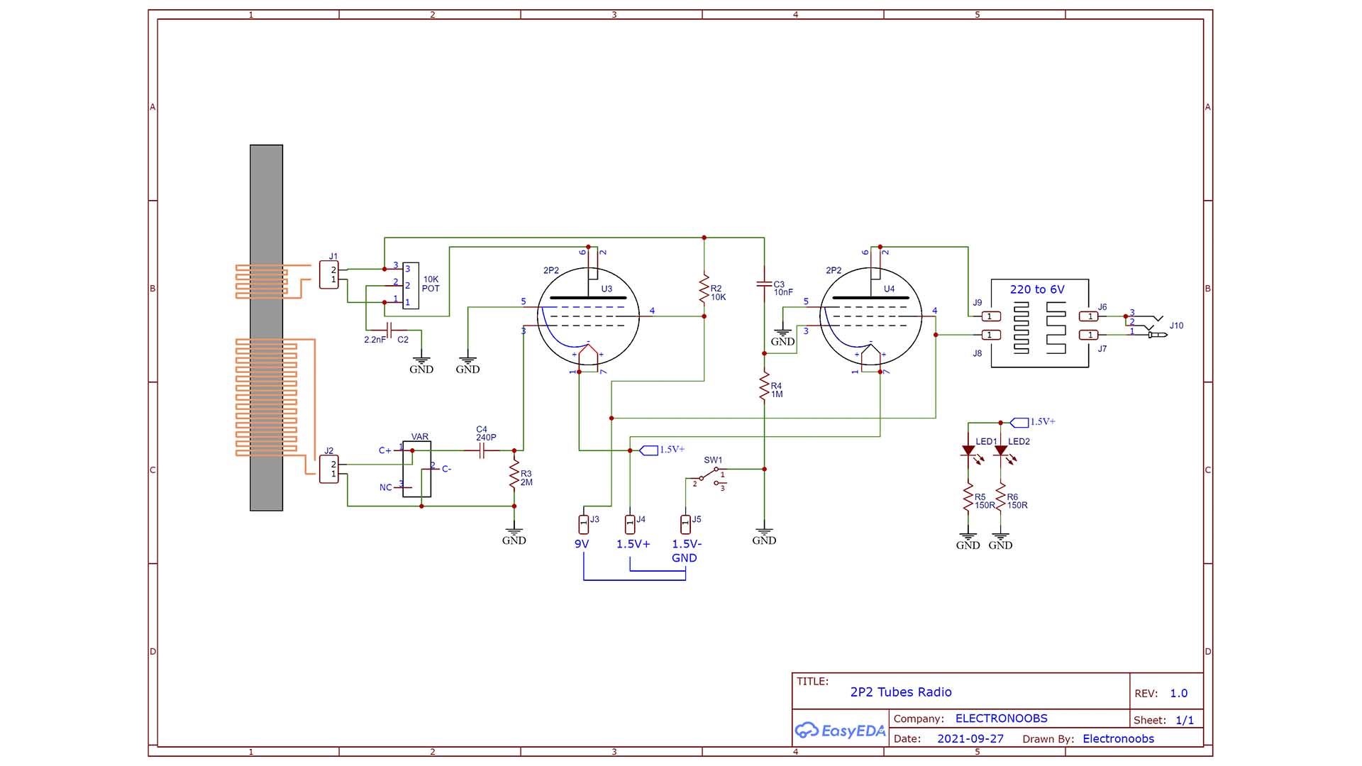
I’ve searched online for a few schematics for a vacuum tube radio and found this one you can see below. The quality was very bad so I’ve made my own schematic using a PCB designing software and this is my final schematic. Once I had this schematics, which we will look over in a few minutes, I’ve passed the circuit to PCB. If you want the same design, download the GERBER files from below a chapter below.
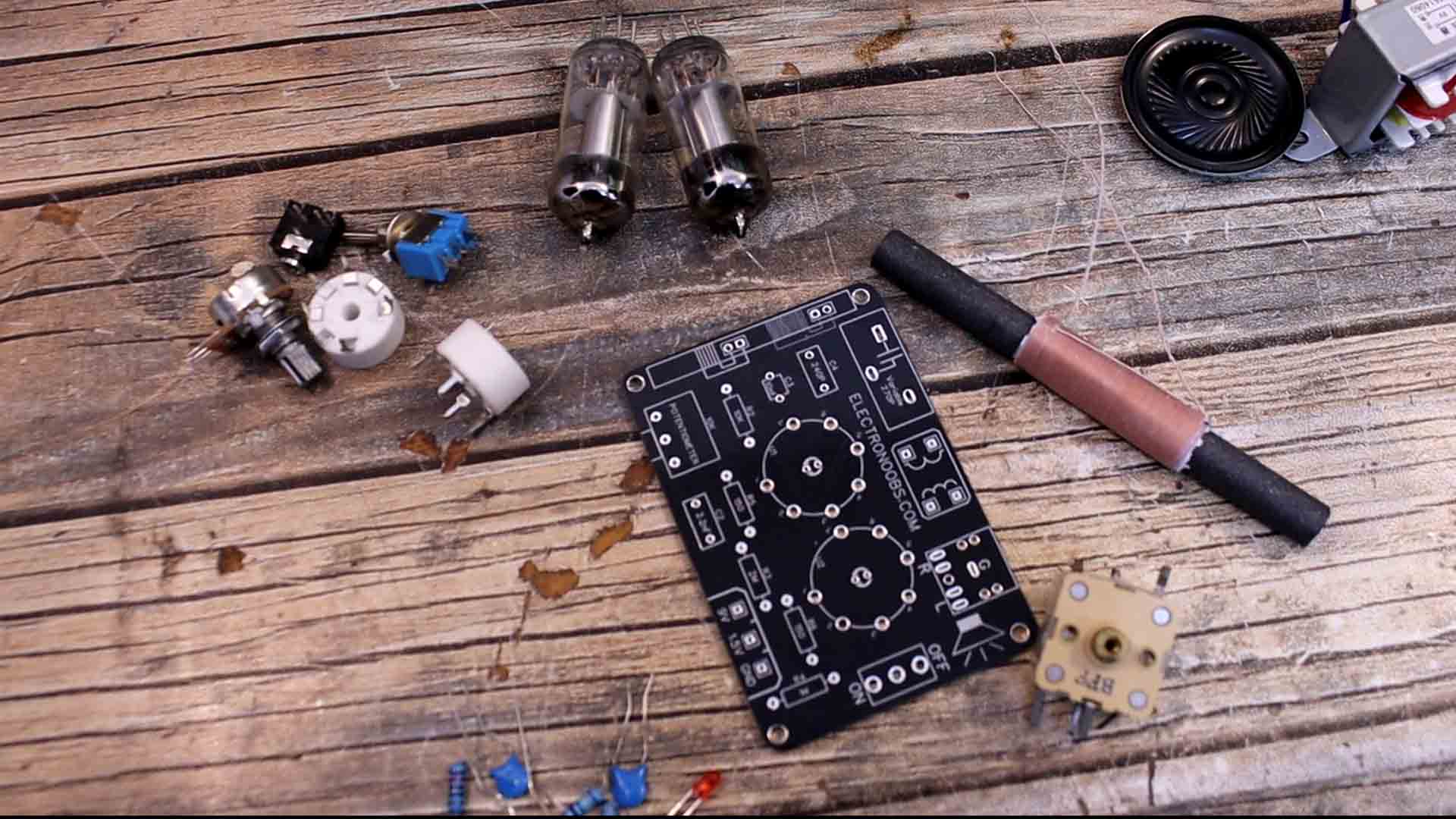
On the next chapter you cn download the PCB GERBER files and order it. Once you receive your boards, get together all the needed components. For the variable capacitor I bought a generic one but I’m not sure which pins I should use. It has 9 pins but we only need 2. We need to find two pins with a capacitance around 270pF. Using my multimeter, I test the pairs of pins and I found 2 with a capacitance of 300pF. For the regenerative coil I bought a typical one. We’ve seen this type of coil on the teardown of the old black and white TV which also had a radio integrated. This is just a ferrite core cylinder with some copper coils on it. One big coil and a smaller one. To find which is which, just use the multimeter in resistance mode and the small coil should have a lower resistance. The rest are just passive components such as resistors, capacitors, a switch and potentiometers. We also need this jack connector for the audio output. And for amplification we need a small transformer with a ratio for 220V to 6V. For the tubes is better to use sockets than soldering them directly to the PCB. So we need two of these sockets and of course the tubes, which are 2P2. For supply we could use a 1.5 and a 9V batteries. But to be sure, I might use my power supply for the tests. That’s all we need, let’s assemble it.
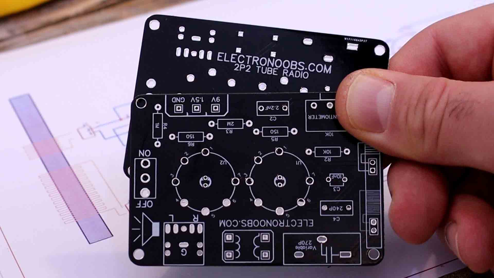
I’ve passed the circuit to PCB and this below is my final board. If you want the same design, download the GERBER files from below and go to PCBWAY.com for example, and click the quote now button and then select your settings. I’ve selected the black color. This is my PCB for this project and PCBWAY did an awesome job. It looks quite nice and it has spaces for two vacuum tubes, some coils, a switch, transformer and all the needed components. I’ve also placed some LEDs below the tubes in case you want to give some color to this project. You have the values I’ve used on the silk-layer but I might change them till the end of the video so check the final schematic. This project is very new to me so I might encounter some problems.
First, I add all the passive components, the resistors, capacitors and all that. Then I add some red LEDs below where the tubes will go. Then I also solder in place the tube sockets. Then I add the switch and the audio output jack. I solder the regenerative coils. We have L1 and L2 and you must follow the polarity and not solder them backwards. The transformer is exterior to the PCB so we only solder its wires. I also solder the variable capacitor. Now everything is soldered in place.
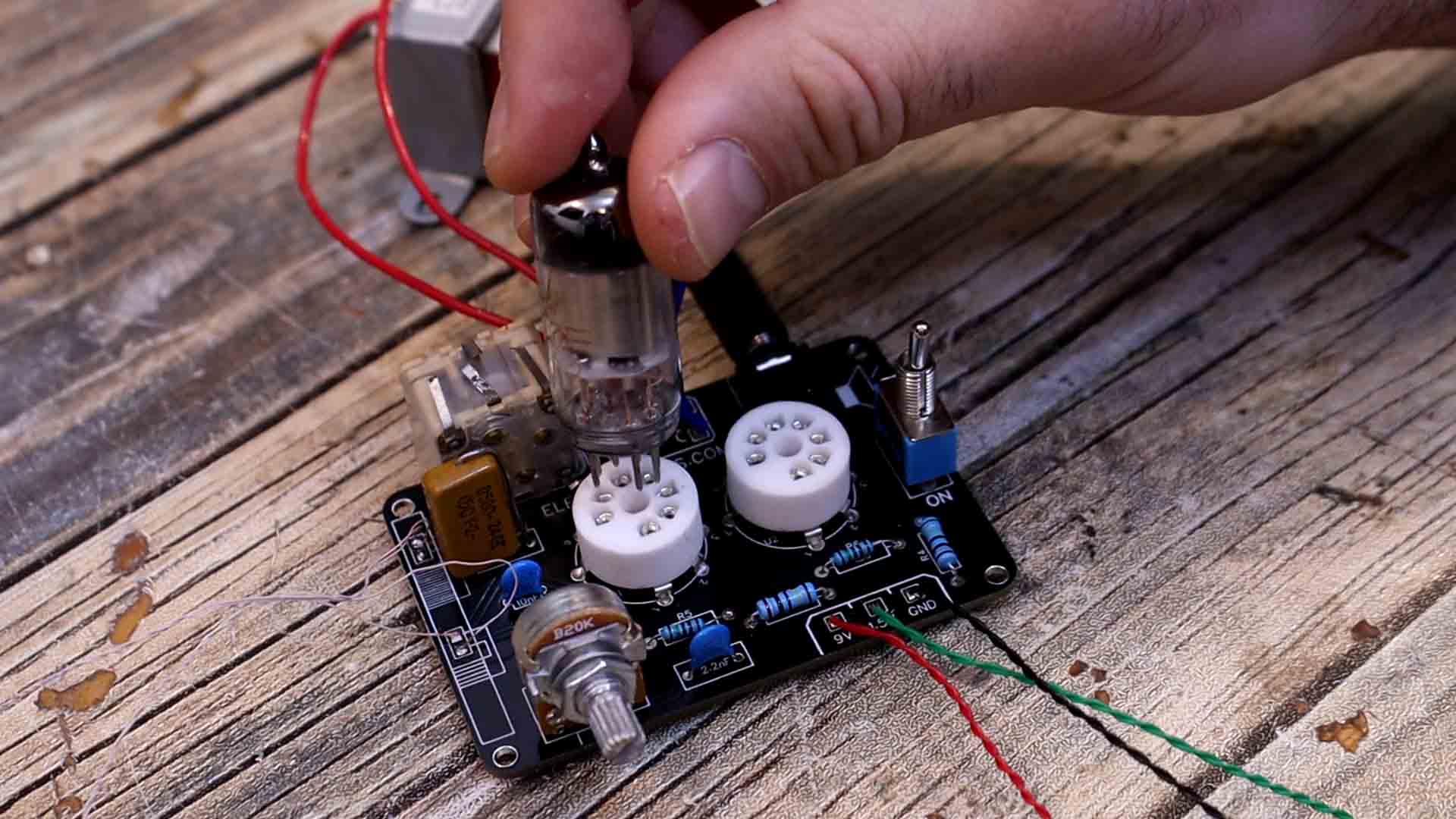
I add both tubes. For now, I supply only 1.5V and there is a consumption of around 130mA of cuurent so using a small battery can last for too long. That’s because the vacuum tubes heating filament are using a lot of current. For now, everything seems to work. Then I supply 9V as well from a different battery. And it actually works, the volume is very, very, low but it works. Here I place the microphone close to the speaker and we can hear a random radio channel.
To get higher volume I will add at the output a small PAM amplifier and check the results. The volume is now higher. But I have to say the quality is not that good.
Also, you can use an online calculator and find a good antenna size. For our frequency range we need a dipole antenna of around 10 meters if you want to listen to far away broadcast stations. You can also see in the test videos how my body is affecting the amplitude of the signal when I touch the coils, because my body is acting as an antenna. To improve this radio circuit, you can also use a multiple turns capacitor wo we would have more precision, otherwise it would be very difficult to fine tune a specific radio channel using this capacitor. If my videos help you, consider supporting my work on my PATREON or a donation on my PayPal. Thanks again and see you later guys.