Hey guys. This is a preamplifier board but is not made with transistors. As you can see below, is made out with vacuum tubes. I’ve designed this PCB and order it from PCBWAY and also ordered all the needed components in order to mount it, the tubes, the sockets, the resistors and capacitors and so on. In this tutorial I will show you how a vacuum tube works and that’s very interesting so stick till the end. Then I want to explain to you the difference between a preamp and a power amplifier and why some people want to use vacuum tubes instead of transistors. Finally, I will show you my circuit and how the pre amplifier works, then we assemble it and test it out. Sounds interesting, so let’s get started.
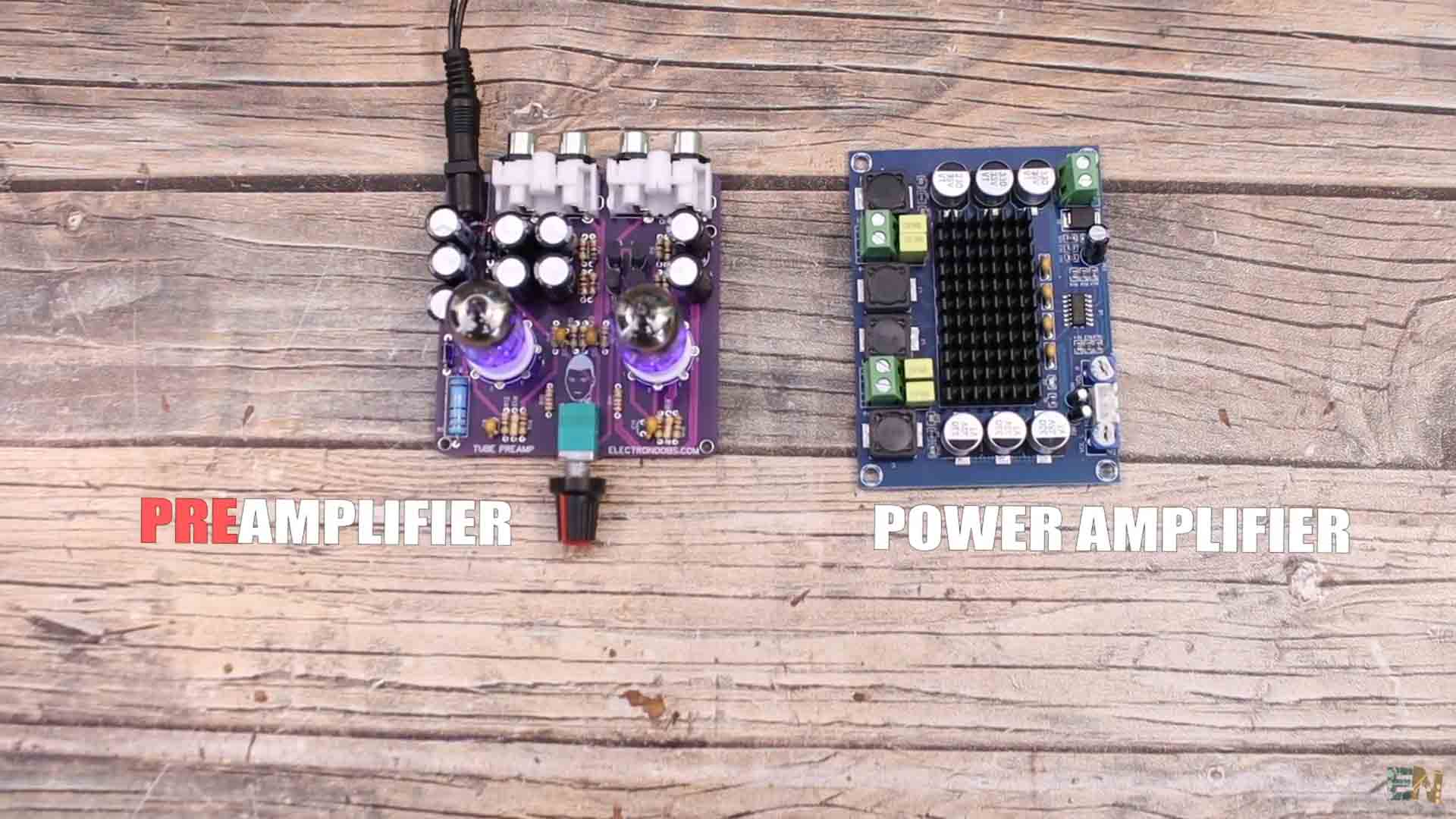
On this tutorial we make my pre amplifier PCB made with vacuum tubes. On the other side we have a power audio amplifier based on a TDA IC. The basic difference between a preamp and a power amplifier goes like this: A preamp amplifies a weaker signal such as the output of an electric guitar or a microphone, to line level, while an amplifier amplifies a line level signal so that it can be sent to powerful speakers. For example we have an electret microphone. It creates a very weak signal when exposed to sound. If we directly connect that weak signal to an amplifier, this would amplify both the signal and the noise and since the audio signal is so weak, we would get very bad results. First, we need to elevate that weak signal to line level. For example, microphone level is around -50 dBV while the line level is around 0dBV or around 1 volt, something a smartphone would give or any normal audio jack that we could then amplify. So why do people want a vacuum tube amplifier. Well, that’s because for some people it seems these tubes make the music we create sound better, smoother, warmer and cleaner and they give the audio signal some nice harmonics. And by the way, we also have power amplifiers made with vacuum tubes but these tend to be a lot bigger.
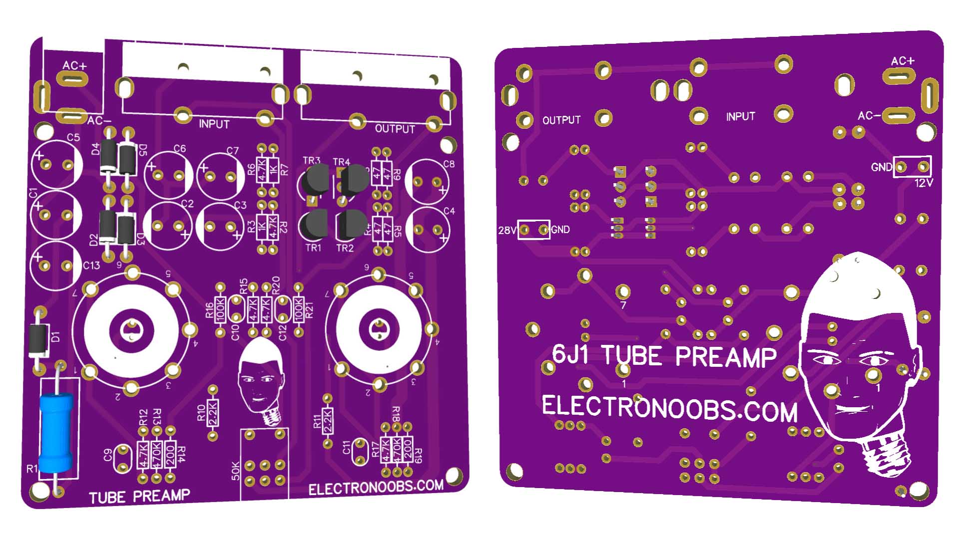
So, let’s check my PCB and the schematic I’ve prepared for today, then the part list, how a vacuum tube works for amplifying signals and finally we assemble my PCB and we test it. If you want the same PCB, download my GERBER files from a chapter below, go to PCBWAY.com for example and click the quote now button. There insert the size and the amount of PCBs you want to order. Then select a color, in my case I select purple because I think it looks amazing. Click save to cart and, on the next page, click the button and upload the GERBER files and then make the payment. In a few days, I receive my PCBs and they look very good. My PCB has an AC input for supply and on the other side we have one audio Input and one audio output for left and right channels. The AC supply is then connected to an on and off switch inside of the potentiometer. That potentiometer has two channels and also that switch integrated so we can use it to control volume but also to turn the amplifier on and off. Then, on the PCB we can see 4 diodes followed by some capacitors and 4 transistors. And yes, yes, I know I’ve told you this amplifier is not based on transistors, and is not. We use these BJTs transistors only for the voltage doubler part of the circuit.
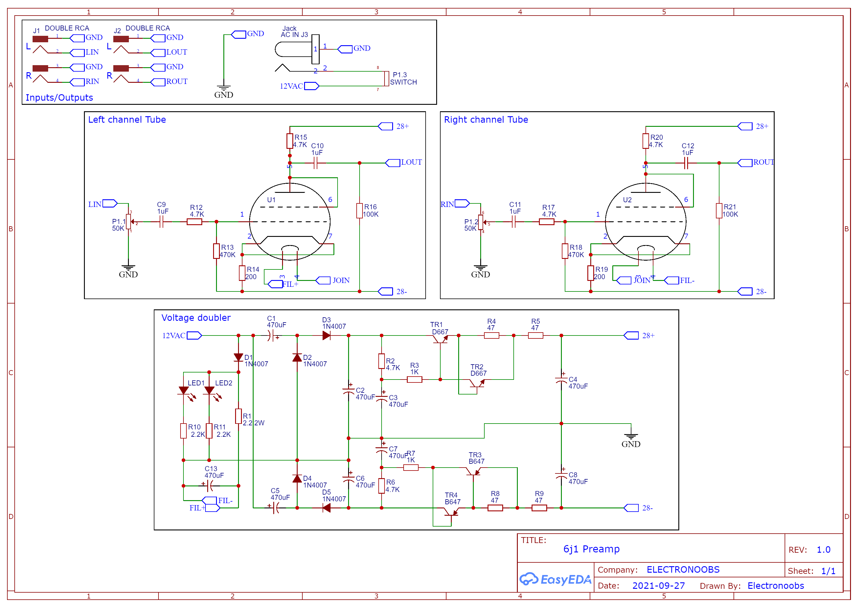
This is the schematic for the entire PCB. The bottom part is the voltage doubler that will use the 12V AC input and create 28V DC and -28V DC. We use this to supply the tubes. The 12V AC is also connected to the tube filaments which are in series and connected on pins 3 and 4 of each tube. That will heat the filaments up creating loose electrons. The potentiometer is connected between the audio input and the pin 1 of each tube. The output is on pins 5 of the tubes and connected to the RCA connectors. We ahve two LEDs each witha 2.2K resistor and those will go bleow the tubes and make them glow blue in my case, but you can use any other color for those LEDs. That's it.
Obviouslly you need the GERBER designs of my PCB that you can download from below and order the PCB. You can get all sorts of vacuum tubes but the ones I’m using today are 6J1 and this is a pentode with 7 pins. You have all the values for the components on the scheamtic above. We need the AC connector for the input and the RCA connectors for the audio. The double potentiometer with integrated switch, the resistors and capacitors, tube sockets and the tubes. Also some LEDs and the small BJT transistors. See full part list below.
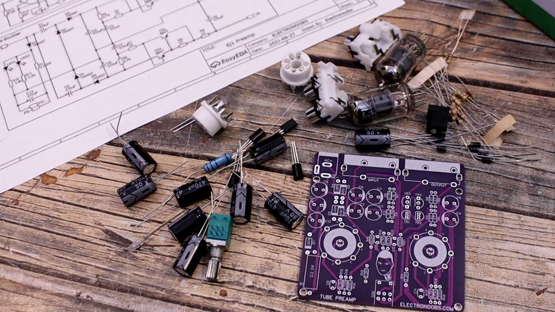
If you want the same PCB, download my GERBER files from below, go to PCBWAY.com for example and click the quote now button. You can download them for free, or if you want to help my work, buy the GERBERs from my shop for a few dollars, thank you! The PCB is 75 by 77mm size and you can select any color for the soldermask when you order the PCB. In my case I wanted the purple color. All components are through hole and on the top side of the PCB. The silklayer will show you the component number and value so is easier to solder.
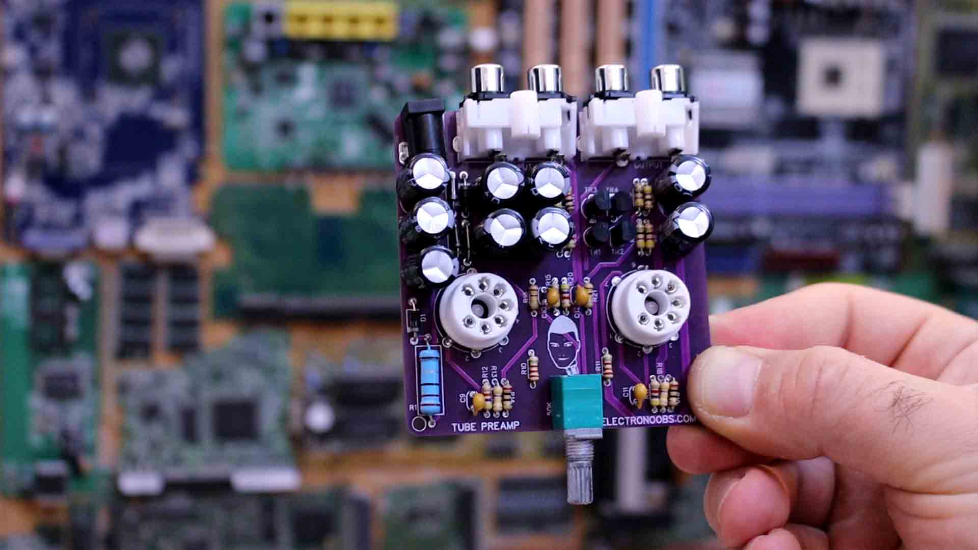
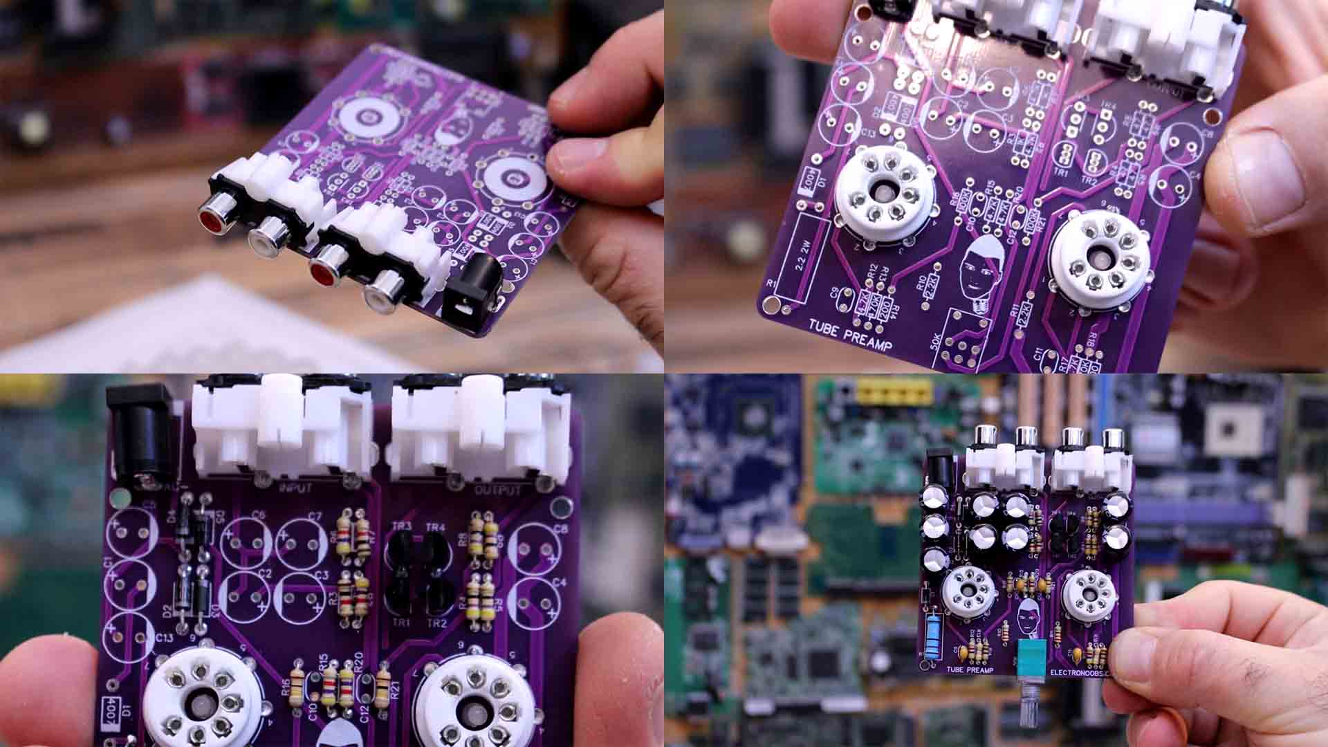
Now let’s assemble my PCB and if you want to make the same amplifier, you have all you need above. I start by adding the input connectors. First, I solder the AC input jack. Remember, this PCB needs 12AC supply. It can’t work with DC. I also solder the audio input and output connectors. Before we add the vacuum tube sockets, we need to solder some LEDs below. These will glow through the tubes and give them a cooler look. Then we can solder the vacuum tube sockets. We use these so we don’t have to solder the tubes directly to the PCB. Then I also add the volume potentiometer and on and off switch. I add the power resistor for the heating filaments of the tubes and this must be a power resistor of at least 2 watts. I add the rest of the small resistors. Finally, I add the diodes and the BJT transistors and make sure you don’t solder them backwards. Last components to be soldered are the capacitors and in my case, they are a little bit too big but they still work. Everything is soldered so let’s test if it works. Finally, I add the tubes to their sockets.
To supply the PCB, I will use a 12V transformer that I have from some halogen lamps and this has no rectifier at the output so we have AC voltage of 12V and 4 amps. I connect this transformer at the AC input and we can see the blue LEDs below the tubes are now glowing. Since the preamp doesn’t have enough power, I add my amplifier between the preamp and the speaker. Like this we can have decent power but the soft harmonics and effects of the tubes. I get the music from my smartphone. First thing I’ve noticed is that once you turn it on, it will take a few seconds for the sound to start because the filaments inside the tube must heat up. Take a look, I turn it on. And we have to wait and the volume will slowly go up.
I don’t know about you but I can really hear those harmonics as an echo after each sound peak. The pre amp works. So guys, that’s how I’ve made my own tube based pre amplifier. What do you think? Is quite interesting, right and it should give your music more harmonics and a smoother sound. You have all that you need to make this project above. If my videos help you, consider supporting my work on my PATREON or a donation on my PayPal. Thanks again and see you later guys.