This below is a Tesla Coil and it plays music with plasma. And I bet that you wonder, if it is a Tesla coil, where is the coil? You would expect a copper coil with a huge amount of loops. Well, this Tesla coil has its windings in 2D, meaning the windings are on the flat PCB. That’s right, using the services of PCBWay I was able to manufacture these very thin coils covered in gold for more conductivity, with over 180 loops, so it creates high voltage. In this post I will show you the schematic and what you need, we assemble the controller PCB, and then we connect the coil PCB and test out its power. It will get shocking, pun intended. I will also show you how it works and how to add Bluetooth music to it.
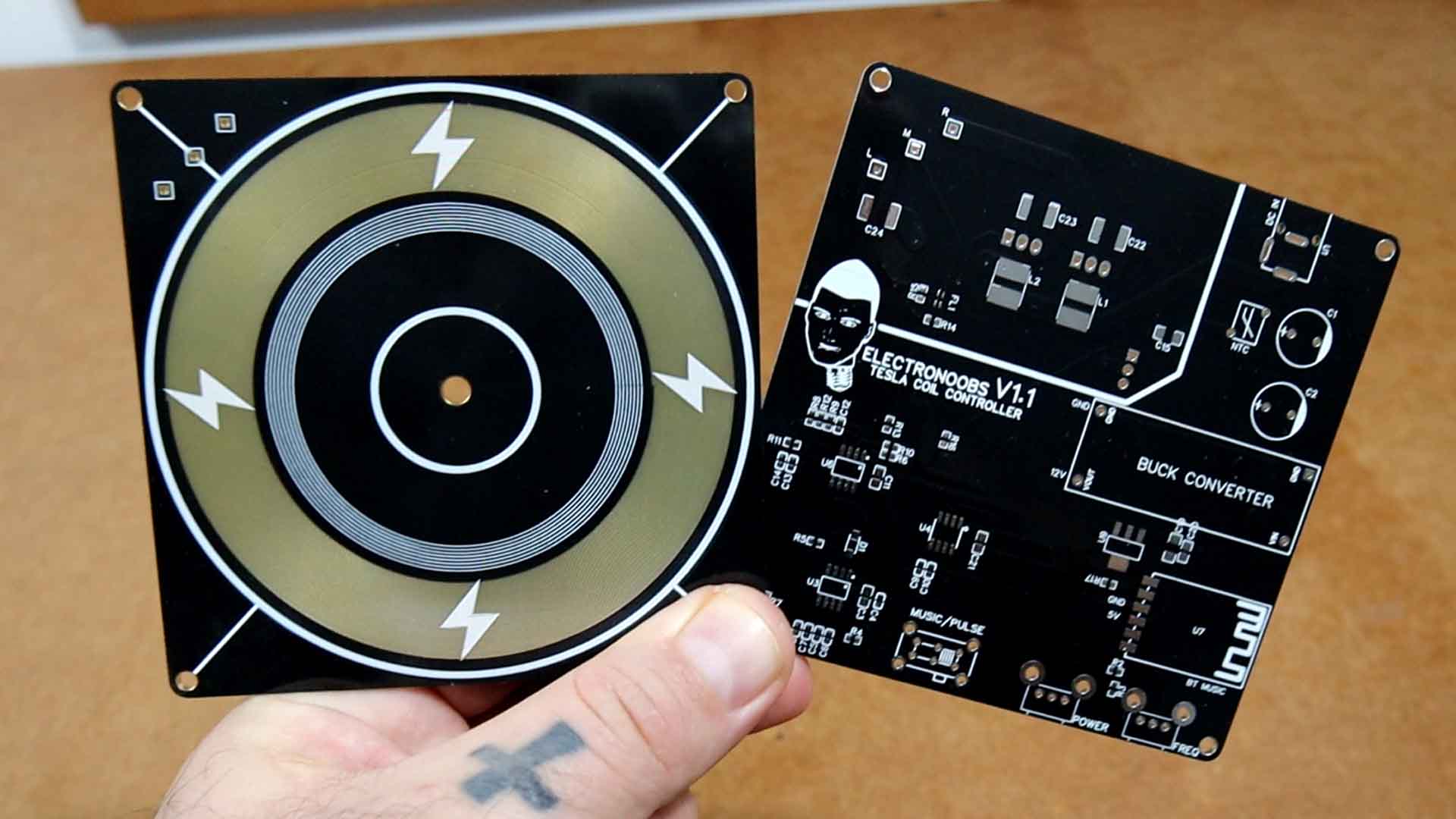
What’s up my friends, welcome back. Let’s start by checking the schematic, the PCB, parts we need and finally we assemble it so you will understand how it works. For this project I’ve made two PCBs, one for the power controller and resonator and the other one is just a coil. We need to keep them separate since the coil will create thousands of volts and the arcs could jump to the other PCB and burn the components. For the coil PCB, in order to have better conductivity, I’ve asked PCBWAY to make the tracks covered in gold. As you can see in the video, it looks awesome. The windings are only on the top side of the PCB but on the other side we have just one loop.
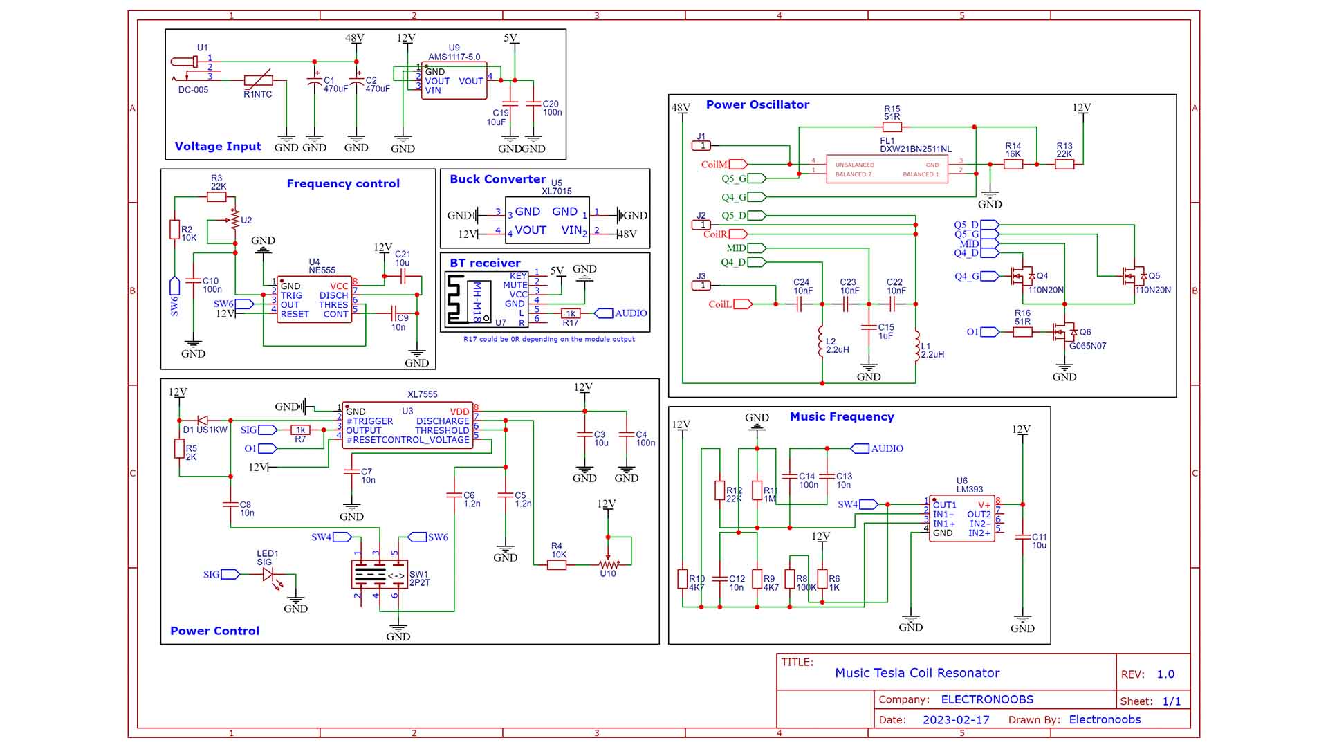
For the power contol PCB we have this schematic below. We have timers, comparators, power regulators and so on. We start with 48V input, then a buck converter to get 12V for the timers and then a 5V LDO for the Bluetooth module. The 555 timer creates pulses and using the potentiometer U2 we control the frequency. The 7555 timer controls the power with the U10 potentiometer. The output signal "O1" is connected to the Q6 MOSFET creating pulses and making the LC tank resonate. The LC tank is made with 2 colis (L1, L2)) and 2 capacitors (C23, C22). That's how we create the pules at the primary coil and get high voltage on the secondary.
The switch SW1 can change from the 555 frequency or the music frequency. The music is received with the Bluetooth module and passed to pulses using the LM393 OPAMP.
For this project I’ve made two PCBs, one for the power controller and resonator and the other one is just a coil. So download the GERBER files from below and go to PCBWAY.com Click the quote button and add the size of the PCB and the amount. In my case I order the black soldermask since it looks great. Save to cart and on the next page upload the zip file with the GERBERs. After the confirmation, place the order and receive the boards in just a few days. Ok, so now we have the PCBs and they look awesome. Especially the top one with the golden coils. The tracks are only 0.14mm thick and 0.15mm clearance. If you check the PCBWAY capabilities page, you can see that they are more than capable of making very fine tracks without problems. There are more than 180 loops on this PCB.
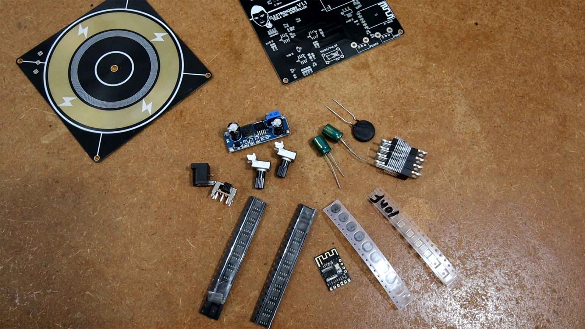
So now we know the schematic and we have the PCBs. I gather all the needed components and you have a full part list below. The main input will be 48V from a DC adaptor. So I get a buck converter to lower the voltage to 12V for the ICs. Then I also add an AMS1117 for 5V for the Bluetooth Receiver. I get the passive components such as resistors, coils and capacitors. And finally, we need two timers and the LM393 OPAMP. Also connectors, potentiometers, a switch, etc.
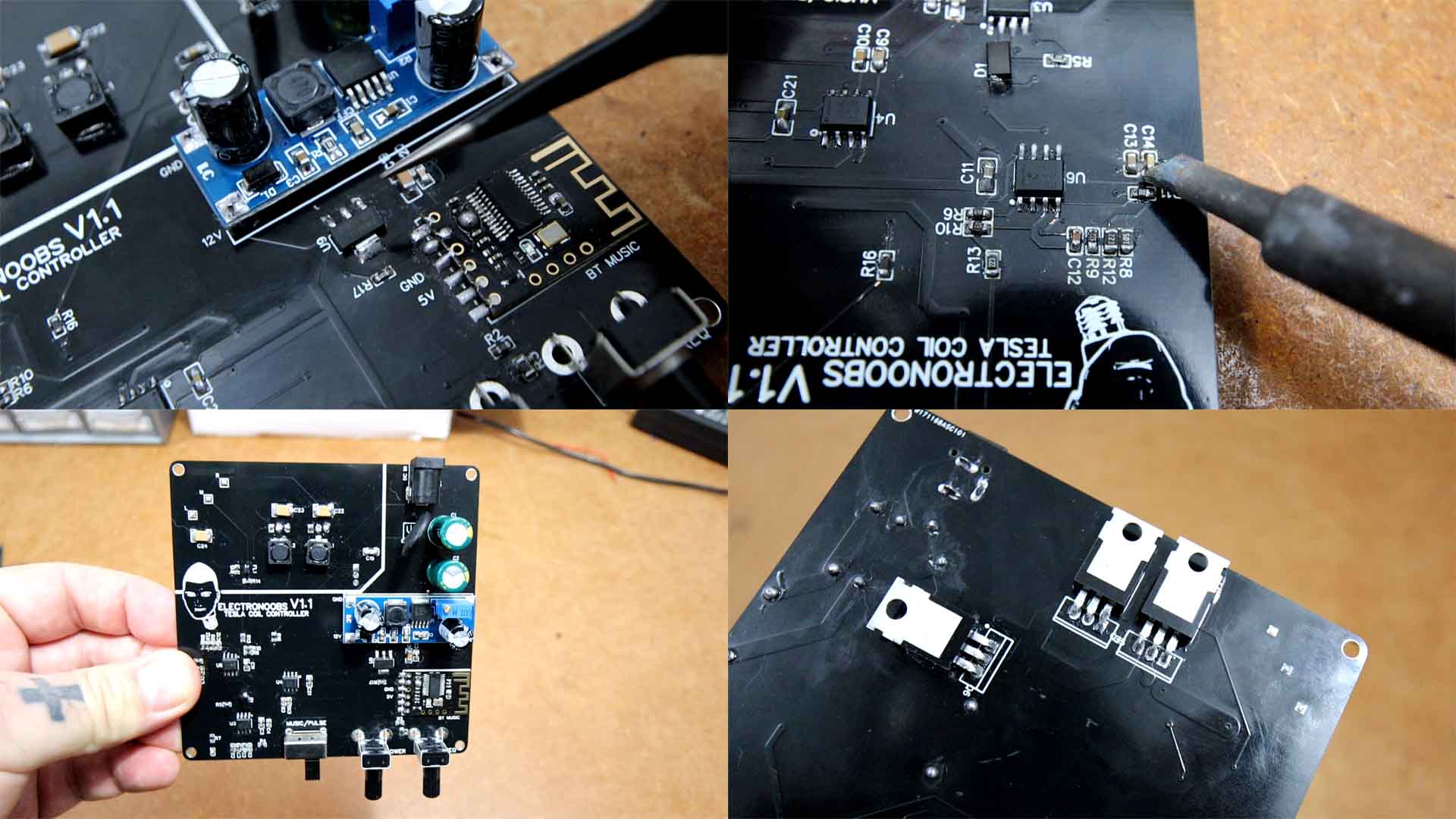
I solder all the components and it was a mess. Because making tests I had to desolder a lot of capacitors and try different values to get the resonance. Actually, I’ve soldered the board two times because the first time I burned the converter and the 48V got to the rest of the circuit and burned everything. The power MSOFETs were palace on the bottom side for a reason. Like that we can bend them and we can add a heat dissipator. If you use them for some time they might get really hot so we must add a heatsink for longer use, that's why all 3 MOSFETs are facing up with the metal pad facing down. Use thermal pads and add some sort of heat dissipator.
I start by soldering the DC jack, 470uF capacitors, NTC and the 12V buck converter. I supply the board and test the 12V value. THen I add the 5V regulator and its capacitor and measure again the value. If is ok, I solder the rest of the components in no specific order.
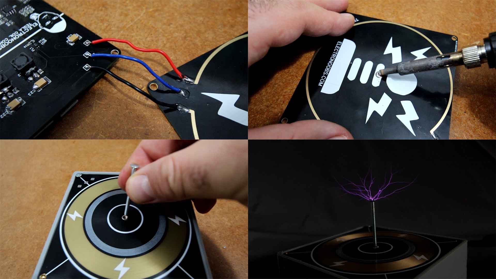
I use some solid wires and connect the power board to the coil. They have the same markings so it is easy to know where each wire goes. In the middle of the coil PCB I have a 5mm via. Here I could solder a brass insert with an M3 thread for screws. I power the board with 48V from a DC adapter. I increase the power and there you go, we have a working tesla coil. Amazing sparks are coming out of the screw. I can also change the frequency with the other potentiometer. Looks quite cool right, and is also very powerful, let me dim the lights so we can better see the sparks.
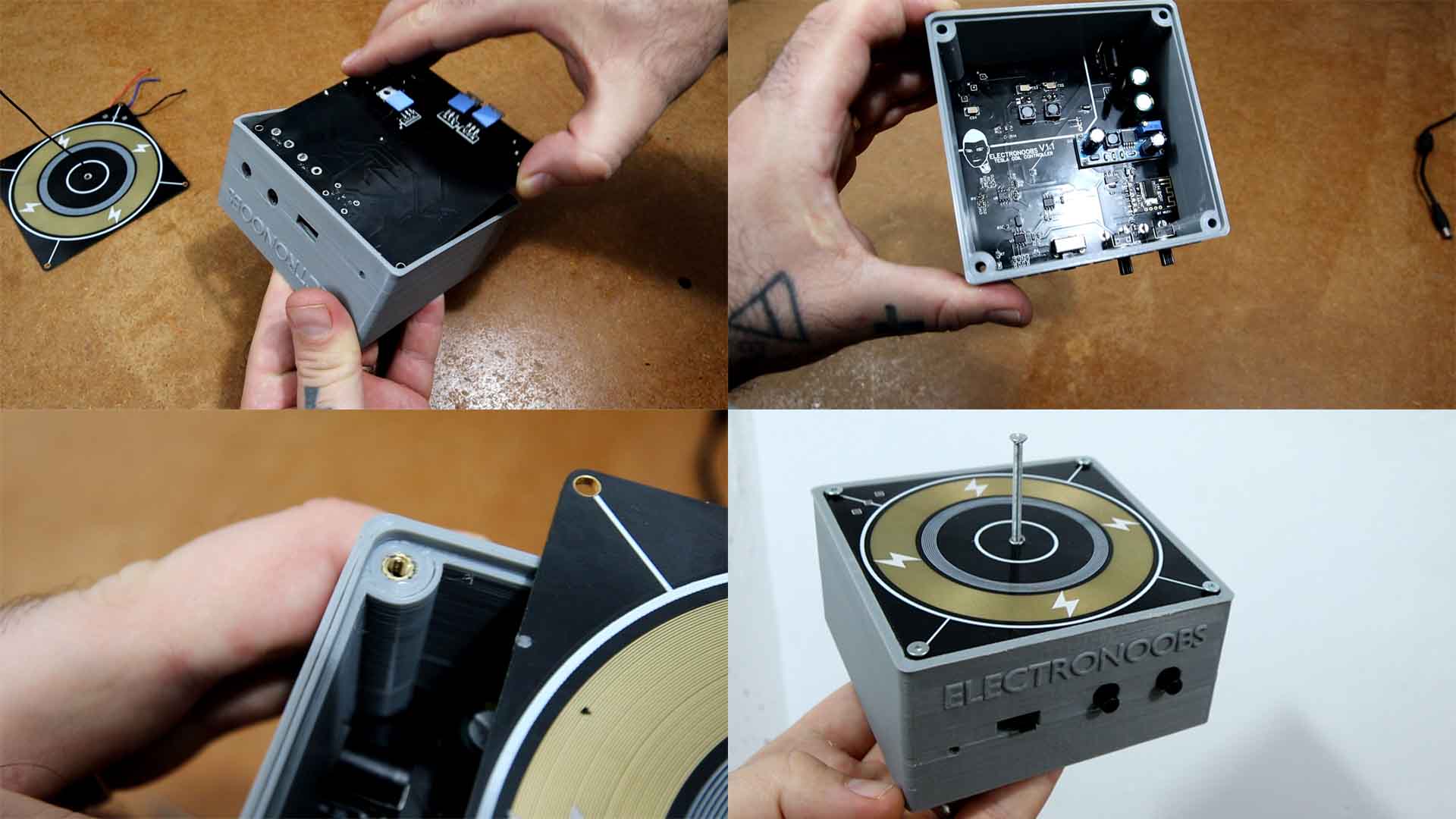
But we can also add music, right? But first, because it looks a bit ugly like this, I’ve created a case for it and 3D printed in PLA. The controller board goes below and the coil above. In this way we can add a heat dissipator below the 3D case. I add those insertion nuts with my soldering iron and then I can close the coil PCB with screws. Now it looks a lot better, right?
You have everything you need above, for the schematic, the GERBER files for the PCB and the part list if you want to make your own tesla coil or even improve this one for more power. In my case I want to use better inductors, thicker tracks for the coil and more loops and increase the power even more. To learn how a tesla coil works, check my previous videos on such devices and see how it creates the high frequency and high voltage sparks. If my videos help you, consider supporting my work on my PATREON or a donation on my PayPal. Thanks again and see you later guys.