
This is a component tester made with Arduino. Is not the same as my multimeter. I mean, It still measures values but in this case it measures component values: transistors, diodes, resistors and capacitors, inductors and more. It could measure components with 3 pins and tell you different information about each component. If it is a mosfet or a BJT, its on resistance, the polarity of a diode, the capacitance of a component and so on. Later we will see some tests with different components. The original Ardutester was made by Karl Heinz and since then it had all sort of versions. I’ve place a link for the original project and this project below in the description. But let me show you the PCB I’ve made for this project, what we need to assemble it, how it works more or less and test it on different type of components. So, let’s get started.
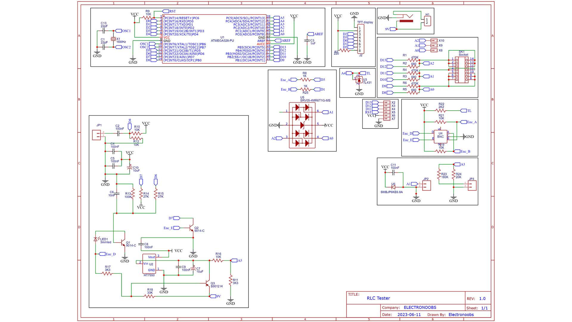
What’s up my friends welcome back. To make this project, with this original schematic and other versions I’ve found online, I’ve made my PCB. Is based on the ATMega328 microcontroller, the same as the Arduino UNO. It has these parts. A display to show the values, 3 pins to connect the component, a power input pin, and some extra connectors for PWM signals, frequency meter and so on.
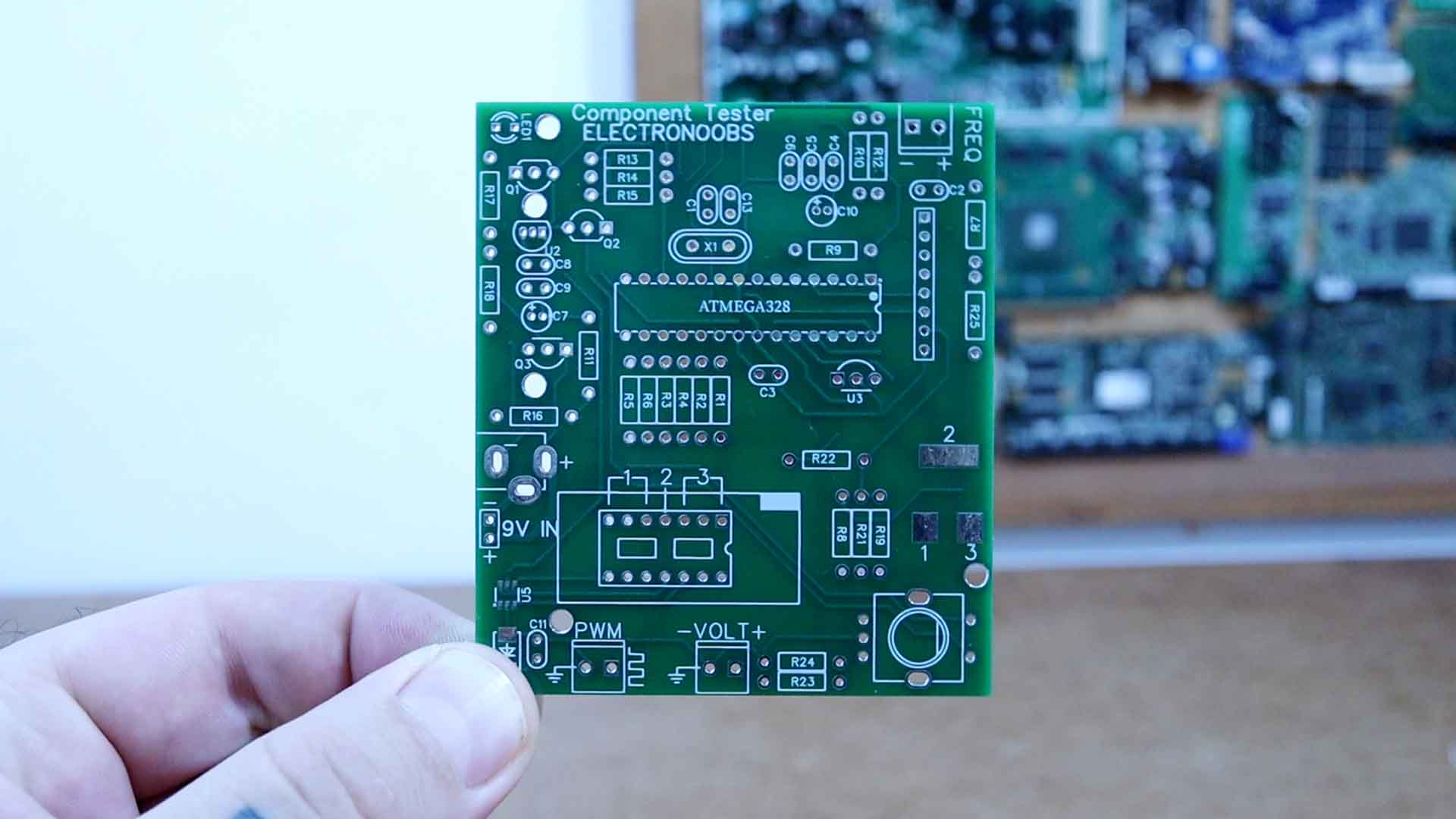
Get the GERBERs for my PCB design from below for free. Then you can go to PCBWAY and order the PCB by clicking the order now button. I add the settings for the size, the amount of PCBs and the color. In my case I select the green color and I save to cart. On the next page upload the GERBERs you’ve just downloaded from the link below. Place the order and get the PCBs in just a few days. They look very good so PCBWAY once again did a good job. Is time to assemble the board.
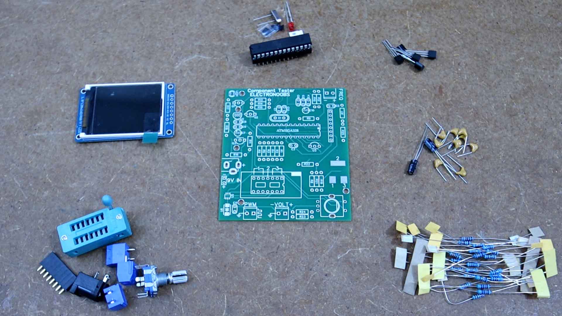
The list of components is a bit long but nothing special. Resistors, capacitors, connectors and so on. The main parts are the ATMega chip, the TFT display, the rotary encoder and connectors. We also have some voltage regulators and transistors. Check the full part list below.
Let’s start assembling it. Download from below the full schematic and use the same values. First I add all the capacitors using the values on the schematic. Then I do the same for the resistors. I’ve used through hole components so it would be for you easier to solder. Before we add the sensible components I add the voltage regulator, the BJT transistors and the TL431 diode. I add the input power jack and the other connectors. I wanted to test the VCC voltage with 9V from my supply but without the microcontroller, the BJT transistors are off so we can’t measure the VCC and see if is 5V or if it would burn the controller.
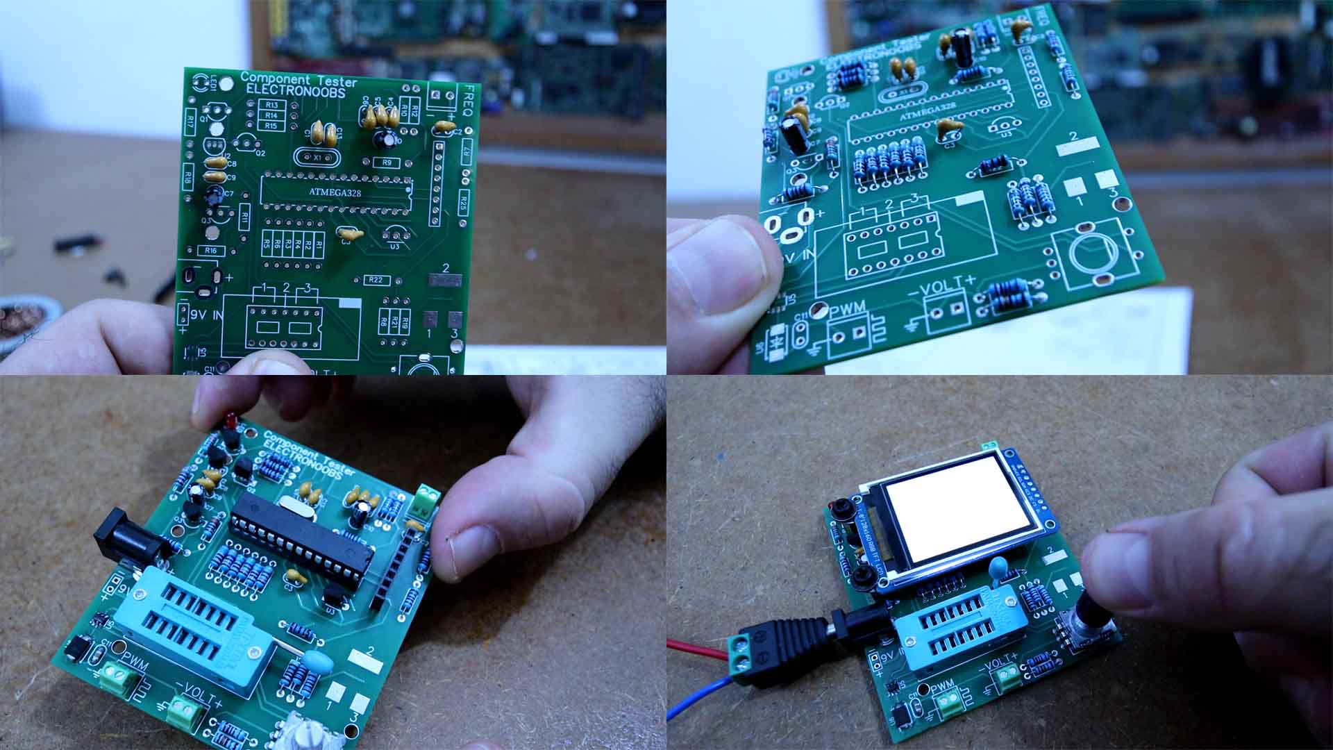
Anyway, I solder the final socket for the microcontroller and a row of female pins for the display. And for the component input I will add this DIP socket. On the PCB you can see we have 3 inputs, pin 1, 2 and 3. And we have those same inputs for SMD components with these pads, again, 1,2 and 3. Finally we add the microcontroller to the socket. And for the display I’ve used this one with the ST7735 chip that only costs you a few dollars on AliExpess and is easy to use with the SPI connection.
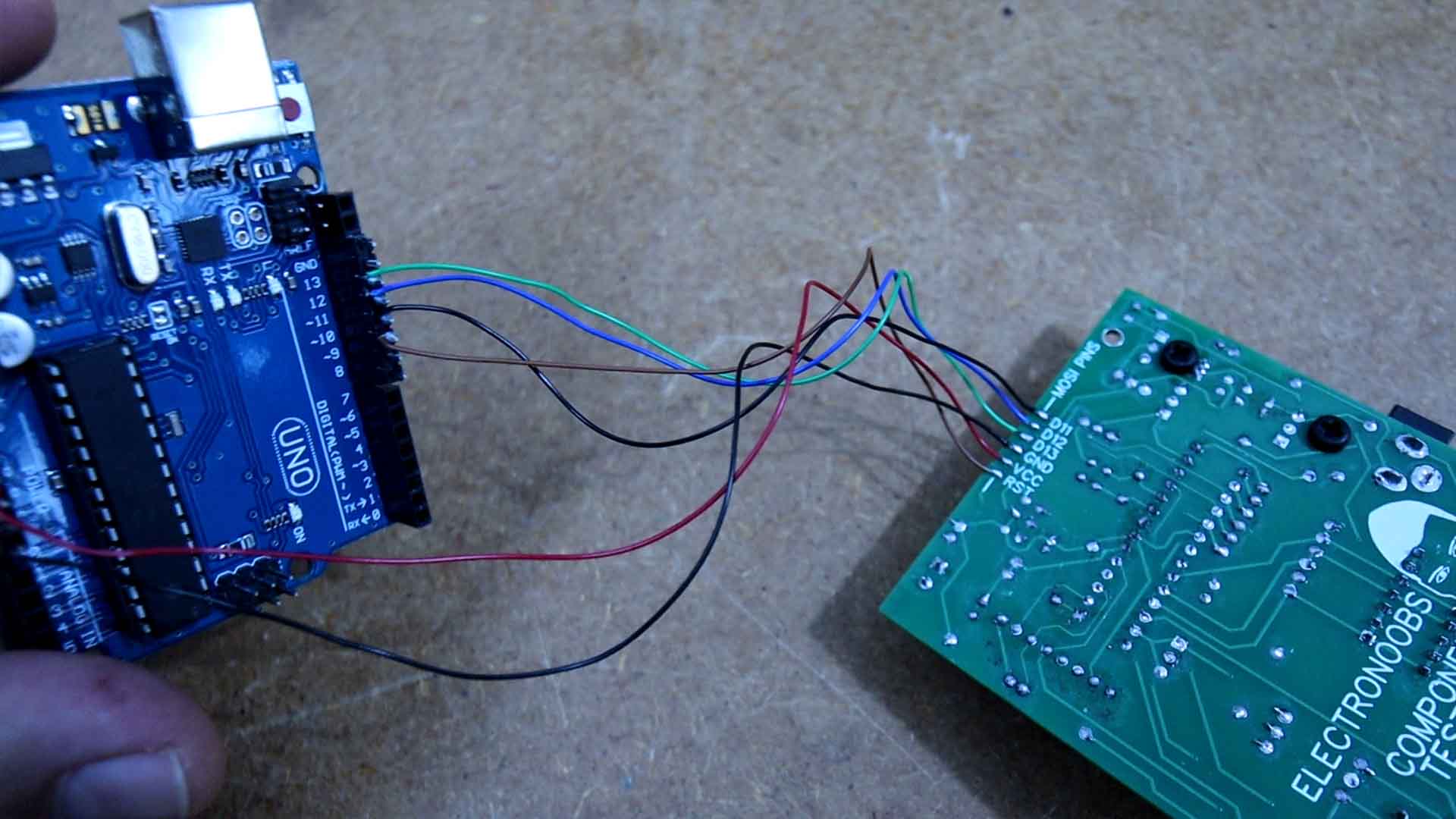
And once again a huge thanks to the involved people for the original ardutester code and you can also check the updated code on this page. Download the zip file and open the original code. I will use AVRdudess to upload the hex and eeprom files and also to write the fuses. On the back of the PCB we have the ISP pins for programming. Get another Arduino UNO and connect it to your PC. Open Arduino IDE and go to examples, Arduino as ISP and open this example. Compile and upload it to the Arduino UNO and now it should work as an ISP programmer.
Now connect the Arduino UNO to the tester PCB like this on the SPI pads on the back. I’ve used thin wires for that. Connect back the Arduino to your PC and now open AVRDUDESS which is a free software. As programmer select Arduino and this baud rate. For MCU select the ATMega328p and click detect and it should detect the ATmega chip. Download the HEX files from below or from this github repository where you have the original version and two other versions. For flash select this HEX file. For the EEPROM select this epp file and for the fuse open the fuse file and copy these values. Then click “program” and the code will be uploaded.
Extra, we could design and 3D print and enclosure for this PCB to make it last longer and look a lot better. Feel free to improve it as you want. So guys, that’s how easy is to make a RLC and transistor tester. Get my GERBER files for free and the code together with the part list and schematic from above and also check the original links. Using PCBWAY create your own RLC tester and use it for your projects.
If my videos help you, consider supporting my work on my PATREON or a donation on my PayPal. Thanks again and see you later guys.


