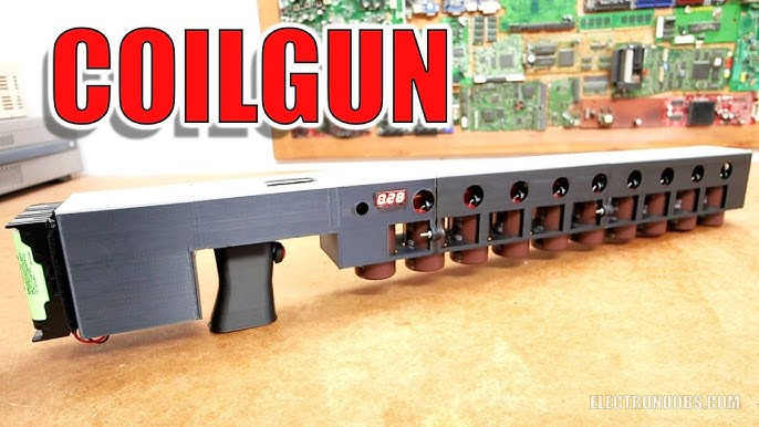
This, is version 2 of my very powerful coilgun. As you can see, is huge and it has quite some power and works with high voltage, so please, I can’t stress this enough. Never touch the high voltage parts, stay insulated, use proper tools and if you don’t know what you’re doing, don’t try this project, just watch the video for learning purposes. That being said, in this video I will show you the improvements from the previous version, I will rectif
by: ELECTRONOOBS on 2026-06-02
Please also check VERSION 1. This is the schematic for this project. Basically, we have the first stage which is a bit different and then the second to the tenth stage is all the same. The first stage is different because it has the push button activation, the 450V input and 12V. The rest of the stages are using infrared light to trigger the magnetic field so they don’t need the push button part. In Altium designer, I update the PCB and start placing the components. There are a lot of them but since the stages are all the same, is a very repeating process. All you have to make sure is that the distance between the coils on the PCB is 45mm and for the infrared LEDs as well. The LEDs that have the arrow must be face to face because these are the detectors.
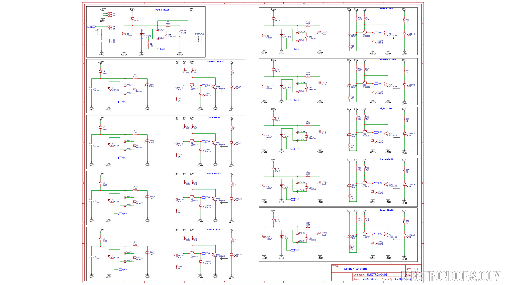
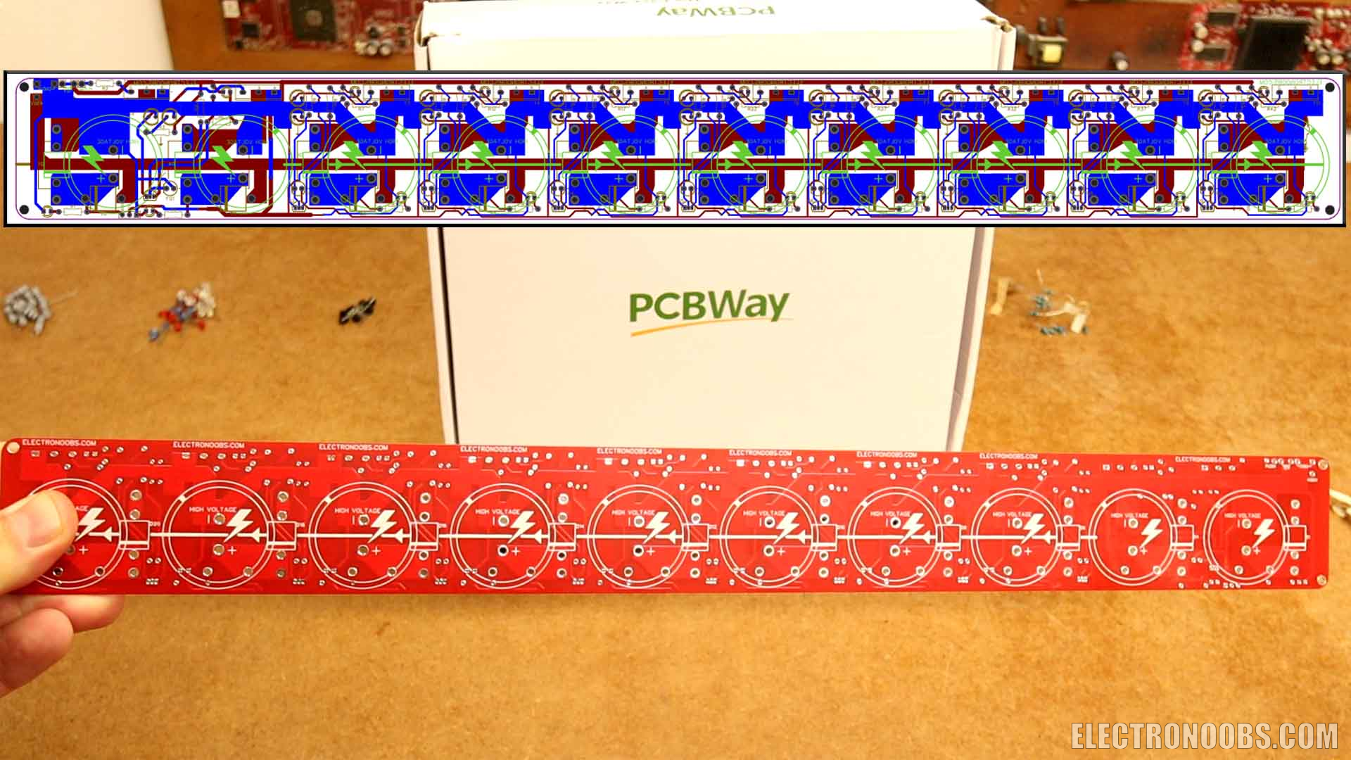
For the high voltage tracks ground and 450V, I use very thick tracks in order to withstand enough power (>4mm width). And then, the rest of the tracks for signal and 12V, are using just 1 mm tracks. And that’s it, the PCB is ready, but this time with 10 coils and it has a size of 47 cm long by 5 cm.
Or maybe support me by buying the GERBERs from my shop.
I generate the GERBERs and go to PCBWAY.com. Insert the PCB size and click quote now button. Here I select the red color for the soldermask. I add to cart and on the next page I upload the GERBERs generated with Altium. Submit the order and receive the PCBs in just a few days. They look awesome. I know that the black finish is my favorite but I also like the red color, it looks great, right? So, if you want to try my project, download the GERBERs for free.
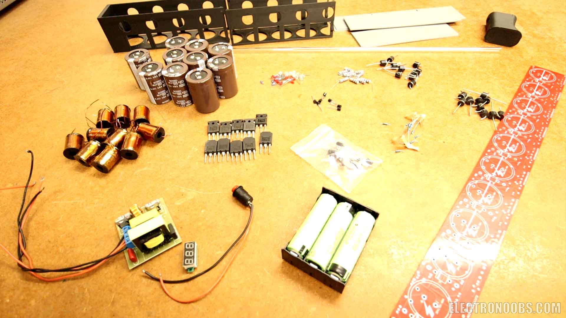
Is time to solder. We have 10 coils, 10 thyristors, 10 huge capacitors, there are 450V capacitors. We need 10 infrared LEDs and detectors, 20 huge diodes, resistors, LEDs and so on. We also need the high voltage generator, a push button and a battery pack for 12V. The full part list is below.
- PCBs GERBERs Download Here
- 3D Files for the case Download Here
- 1 x 400V generatorLINK Aliexpress
- 1 x 18650 battery socket LINK Aliexpress
- 1 x 18650 battery LINK Aliexpress
- 1 x push button LINK Aliexpress
- 1 x voltage indicator 500V LINK Aliexpress
- 10 x coils LINK Aliexpress
- 10 x 70TPS12 Thyristors LINK Aliexpress
- 10 x 450V 680uF Capacitors LINK Aliexpress
- 10 x 100R 1W resistor LINK Aliexpress
- 10 x IR detector pair LINK Aliexpress
- 10 x 6A10 diode LINK Aliexpress
- 10 x FR607G diode LINK Aliexpress
- 10 x S8050 NPN transistor LINK Aliexpress
- 10 x 3mm red LED LINK Aliexpress
- 10 x 3mm blue LED LINK Aliexpress
- 10 x 3mm white LED LINK Aliexpress
- 1/4W resistors (check values on schematic) LINK Aliexpress
- 1 x acrylic tube LINK Aliexpress
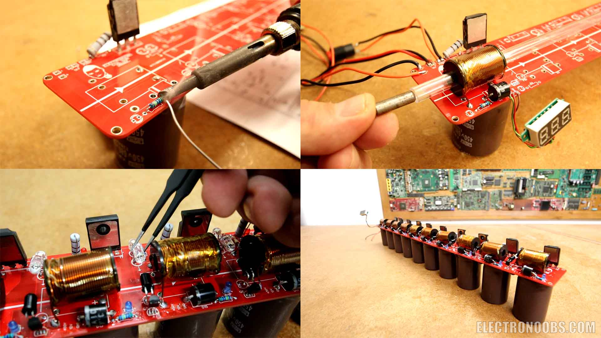
I start with the first stage and adding all the components will take some time because there are a lot of them and since the copper is so thick, it requires a lot of heat and my soldering station can barely do it. And is a powerful station, but the heat dissipation is too high. Another improvement from the previous version is the barrel. This time, instead of a metal one I use a plastic one. In this way there is a lot less friction and the magnetic field is not wasted on the metal of the barrel so is a win-win. Also, since is transparent, we don't have to make holes for the infrared LEDs each 45mm as on the PCB. The first stage is ready. I connect the 450V generator and the push button. Supply the gun with 12V and charge the capacitor. I test it out with a projectile and it works great. So I can solder the rest of the stages which are all the same. Just make sure the LED and sensor are face to face. Since it is so repetitive I won’t show the entire process. I had to salvage parts from my previous version, especially the copper coils since those are a bit expensive. If you don’t want to buy them, you could 3D print my design and then use enameled copper wire to create your own coils.
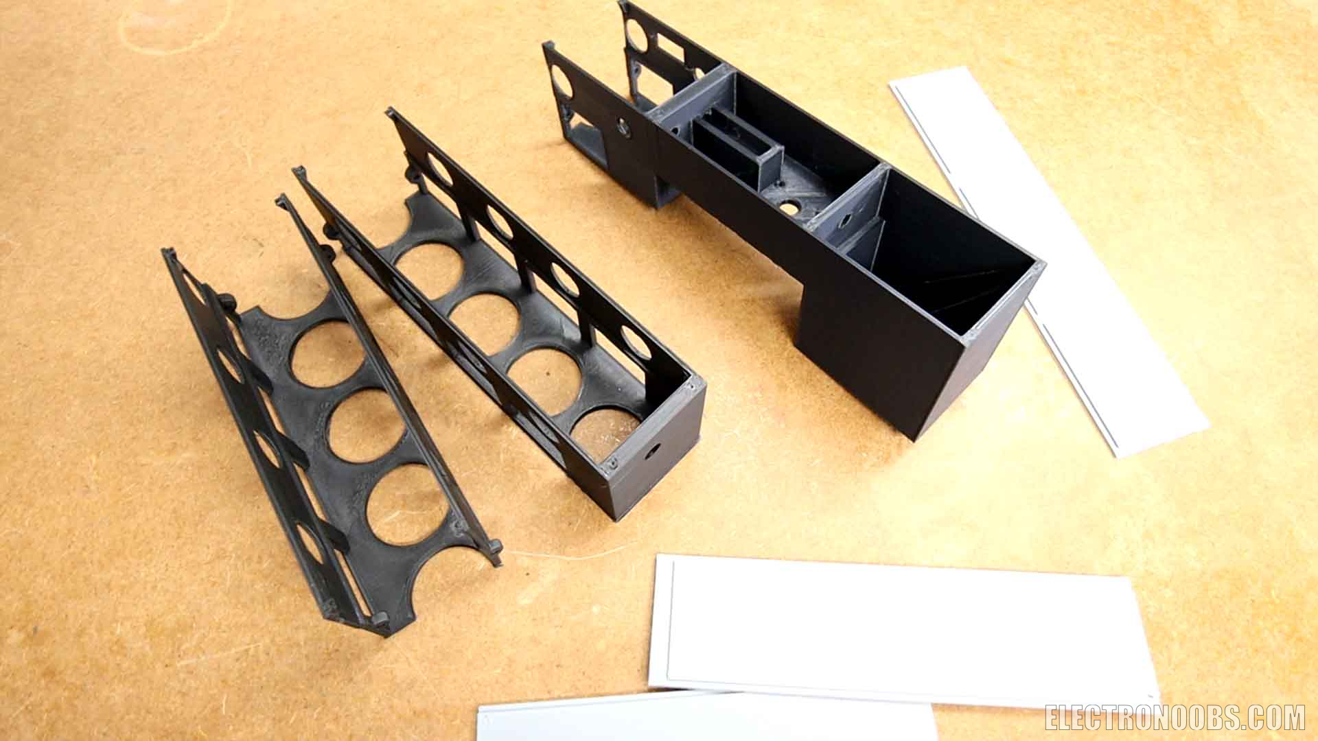
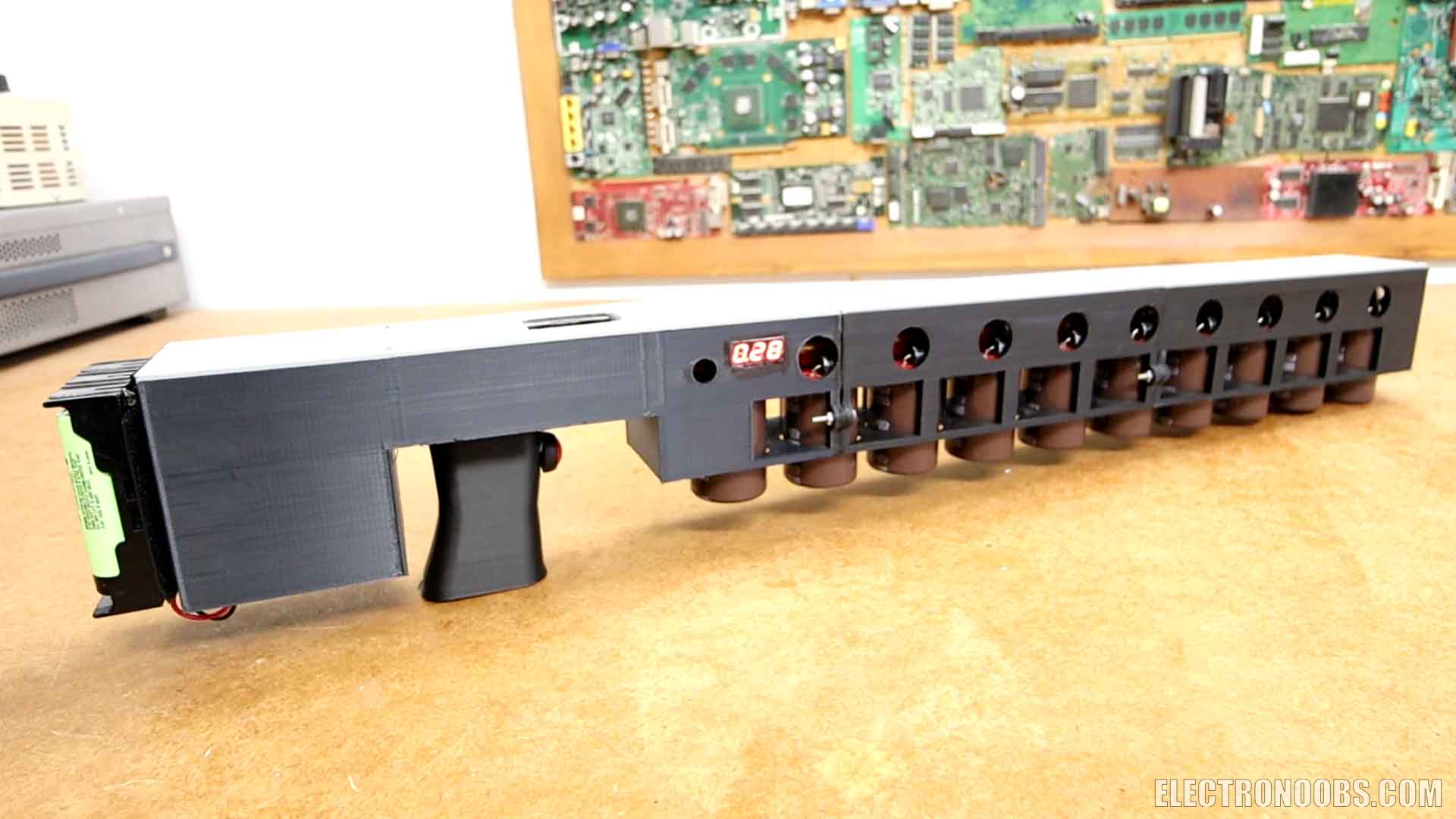
As a final step, to make this look cooler I’ve designed a 3D printed enclosure. Actually this will also add some safety since the high voltage is kept inside. I’ve made the case with 3 main parts that will join together by screws, 3 top parts and the trigger. Inside the trigger we can add the push button. I merge together the 3 main parts with screws and super glue. All parts were printed with PLA filament. The case has screw holes for the PCB so, I carefully add the coilgun inside the case and use small screws to fix it in place. I pass the wires to the back compartment where the generator and battery will go. The voltage indicator is on the side so we can see the charging process. I also add two toggle switches for 12 and 450V. Unfortunately, the generator and the battery pack can’t both fit inside the case. So maybe I will add the generator inside and the battery here on the exterior. I will use Velcro to do that. So, finish the final details and like that the coilgun is ready. It looks better than the previous version but the 3D design could still be improved.
Ok, the gun is ready and all the capacitors, coils and so on are soldered in place. It looks awesome, right? To test if the sensors are working, just supply 12V and pass with an object in front of each pair of infrared sensors and the red LED should light up like this. Look how they light up in series when I insert this rod. But once again, please don’t try this if you don’t know what you are doing. The PCB has input for 450V, 12V and the push button. I get the high voltage generator and I connect it at the 450V input. Turn on the charging princess by connecting the battery pack. On the side there is a voltage meter so you can know when the capacitors are fully charged. Now that is charged to over 400V, I add a metal projectile and fire. Wow, how much power. It went through the plywood without any problems.
So guys, this was the update for my new coil gun now with 10 stages all together. You have the previous version here as well and all the needed files to complete such a project, the schematic, the GERBER files for the PCB, the part list and a full tutorial on this post. Please be careful and don’t play around with high voltage or fast shooting projectiles. Take this project for learning purposes. If my videos help you, consider supporting my work on my PATREON or a donation on my PayPal. Thanks again and see you later guys.
Comments


Leave a comment
Please login in order to comment.