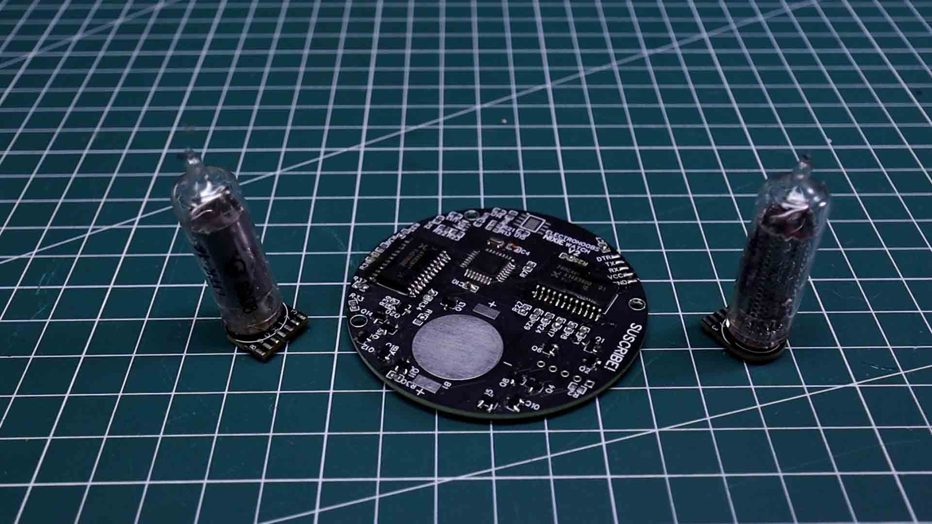
What I’m holding in this video is nearly 70 years old. It’s a relic from the height of the Cold War, straight from the heart of the USSR. The box even smells like 1950s communism or some secret bunker. That is a Nixie tube. It doesn't use LEDs or pixels; it uses glowing neon gas and metal. But to make it shine, you need more than 150 volts. And I’m crazy enough to try and strap that high-voltage history to my wrist. Let's get started.
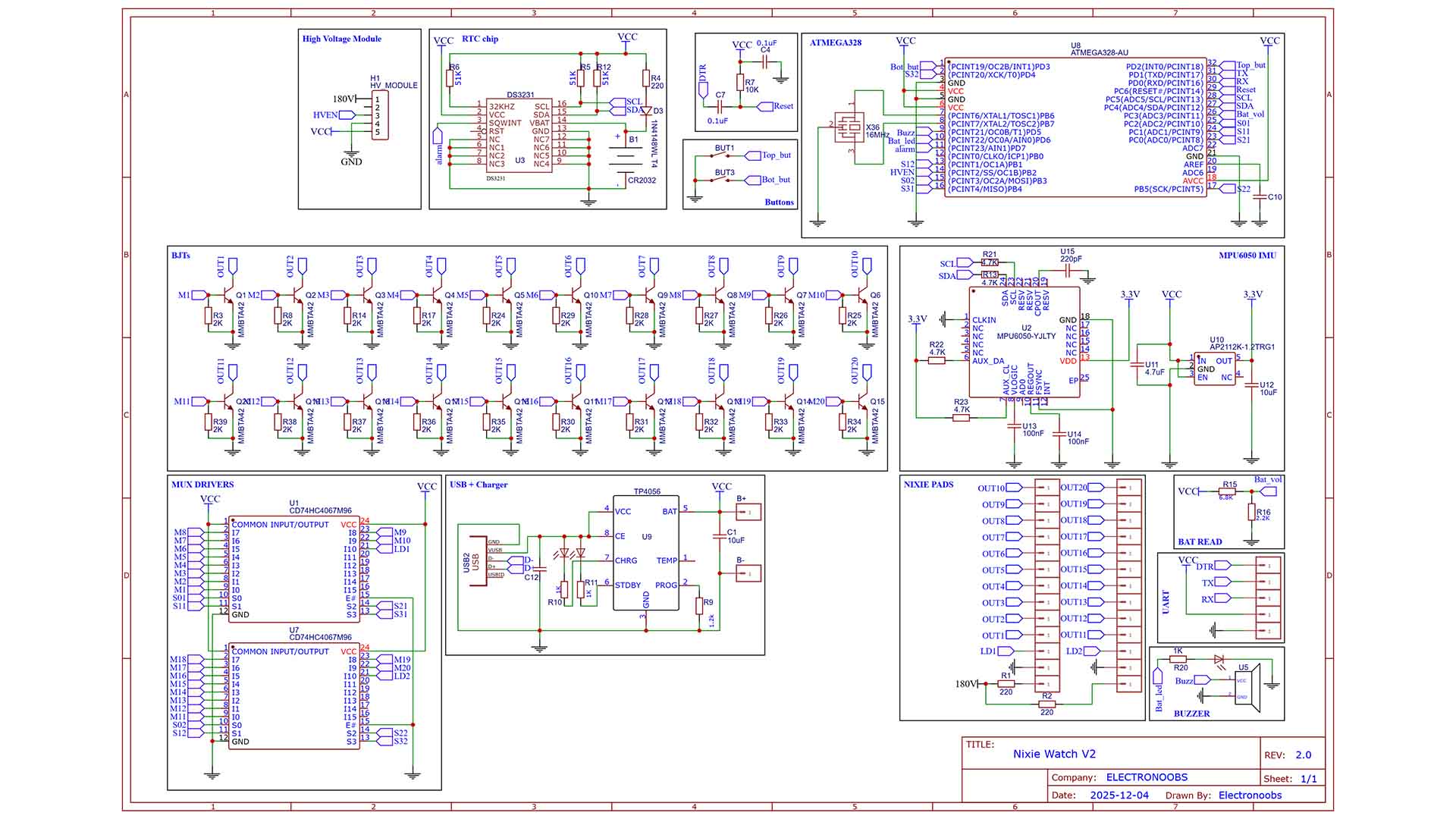
Let's see what parts I've used. I had to solder twenty individual BJT transistors. One for every single digit. It’s more work, it takes a bit more space, but it’s the only way to ensure 150V doesn’t end up frying the 'brain' of the watch. And to power it all, I’m using a tiny module—just 15 millimeters wide. It’s the high-voltage heart. To control the BJTs, since the ATMEGA chip doesn't have enough pins, I'm using 2 MUX drivers. For the time I'm suing a DS3231 RTC IC. It also has an MPU6050 IMU for hand movement detection and a TP4056 charger IC for the battery. The rest are resistors, capacitors, buzzer, cell battery, and some other small components.
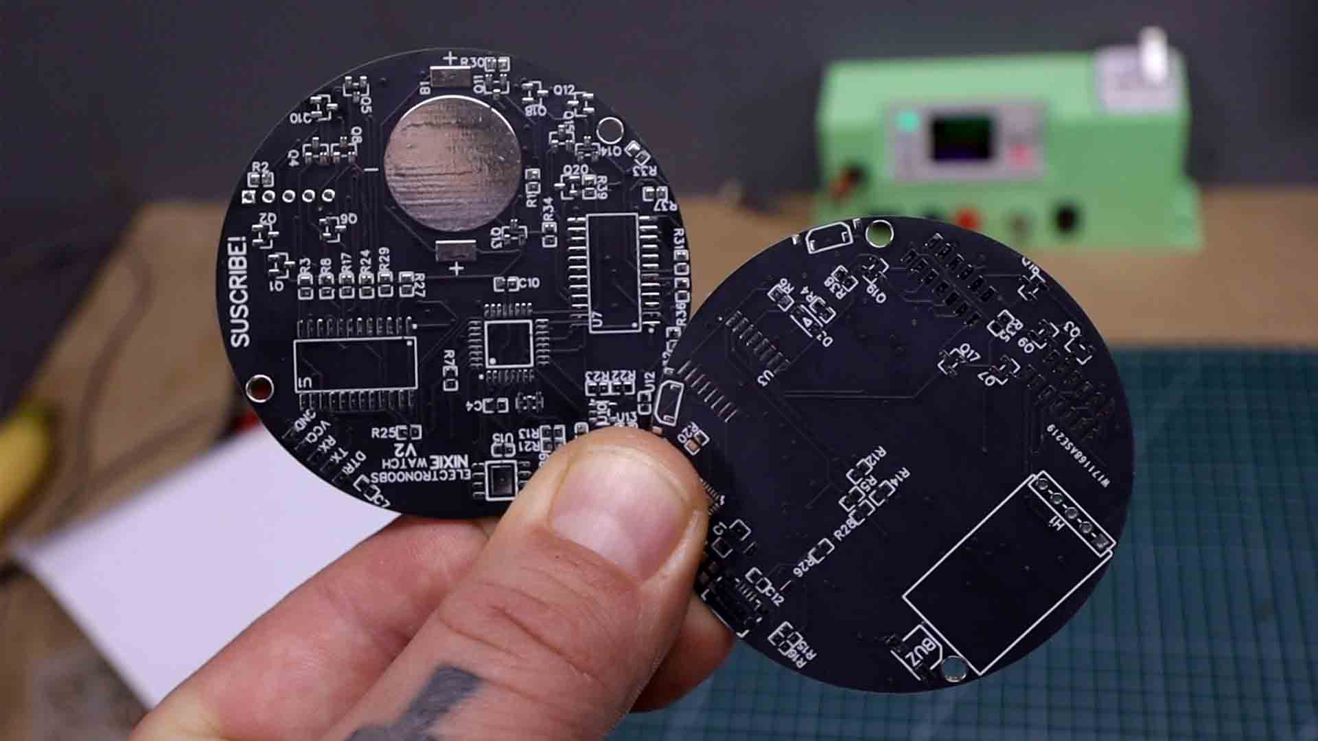
Using Altium designer, the PCB design process is so easy. The crucial update was to replace the drivers with BJTs. But now I have 22 BJTs to control, and the ATMEGA chip does not have enough pins. That’s why I’ve added two MUX drivers using the component list of Altium. I’ve made sure the USB connector is in the correct position so it could be reached. Also, I’ve placed the buttons on the side. In the designer I’ve made the PCB to have 4 layers so it would be easier to route. And to make the routing I’ve used a mix of the Altium’s automatic route and some manual routing as well.
Get my GERBERs files from below and we are ready for the order. Go to PCBWAY.com and click the quote now button. By the way, this project also involves a 3D printed case so maybe also check the CNC and 3D printing services of PCBWay for higher quality 3D parts. Look at the huge list of materials for 3D printing, you have a lot to choose from.Back to our PCB, add the PCB size (62x62mm) and select a color. I want the matte black color because it will give more contrast to the Nixie tubes. Add to cart and on the next page upload the GERBER files and make the order. In just a few days I received my awesome PCBs. PWBWay did a perfect job, they look awesome.
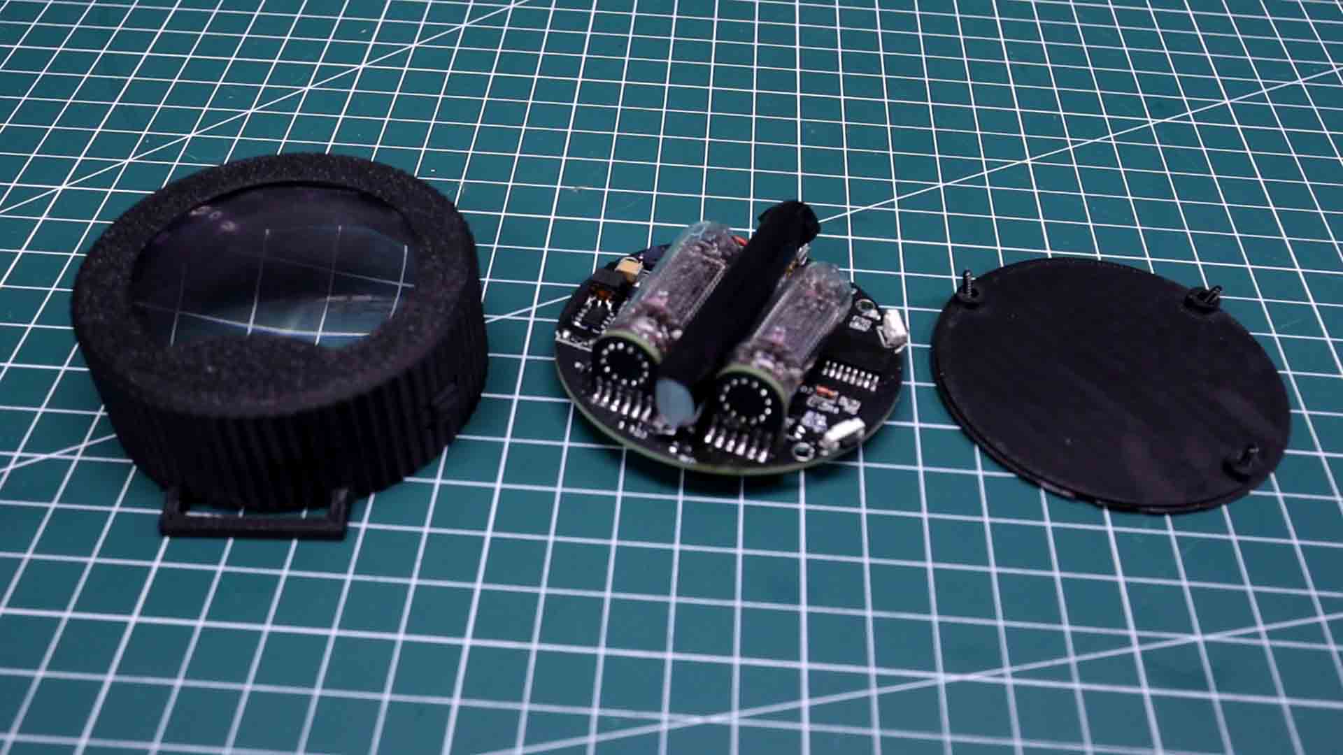
The case is very simple made out of 2 parts. The main case where the PCB will go and the back lid that will be closed with some small 1mm screws. The glass of the case is actually made out of a Fresnell plastic lens sheet so it will look cooler and also make the tubes look bigger. It was printed with black charcol color PLA using my bambulab printer. Some supports are needed for the push button area. The case has two hooks for a simple watch belt.
The code is not that complicated and you can download it for free from below! I’m using digital writing to control 8 inputs of the two MUXes in order to display numbers from 0 to 9. I can also control a green LED that was soldered below the tubes, for some cool effects. I’m using the RTC library for the hour and a minute. I have a mode where I can set the new time and since the RTC chip has an alarm pin connected to the Arduino, I'm planning to add an alarm function as well in the future.
The watch is a bit bulky but that could be fixed with an improved design and eliminating the space between PCB and the tubes. But hey, is a vintage design and vintage stuff is bulky. There is something unique about this build. In an era of high-definition digital screens, this device relies on raw physics. It is warm, complex, and represents a piece of history that glows every time the time is checked. 150 volts and 70 years of history, all contained in one functional timepiece but with extra new technology. All the schematics, component lists, and design files are shared on this post for free. Stay curious, and always prioritize safety when working with high-voltage electronics.