If you want to see how this circuit works, the other circuits we have for this, the use of a flyback transformer and more examples, check this post. I will show you everything you need to know about this circuit, then we assemble it on a prototyping PCB for one circuit and on a PCB kit for the other circuit and make some tests in order to see which one will get best results with music plasma arcs. So, let’s get started.
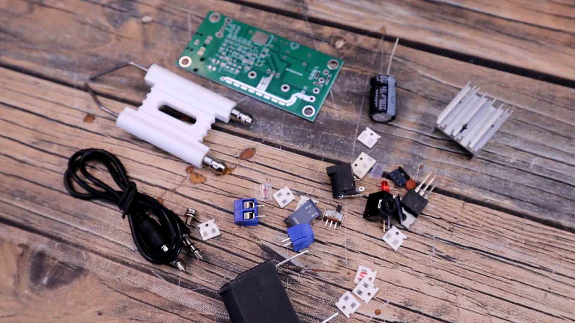
With this kit from the internet, you receive the PCB, the flyback transformer, wires and all the components and following the schematic you can assemble the module. Once assembled, you can connect a 3.5mm jack for music, supply the module at 12V from a powerful supply with around 5 amps of current, and then connect the flyback transformer at the output. For the transformer, to make the primary we need to make between 6 and 8 loops with a thick wire around the ferrite core. Then we connect it to the module and the secondary output will be between the main thick wire and one of the pins below which in my case is marked with a red line.
I supply the module and connect the secondary output to this ceramic support with two electrodes. Ceramic is a good insulator so the sparks will jump only at the tip of the electrodes where the distance is smaller. So follow the schematic and mount the PCB. I add the audio input jack connector, the switch, the MOSFET, which by the way, it must have a heat dissipator otherwise it will burn out very fast, the capacitors and all the small SMD components on the back. Check all the links for this circuit and the PCB below. Is quite amazing to see the plasma arca forming and hearing the music getting out of them.
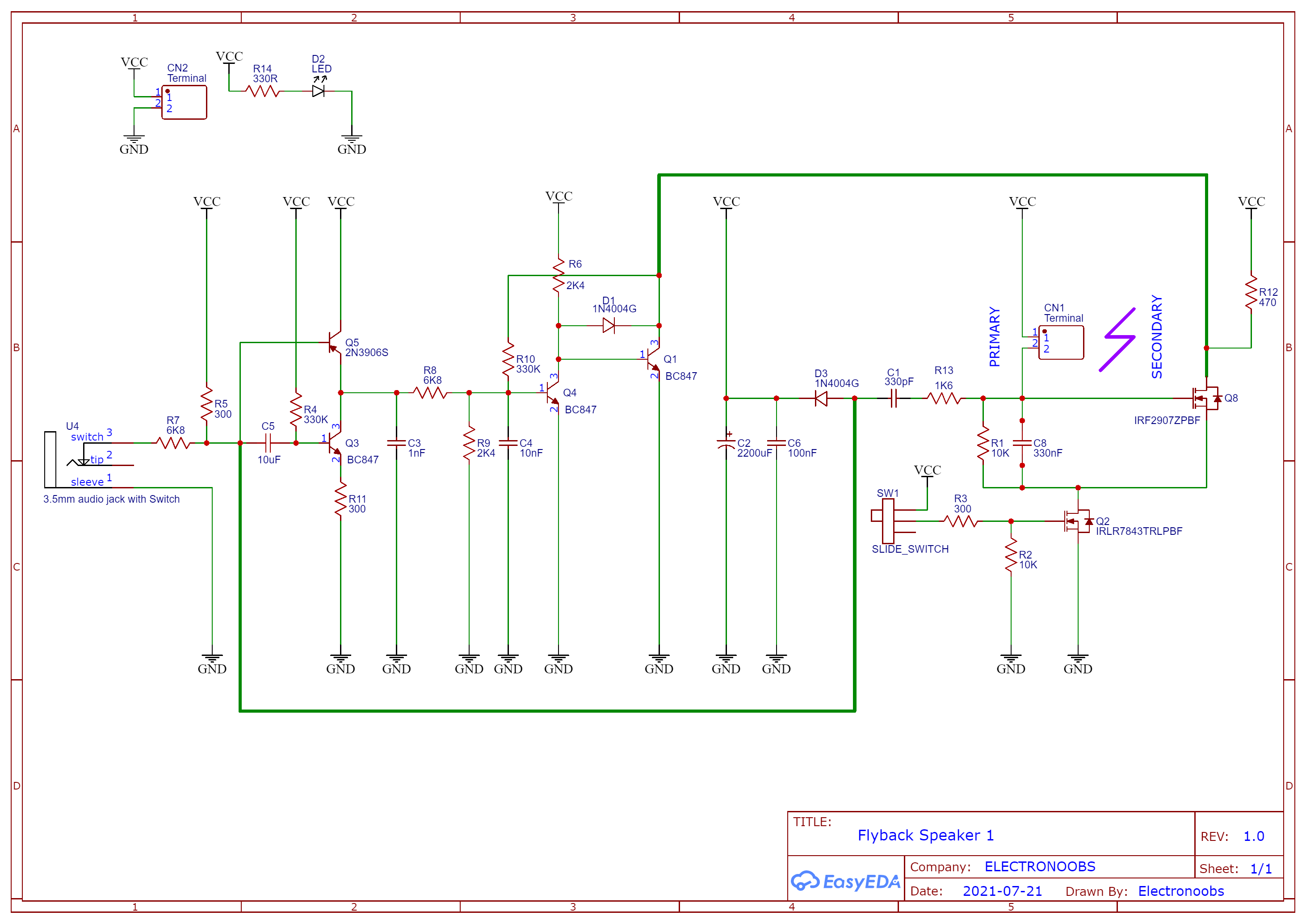
I power it on and apply music from my smartphone. To start the plasma arc you must flip the small switch to off and then back to on, and the circuit will start oscillate and create plasma. The results are quite awesome, we can create arcs of a few cm. The music is not that laud and we can also hear the high frequency hiss of the arcs instead of the actual music. The magic is created between the primary coil of the flyback and the high voltage capacitor. A coil together with a capacitor is a so called LC tank and this will resonate.
The coil is connected on one side to positive 12V. The other side is connected to a MOSFET which is connected to GND through a second MOSFET. So by modulating the signal applied to the MOSFET gate, we modulate when the circuit is closed and power applied to the flyback coil. Music signal is also connected to the base of a two BJT transistors that create an inverter. Then we connect the output to some other BJT transistors in cascade and with that we amplify that signal, because the music voltage from a smartphone if very, very, low. That output is used to apply pulses at the LC tank and make it resonate. On top of the resonance frequency which is given by the used components such as the 330nF capacitor and the inductance of the primary coil from the flyback, on top of that, we insert the music signal as well and that’s how we get the music on top of the plasma arcs. The second MOSFET is connected to GND and is activated with the sliding switch, and that turns the oscillation on and off. Is a pretty easy circuit.
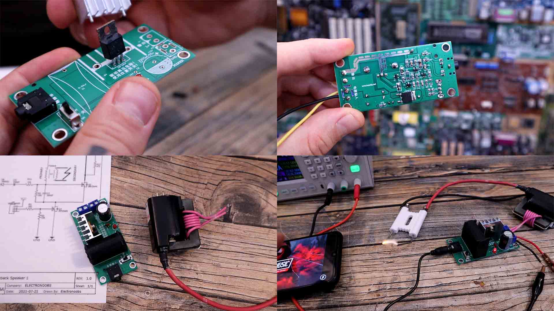
Let’s take a look at the second schematic and this homemade prototype PCB that I’ve made. This circuit is inspired by Franzoli Electronics work. First of all, as you can see I’m now using a huge IGBT and I’ve place it over a big heat dissipator. At such power, the transistor was getting hot in a couple of seconds, very hot, probably more than 100 degrees. We have again a big capacitor of 330nF to oscillate together with the primary coil of the flyback transformer. The main difference for this circuit, is that the music modulation is made with a 555 timer. As you know, this IC will create a square wave and we can change the frequency of that signal using this potentiometer. On top of that, we connect the audio signal to a BJT transistor to invert it and then we control the reset pin of the 555 time, and by that we tell the IC when to enable the high frequency output or not. By that, the output signal will be with the rhythm of the music. The rest of the circuit is just a regulation IC to get 12V from 24V because this circuit works at 24V but we supply the 555 timer with only 12V.
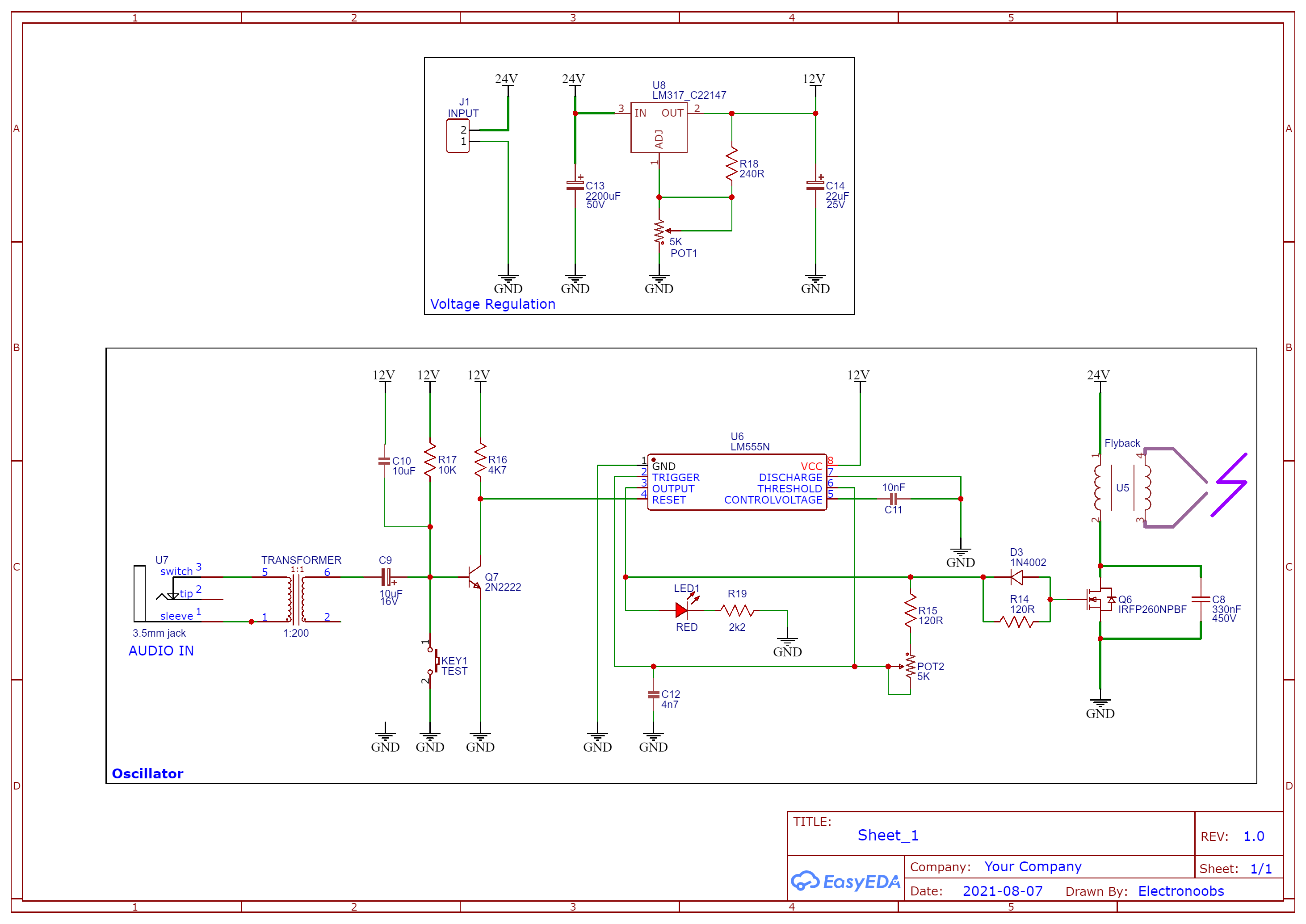
Again, the flyback primary coil is connected between VCC and a MOSFET connected to ground, and the gate of this MOSFET, which in my case is an IGBT, is controller with the square wave from the 555 timer. Between the drain and source of the transistor we have the 330nF capacitor and that’s it. I first solder the voltage regulation part with a huge capacitor at the input, since this circuit will create a lot of noise. With the multimeter and the potentiometer, I set the output at 12V. Then I solder the rest of the components and I place the IGBT external to the PCB and fix in place on the heat dissipator, this is very important since the circuit will waste a lot of power and transform that into heat.
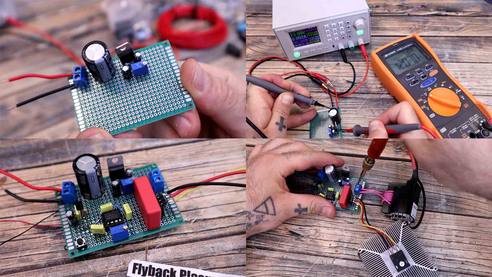
I connect the flyback at the output and the secondary is connected on one side to a metal case to increase the area and on the other side just a simple wire. We supply this at 24V and make sure your supply could give out 5 or 6 amps, otherwise the voltage will drop. This circuit needs more than just a few mV at the base of this transistor in order to control it with the music. Since the music signal from the smartphone is very low, we need to amplify that signal. Franzoli electronics has a circuit for that with an operational amplifier but that didn’t quite work form me, maybe I had some connections errors. That’s why for this test I will increase the audio signal using another high voltage transformer that I have laying around. The output from this transformer is connected to the audio input of my circuit and now we can test it. I play some music and power on the circuit and there you go.
We can get huge arcs, of a few cm and that’s amazing. The music is louder and the sparks are powerful. The circuit is using around 150W. The IGBT is getting quite hot. If we make the gap to big, the spark will die and new sparks will appear at the base of the flyback transformer so watch out with that because we could damage the transformer. So guys these were my tests for a plasma speaker and a so called interrupted plasma speaker. The results are sparky and awesome, right?
I hope you like this tutorial and maybe you have learned something new. If my videos help you, consider supporting my work on my PATREON or a donation on my PayPal. Thanks again and see you later guys.