 @kaltronik
1 month ago
@kaltronik
1 month ago
parabens
No more power adapter cables or heavy soldering station cases. This iron weighs only 81 grams and it could reach 450 degrees, which is more than enough for me and is all thanks to this.
by: ELECTRONOOBS on 2026-05-26
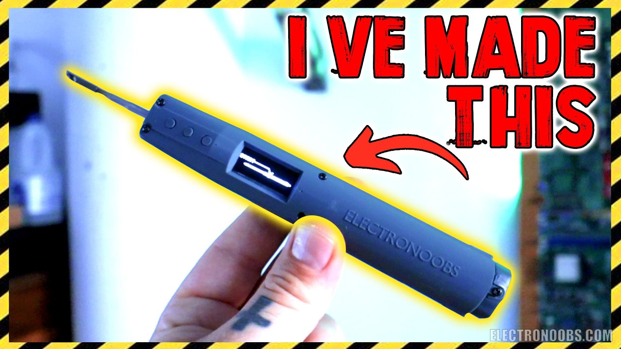
Finally! I finally did it. A fully portable soldering iron with internal battery. No more power adapter cables or heavy soldering station cases. This iron weighs only 81 grams and it could reach 450 degrees, which is more than enough for me and is all thanks to this. This is the tip I’ve used for my design and is all I’ve been searching for a long time. Now that I have it, let me show you how I've designed such a soldering iron, the PCB we need for it and all the components and show you how to make one. It gets interesting so stay till the end and your interaction with the video gets this kind of projects going and me sharing them for free on my website as always. So thanks for your likes, comments or watch time. That being said, let’s get started. If you also want PCBs, use the services of PCBWAY.com and order professional boards for only 5 dollars!
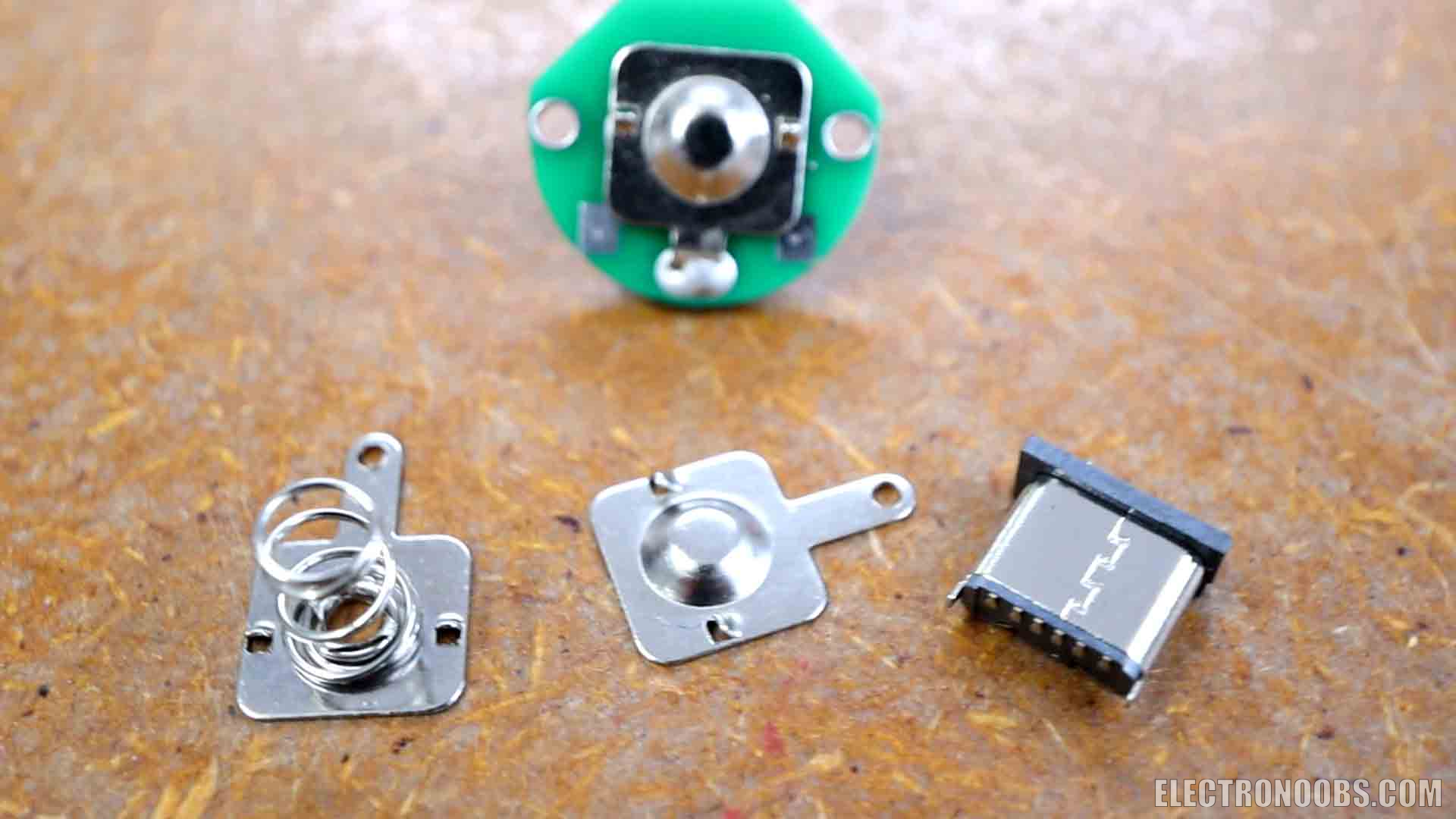
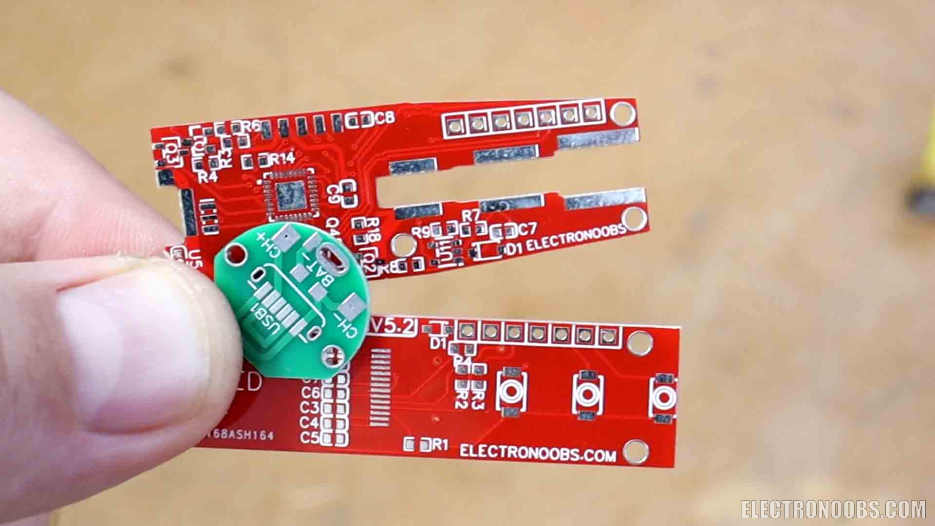
Obviouslly you need my PCBs so download the GERBERs and orther them at PCBWAYT.com. To get the sensor smaller PCBs just snap them with your hand and like that you will have 3 PCBs at the price of just 1. On the main PCB we have the ATmega328 chip for the main microcontroller, and the L6234PD for the motor driver. The PCB has extra stuff such as a buzzer for sound notifications, a MOSFET and a fan output to cool down the components and two inputs for a potentiometer or i2c control. Check the full list below.
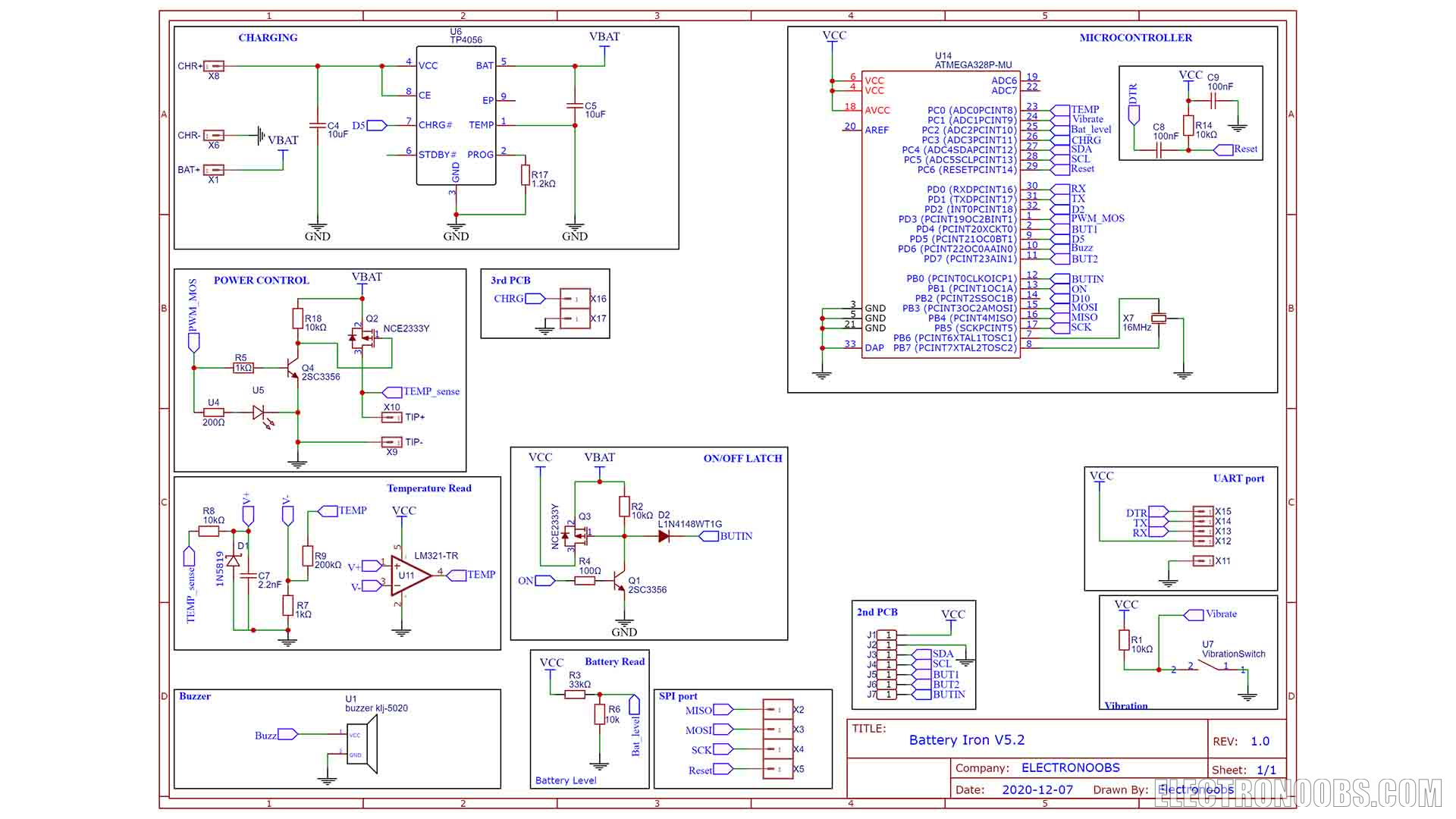
2.1 Check the schematic below for the controller PCB
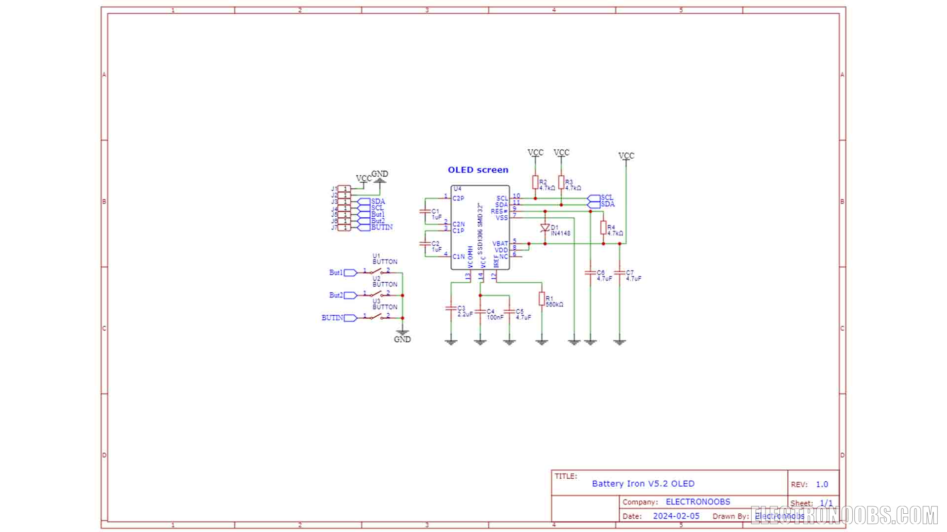
2.2 Check the schematic below for the display PCB
2.3 Check the schematic below for the battery connector PCB
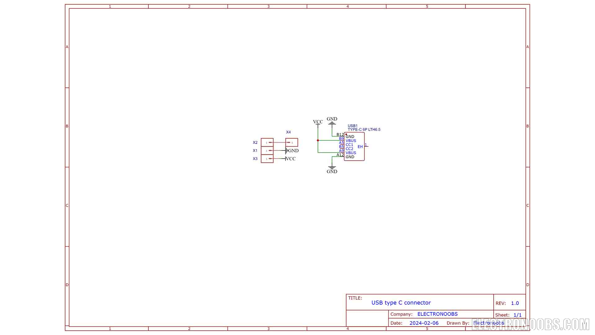
First of all, my new design of the PCB. Actually PCBs, because we need 3 of them. The controller PCB, the PCB for the OLED screen and a smaller PCB for the USB input for the battery charger. If you want to make this awesome project and challenge yourself you can download my GERBERs for the PCB from below. As always I’ve used the services of PCBWAY to create these awesome boards. Once you have my files, go to PCBWAY.com and click the quote now button. Here select your settings. I leave all by default and I set the color to red. On the next page upload the GERBERs and make the payment and in just a few days I received my PCBs. This design turned out awesome, is small and with a weird shape and let me tell you why. or you could get them from my shop and support me: LINK HERE
Part 4 - 3D Case
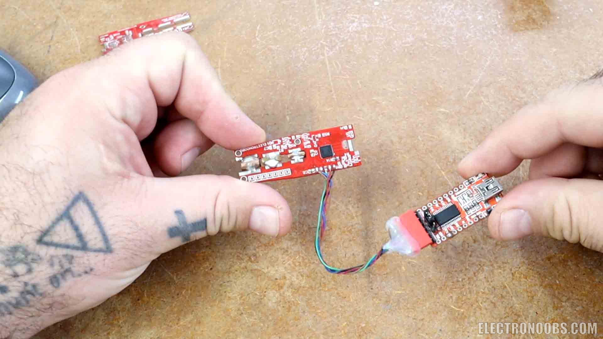
To keep the barter, the PCBs and the USB connector together I need to design a case. This is the design. I’ve made more than 6 versions till I got something that is small, compact and looks good and I will make it better for sure in the future. I 3D print the case using my resin printer. It has a hole for the USB connector so we add that with two wires for battery negative and charging VCC. Now I take the controller board with the display and make sure it has the positive spring for the battery. As you can see the case has pins so the PCB will fit perfectly. With the PCB in palace test if you can add the battery. If yes, we can solder the wires from the connector to the main PCB. To close the case we use the other 3D printed part as a cover. We can use small screws and close the case and that’s it but before we assemble it we upload the final code which you could download from below. And there you have it.
The first thing to do is to start heating the tip and write down the analog read from the thermocouple and the real temperature with a thermometer. I take a note each 20 degrees or so and I create this graph. With these values I can calculate the formula of passing from analog read to real temperature in degrees and use it in the code here. This function reads the ADC and passes the values to temperature. In the code, using the temperature, I also make a PID code that will control the PWM signal that goes to the power MOSFET. Like that we can control the heating process and keep a steady temperature. Very important, we need to turn off the power mosfet before each temperature reading. The thermocouple is in series with the heating element of the tip, so we can’t measure it while powering the heater. That’s why here in the code I place the MOSFET to low, add a small delay, and then read the temperature.
A fully portable soldering iron. It has sleep mode so it will turn off when not used, minimizing the battery use since we don’t have much. Also, it only uses a lot of power when heating up and when in use. For keeping a steady temperature, the power use is low. As you remember from the previous version, we use PWM signals to control the power and for just keeping up the temperature, the PID output is minimal. Here is a speed test and it reaches 300 degrees in around 15 seconds which is not bad and we could make it faster by making the PID code more aggressive but with that, it might overshoot. Is also quite precise, I set it to different temperatures and it keeps the values that setpoint with no problems so the PID works. We can use the other two buttons to adjust settings for temperature, sleep mode time, screen rotation and so on. I’m quite satisfied with the results. Thanks again and see you later guys.
@kaltronik
1 month ago


Leave a comment
Please login in order to comment.