This is by far the best way to control your livestreams, any professional streamer uses something like this. This is a so-called STREAM DECK. But this one is homemade and personalized with an Arduino MICRO, a TFT display, push buttons, some RGB LEDs and the Keyboard library from Arduino.
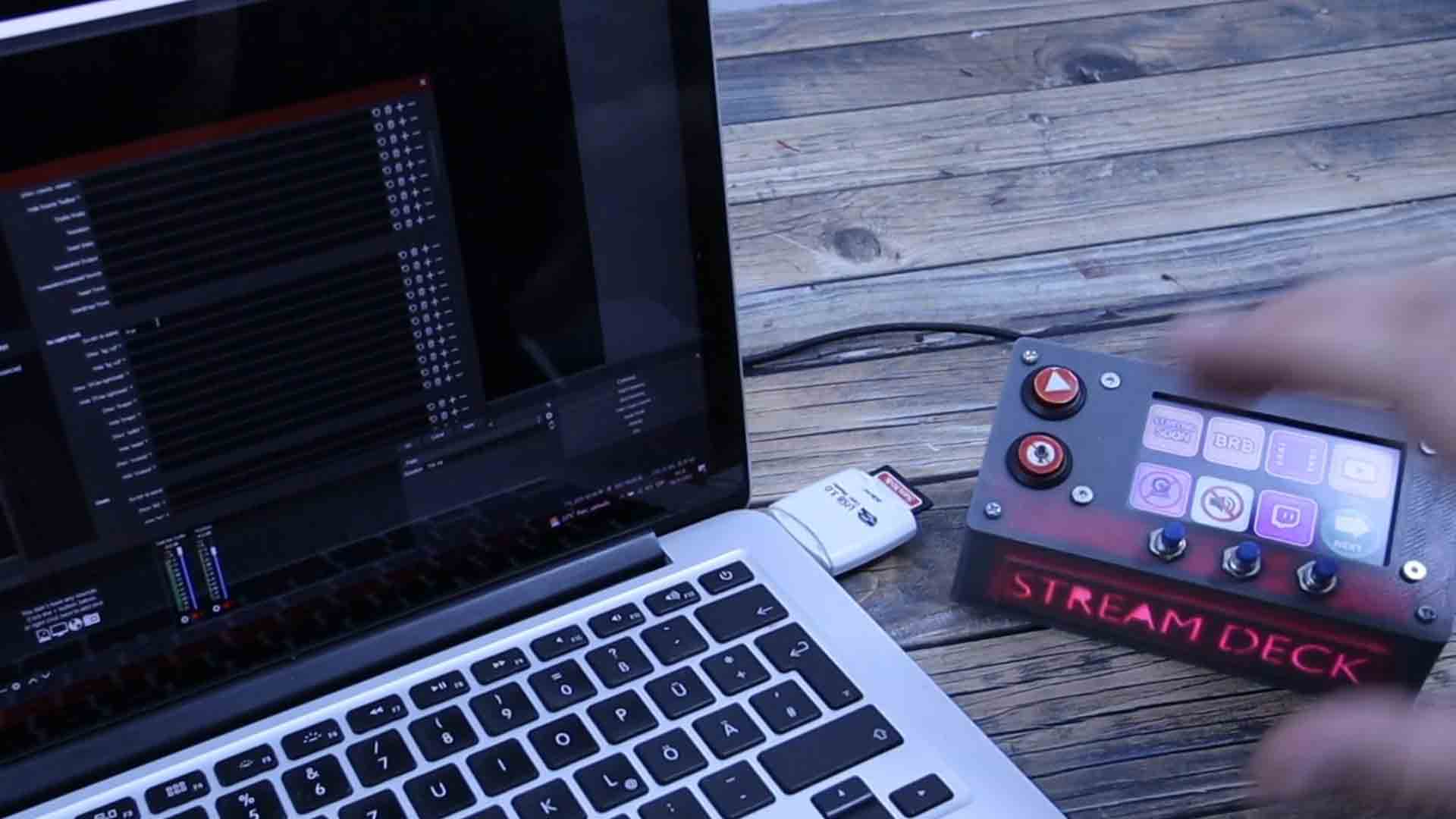
You can use this with any streaming software such as twitch, OBS studio, X split and so on. Just press a button, and you could change the scene, disable the microphone or the webcam, add music to your livestream, change to “be right back” and so on, anything that you want. The deck has 7 buttons on the display but if you press the next button you can change to a different template with 7 more buttons. On the side we have two more real push button and 3 more below the display. To give it a cooler look, I’ve also placed some RGB leds inside and made them fade rainbow colors. In the code you can change which key you want to send to the PC and for the connection, it uses a USB cable so you could connect it to any device. Let me show you what you need, give you the Arduino code, the TFT file for the display and the 3D files for the case so you could make your own. So guys, let’s get started.
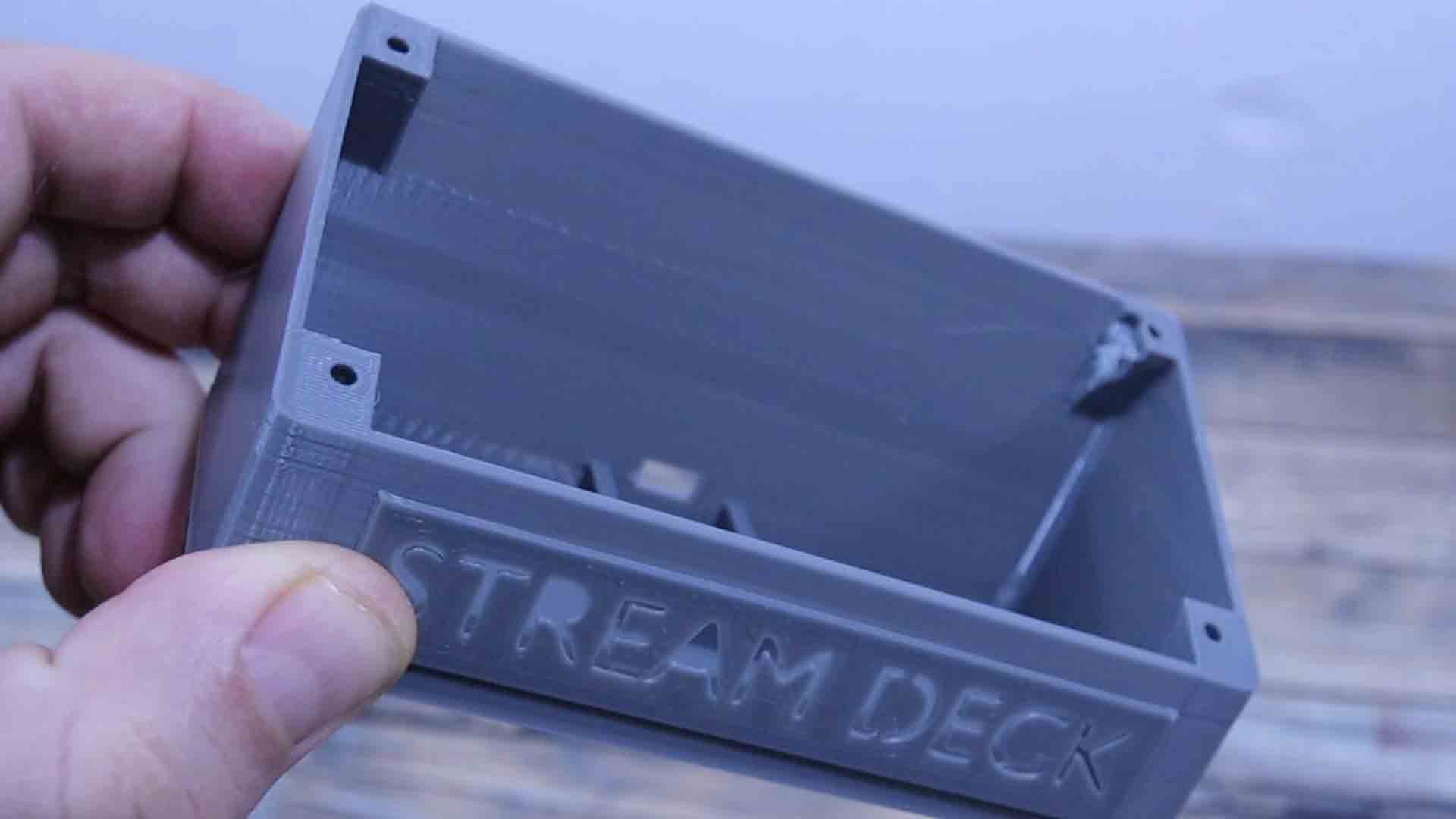
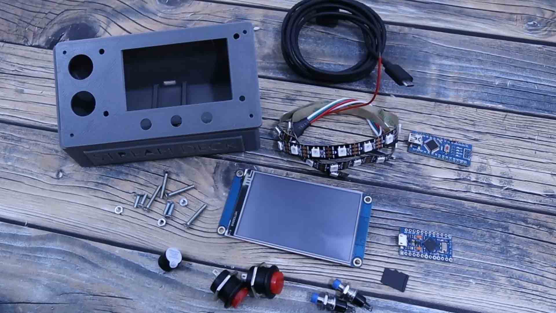
To make this project we need a few components starting with an Arduino MICRO. It can’t be the Arduino UNO or the NANO because the Keyboard library is compatible with the Arduino MICRO or Leonardo which are using the ATmega32 U4 microcontroller. Together with that we also need a Nextion display. In my case I’ll be using their 3.2 inches model. Together with the display I will also add 2 real push buttons like these ones and 3 more buttons. I also want to add RGB colors to the deck so I will use the addressable LED strip together with a separate Arduino NANO. I don’t want to overload the Arduino MICRO too much so a separate Arduino will be in charge of the RGB colors. We also need some M3 screws and nuts together with the 3D design I’ve made for this project. You can download my STL files from below and print them up. I’ve used 2 perimeters, 30% infill and PLA material. We need the main case and the cover together with the logo part. I’ve printed that part separately so I could print it with this face downwards. I will also add a buzzer for sounds clicks. Together with a micro SD card and a USB cable for the Arduino, this is all we need to make this project.
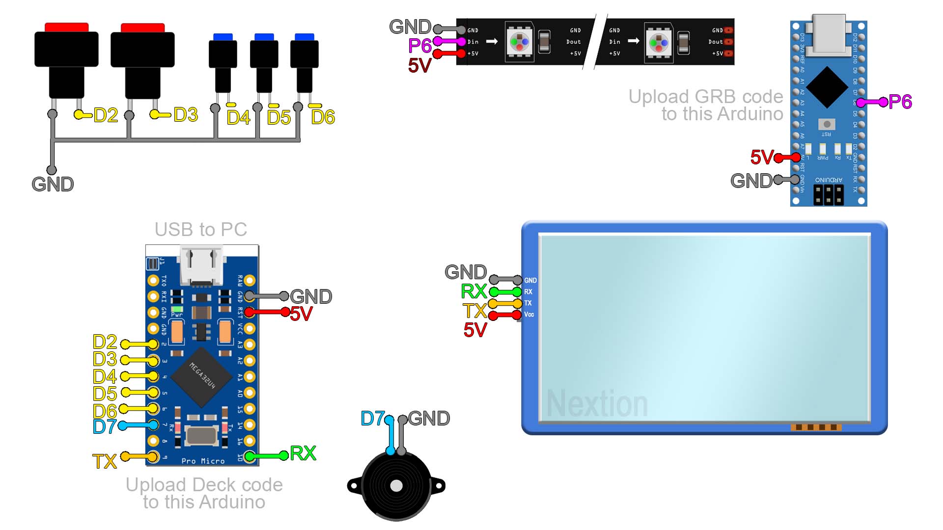
The schematic is quite easy. Follow the connections as below but first have in mind we have to upload the TFT file to the display so check the next chapter. Anyway, the connections are easy, the UART pins from the display connected to the Arduino and a few push buttons with GND connection and a digital pin of the Arduino as well. Power is supplied from the USB cable and we need to share 5V and GND with the second Arduino for the RGB colors. That's it.
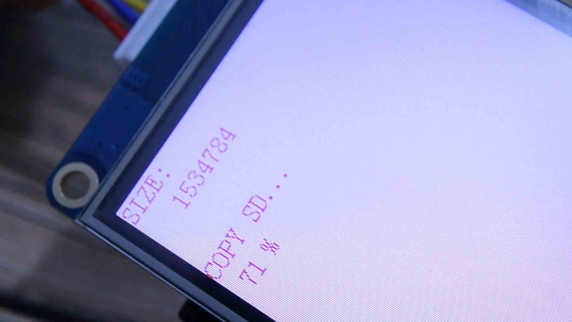
So first, let’s prepare the TFT display, so get the screen and a micro SD card formatted as FAT32. Download from below the TFT file in a .ZIP format and extract that file. Then, copy the file to the empty SD card. Insert the card into the Nextion display. Then power it up and you will see how the new TFT file is uploaded to the screen. When you get 100% completed, power off the screen. Remove the SD card and power back the display and you will get my design. As you will see we have 7 button on this page and if you click next, you get a different design. Actually, like this you could add as many pages as you want. Check my Nextion Editor video and you will see how easy is to create a TFT file for this type of display. In the Nextion platform, each button will send a different number from 0 to 13. And later we read that with the Arduino.
You can download my STL files from below the video and print them up. I’ve used 2 perimeters, 30% infill and PLA material. We need the main case and the cover together with the logo part. I’ve printed this part separately so I could print it with this face downwards.
Now we have the screen so having in mind that the connection schematic for the project it on the above chapter, let’s start assembling everything. I add the screen to the cover 3D printed part using M3 screws and nuts.
Then I’ve printed some icons with my printer on white paper. I glue those to the big buttons. On top I add a clear coat of transparent nail polish. Just like that we have some personalized buttons.
I add the big buttons to the cover as well. Then I also screw in place the small push buttons. I solder wires to all buttons as in the schematic. The Arduino MICRO will later go here inside the case. Make sure you can connect the USB cable. Finally, solder all the wires to the Arduino. From the screen, from the push buttons and for the buzzer. Now the Arduino MICRO has all the connections and two wires for 5V and ground to supply the other Arduino.
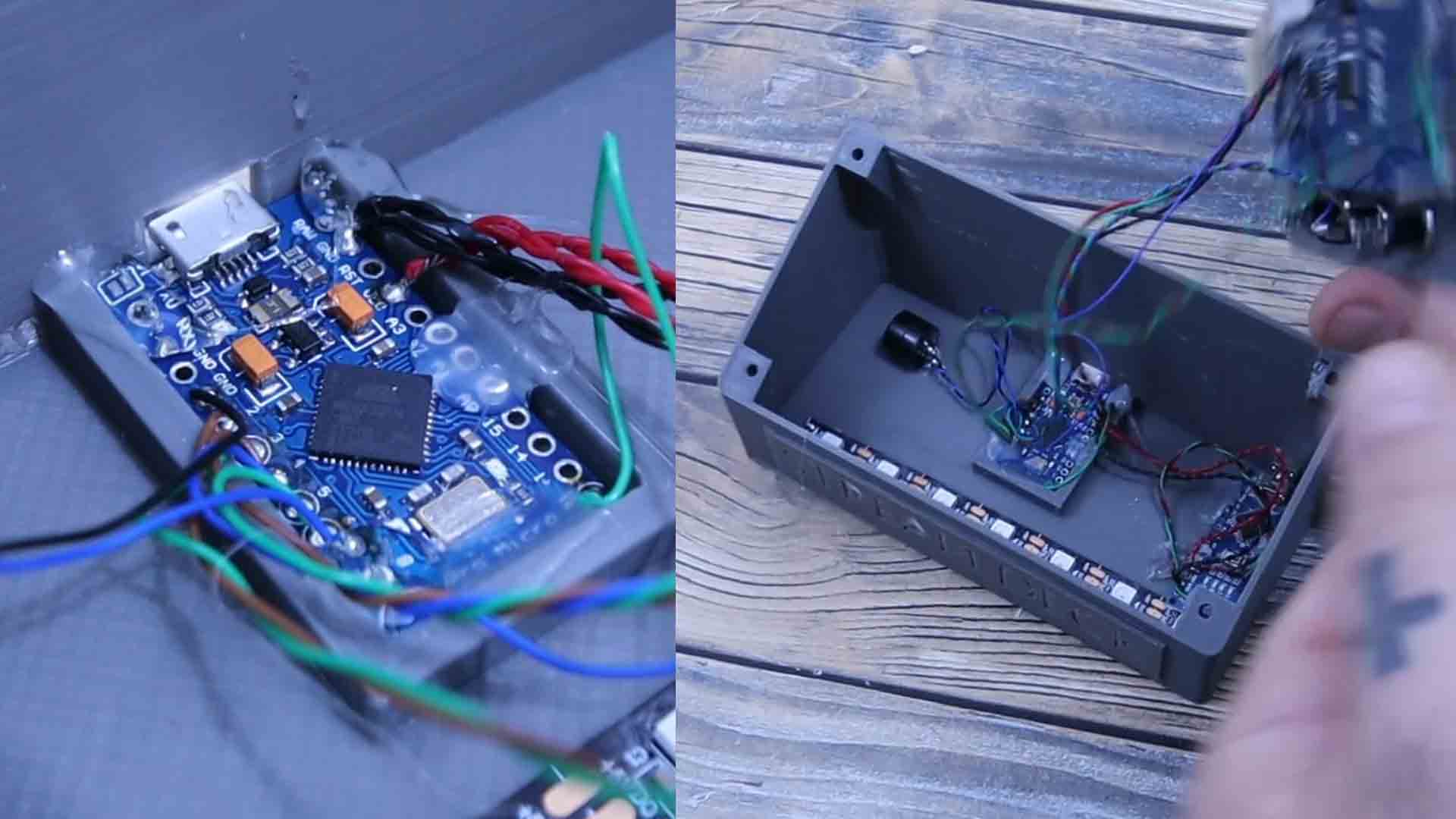
On the other side I prepare the Arduino NANO with the RGB strip. I only use 7 LEDs so connect them to the Arduino 5V pin, ground and a digital pin. Then we upload the second code that will create the rainbow colors as you will see.
First we import the Keyboard library. This will mimic a real keyboard and send different keys using the function press, release or write. A normal PC keyboard could have the keys from F1 up to F12 usually. But virtually we have keys up to F24 and we could also use those. We do that so we won’t interfere with any other key. So in the Arduino code I create a serial communication with the Nextion Display. When I receive a 0, meaning that the first button was pressed, I will send through the USB connection the F13 key using the keyboard library. I do the same for the other numbers. Also, when I detect that one of the real push buttons was pressed, I also send a different key from F20 to F24. That's it.
/Keyboard.begin();                 // Initialise keyboard control
int Received = mySerial.read();      //Save the received String in the Received variable
    if(Received == 0)                   //If the first character of "Received" is "1"
    {
      Keyboard.write(KEY_F13);                  //We type this keyboard
      tone(buzzer, freq, tone_duration);
      delay(100);
    }
By the way, for me the basic Arduino MICRO board didn’t work to upload the code. The PC would not recognize the board anymore. Use the guide on my website on how to install the sparkfun pro MICRO boards and how to burn the sparkfun bootloader in case that you have the same problem.
Once you do that, select the Pro MICRO board from the boards tab. Then compile and upload the code. Now we have a working stream deck and each button will send a different key to the PC.
With the stream deck connected to your PC, open your streaming platform. In my case I will test it with OBS. I go to settings and then to hotkeys. You could palace hotkeys for anything. Look, when I press any button on the stream deck, a different keys appears on my PC. For example I place a key to change to the “be right back” scene. Another key for the gameplay scene and so on. Use them however you want.
If my videos help you, consider supporting my work on my PATREON or a donation on my PayPal. Thanks again and see you later guys.