The PCB on this project is called "NOOBIX" and gives you full IOT control for anything. A lamp, a fan, your stereo speakers, your printer, anything you want. With a simple online push of a button from anywhere in the world, you can turn ON or OFF any device that works at 220V AC. This project is based on a previous tutorial where I show you how to use the ESP32 and the HTTP library in Arduino IDE. The PCB has its own voltage regulator from 220V AC to 12V, 5V and 3.3V DC, it has a solid state relay to control 220V AC and 2 amps of current, it has pads for a very small ESP32 and it has the main input and output. Is very easy to use so in the video let me show you how to create an IOT control using this PCB and control any device around your house from anywhere in the world with internet connection. By the way, in the future we might make this PCB also work with Alexa so stay tuned for that. So, guys, let’s get started.
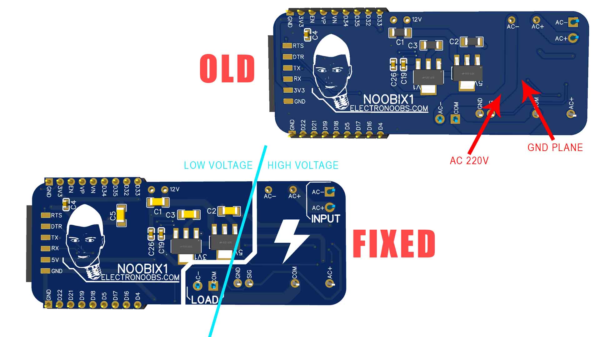
● Some of you guys on the community commented that the AC high voltage clearance is too low. YES, YOU ARE RIGHT! I usuall add copper plane to all my PCBs and that was a mistake made ina hurry. So even if you see a bad clearance in the video, the final PCB you can download from below, has all the errors fixed with enough clearance. For a 1.6mm thick OPCB, the recomended clearance on the same layer for 220VAC is 2.5mm or above. Now all the high voltage is separated on one side with decent clearance.
● Other mentioned parts were about the connectors that they can't handle more than 150V and 6A. Actuall, the connectors I've used were rated for 300VAC and 10A but maybe the supplier is a liar so I can't know for sure. Also, the maximum current I say in the vidoe thos PCB is rated for is 2A. That's because the SSR could only handle that so we would never get to above 6A. If you do that, is your mistake!
● You also mentioned that the exposed tracks and pads are dangerous to handle! Whaaaaat? Why would you handle such a PCB while connected to voltage? To use such PCB, you should first cut off power from your entire house by lowering the safety switches. Then connect the PCB to power and load. Then place the PCB inside of an insulated plastic case. And then you turn the power back ON. You should never touch the exposed PCB, are you crazy? I say that in the video. A lot of other commercial IOT PCBs have exposed pads/trackas but you should never touch them!
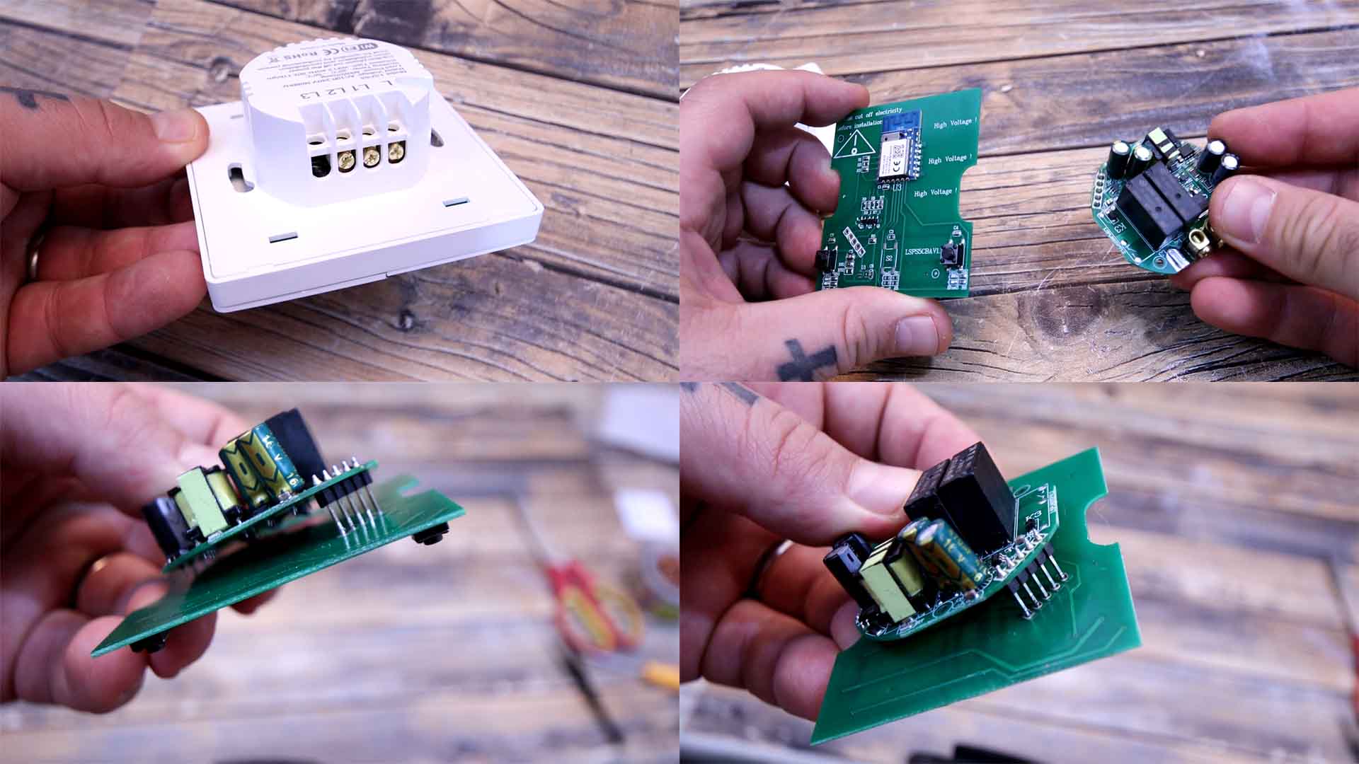
● Another thing that was mentioned was the voltage regulator module. The module is ok because it has an insulated connection through a transformer so that’s not a problem. But yes, the module has high voltage and is soldered a bit too close to the PCB (actually it has around 2mm of clearance which sould be ok). For that we have two options: Add a plastic separator in between the module and the PCB, or maybe just solder the module in mid-air. For example this below is an IOT board that I bought and works with Alexa (is a commercial PCB). This has the regulator module here and the IOT circuit on the other side on another PCB. They are merge together with some pins of a few mm to add insulation. I could do the same with my PCB and like that we have enough clearance. So, problem solved.
So for those who are exaggerating and saying that this will kill people and insulting me!!! Please tell me how? The only way to kill someone here is if you touch the PCB while powered on. And you should never do that. And that applies to so many other PCBs. You should never touch a powered relay, it has exposed pads. Never touch a power supply neither. Never touch a converter and so on. These are all dangerous to touch if powered on.
The only thing I could imagine that could happen before I’ve fixed the clearance, is that the high voltage could have jumped to the low voltage blowing up your microcontroller. And since the tracks are 0.22mm they would acts as fuse and just burn out. So my only concern was related to fire and not being electrocuted.
But even so, if you were right there are ways to tell me that. That’s why I want to talk about constructive comments. If you see an error in my videos, you don’t have to call me names. You can just say which is the error and if you can, you could even say a solution to that error. That’s constructive and it will improve the project and help the community. Saying that I’m a s***id f**k and should delete my channel, is not constructive!!
What’s up my friends, welcome back. This below is the PCB that I’ve designed for my project. I’ve tried to make it as small as I could so it could fit inside of a basic wall electric box.
Since it works at 220V AC and the ESP32 needs 3 to 5V DC, I’m using a voltage converter module. That is very small and will give us a very steady 12V DC and 1 amp of current which is more than enough. Then, on the other side I’m using two linear regulators to get 5V and 3.3V. The ESP32 is controlling an SSR or solid-state relay. And that relay is connected to the output where we can connect our load. I’ve placed some pins around in case that you want to connect anything else to the ESP32. So guys go and download the GERBER files for the PCB from below. Then go to PCBWAY.COM and click the quote button. Add the size of the PCB (71 x 30mm), the amount of boards that you want and select a color. Since the green one is made faster, I selected the green solder mask. Save to cart and on the next page click the upload button. Now upload the GERBER files you’ve just downloaded from below my video. Make the order and receive my PCB in just a few days. Give them a quick inspection, but as always they look great.
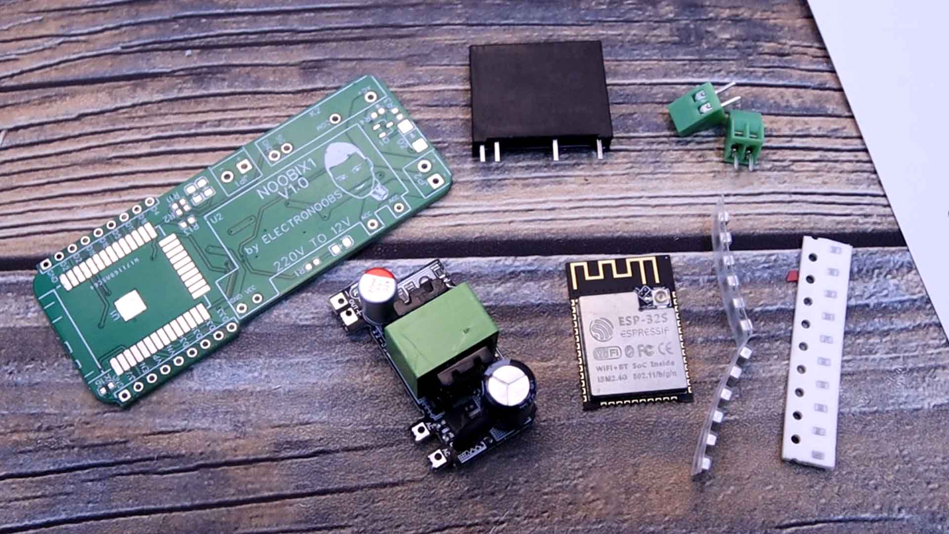
Let's see all the needed parts and also check the schematic for this project below in order to know where to connect each part. We need the 220V to 12V regulator, the solid-state relay, an ESP32S smd version, some SMD capacitors and resistors, a diode, a small BJT transistor, some LEDs as well and the input and output screw terminals. This animation above should be the finished PCB Later we will see how to connect the PCB to mains input and the 220V AC load.
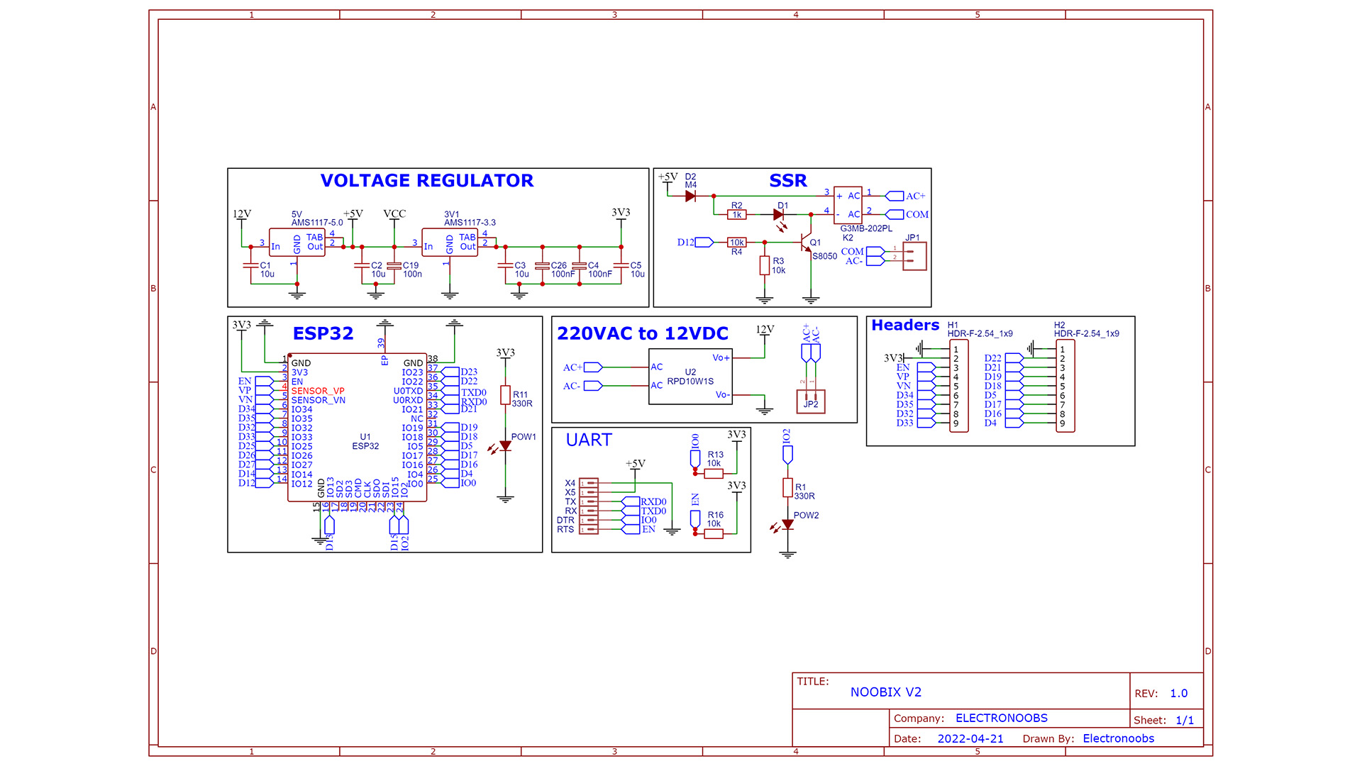
The schematic is quite easy. The basic configuration of the ESP32 chip with pullups to 3.3V for Enable and RST pins. The converter module give us 12V so we connect that in series with the AMS1117 regulators of 5 and 3.3V. The Relay circuit is simple. We use a BJT to connect pin 4 of the SSR to GND so we turn it ON. That's how when the D12 pin is HIGH, the NPN is ON so the Relay as well. We also have the UART pads for programming.
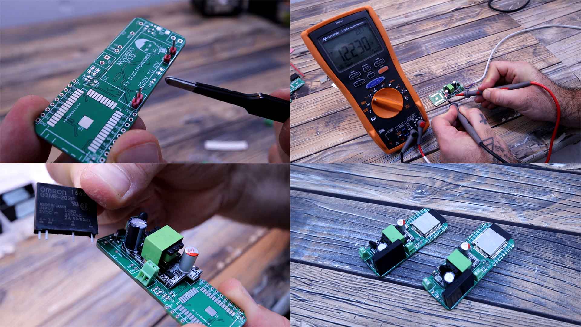
First I solder the voltage converter module. For that add 4 male pins. And on top of those pins we add the converter and we solder it. I also add the input and the output terminals. Then I carefully connect a 220V AC cable at the input. Be careful, and then connect it to power and check the voltage output of the module. If it is around 12V, we can continue. Then I solder the 5V and 3.3V regulators on the back of the PCB. Then I do the same and check the voltage output with my multimeter. Now that we have the voltage regulation part we can add the rest. I solder all the small resistors, capacitors, diodes and LEDs. I add in place the SSR. Finally I solder the ESP32 and the PCB is ready but we need a code uploaded with an external FTDI programmer connected to the UART pads on the back of the PCB.
Please check my previous tutorial about IOT with the ESP32 in order to understand more because I won’t go over those steps again. In the video below you learn how to make the website, the database, the internet connection and so on. Follow the same steps and get a website domain and a hosting service. Create a database and then create a table called LED_status with two columns, one named ID and another named status. Create a new row with ID 1 and status 0.
Then download from below a .zip. Extract that ".zip" and you will get three PHP files together with the CSS file and two images. Open the connection.php file and place your values from your database for the host, name, username and password. Now save this php file and then you must upload all 3 files to your website directory together with the CSS and the pictures. If you go to your website you should now have a button like this one that should toggle the LED status value on the database table from 0 to 1 and from 1 to 0.
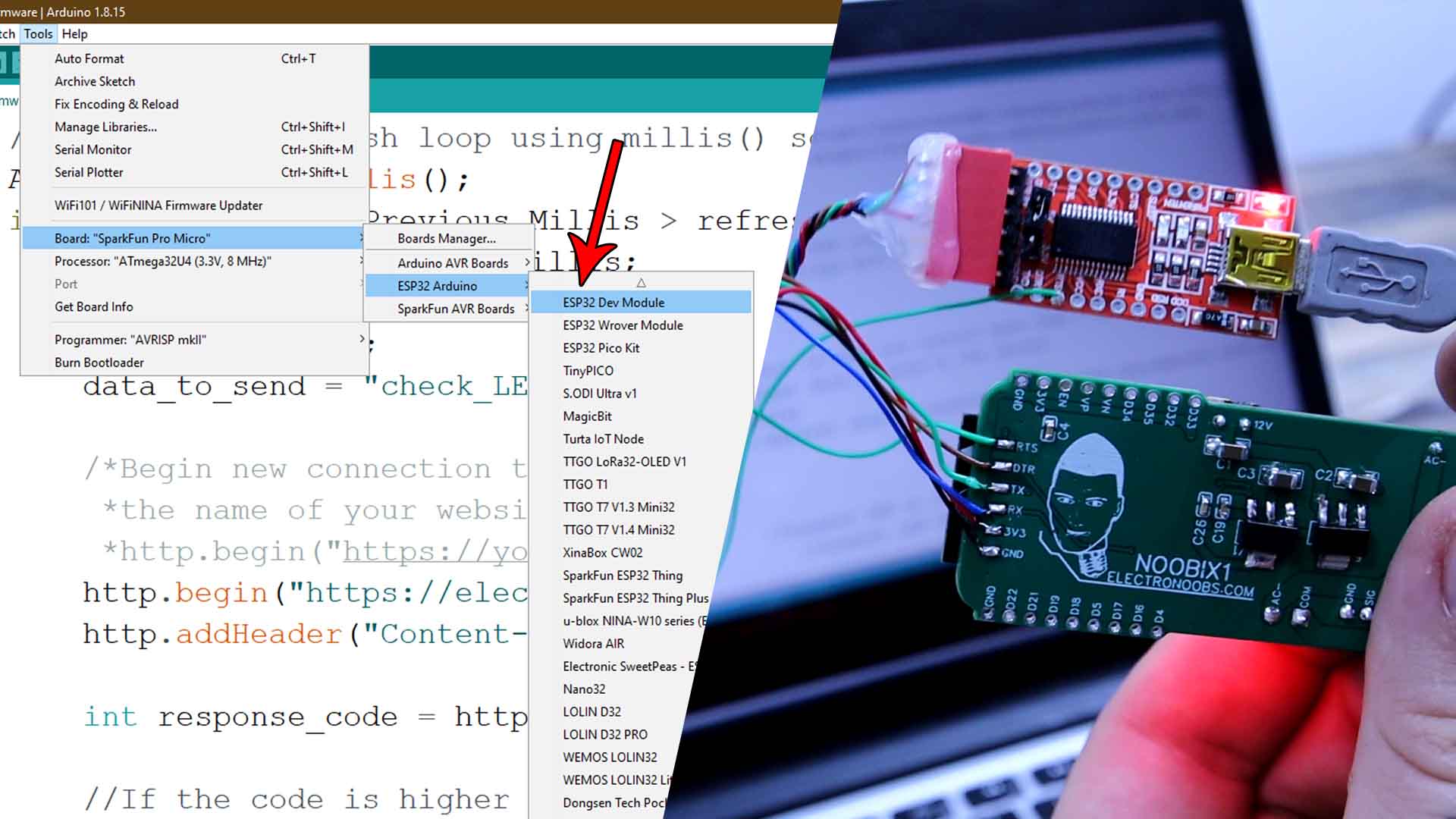
Now download the Arduino Code from below. Read the instructions in the code line by line. First, you have to change your wifi name and password. Then scroll down and in the http.begin function change the website from "electronoobs.com" to the name of your website. See in the previous video how to install the ESP32 boards. Once you do that, go to tools, board and select the ESP DEV MODULE board. Connect wires from an FTDI module to the PCB:
| FTDI | Noobix |
|---|---|
| RX | TX |
| TX | RX |
| DTR | DTR |
| RST | RST |
| GND | GND |
| 5V | 5V |
//Add WIFI data
const char* ssid = "mywifiname";              //Add your WIFI network name
const char* password =  "12345678";           //Add WIFI password

/*Begin new connection to website. Make sure you change "https://electronoobs.com/" to
 *the name of your website. So the next line should be:
 *http.begin("https://yourwebsite.com/NOOBIX_V2/esp32_update.php");*/
http.begin("https://electronoobs.com/NOOBIX_V2/esp32_update.php");          //Indicate the destination webpage
http.addHeader("Content-Type", "application/x-www-form-urlencoded");        //Prepare the header
Now as you can see in the tutorial video, each time I toggle the button on my website, the LED on the NOOBIX board is also turning on and off. But we can also connect it to high voltage. Connect a 220V load at the output. Then we add a cable at the input and connect 220V AC. The board should automatically turn on. Now I go to my website and as you can see, we can toggle the light bulb on and off. And we can do this with any device. And remember that this is not a local connection. This works via the internet so you could control the NOOBIX module from anywhere in the world with a simple internet connection. Now I could add multiple modules and change the web interface with multiple buttons. I give an ID to each one and I could control more than just 1 NOOBIX. So guys get all the files from above and create your own IOT NOOBIX module with my PCB, Arduino code and PHP files. If you know PHP and CSS coding, you could create a better website or even a mobile App so good luck with that, it should be interesting.
If my videos help you, consider supporting my work on my PATREON or a donation on my PayPal. Thanks again and see you later guys.