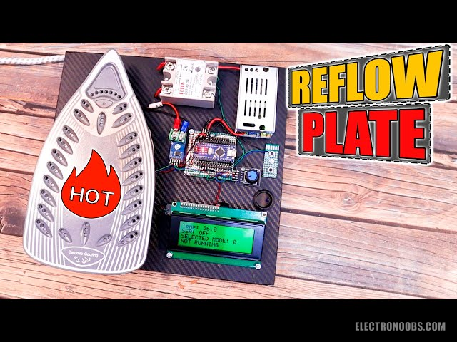
I’m preparing a video where I show you how to make the PCB design and order the panel version for your board and then solder all components at once. In that way you can save time and finish your product faster so they will be ready for sale. To do that I need a reflow hot plate and that’s what we will build today using a second-hand clothes iron.
by: ELECTRONOOBS on 2026-06-20
We need to measure the temperature, show the power and that temperature on a screen so the user could see the values, we need to control power and in this case a lot of power because my iron is of 3000W, and then we need to have some sort of menu or control in order to select the settings. Let me show you what parts we need, the connections I will do, how to measure and control the temperature at high power and also show you the code. Finally, let’s see if this homemade reflow hot plate will work and if I can reach the desired temperature curve, so what do you think, will it work? So, guys, let’s get started.
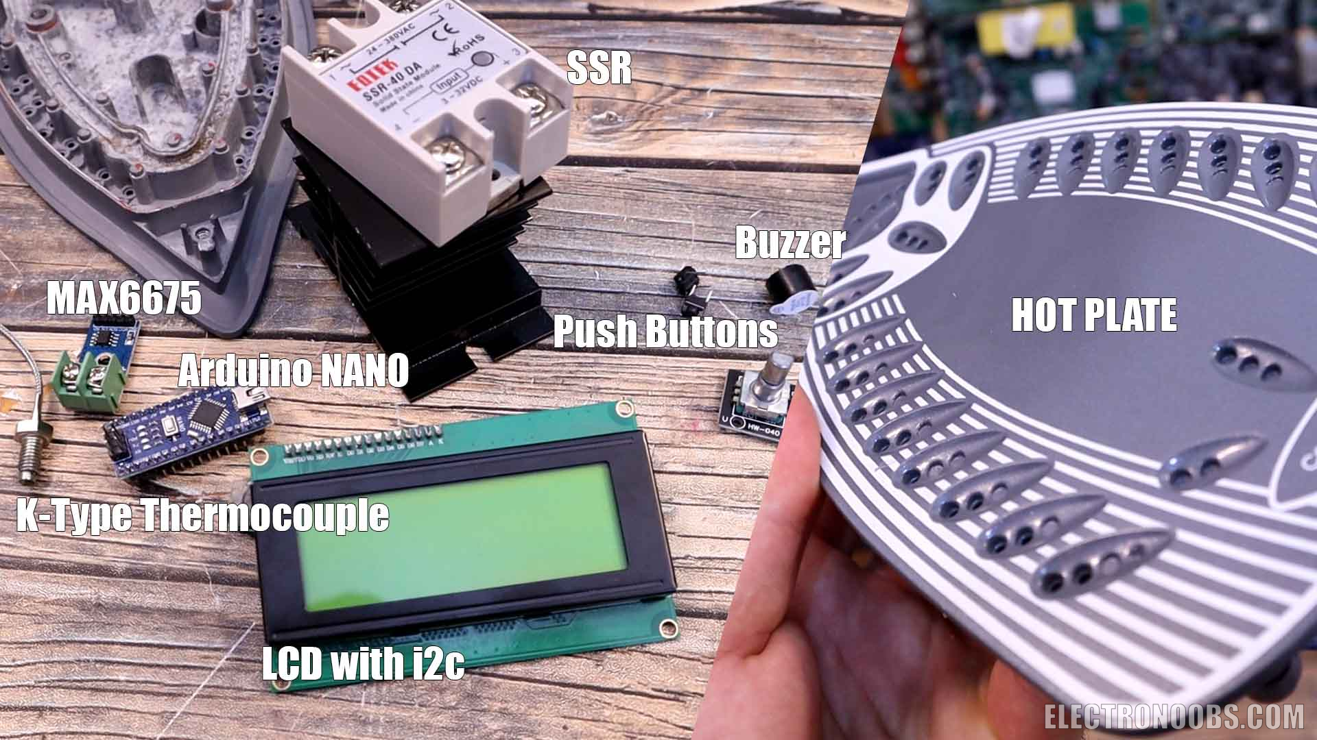
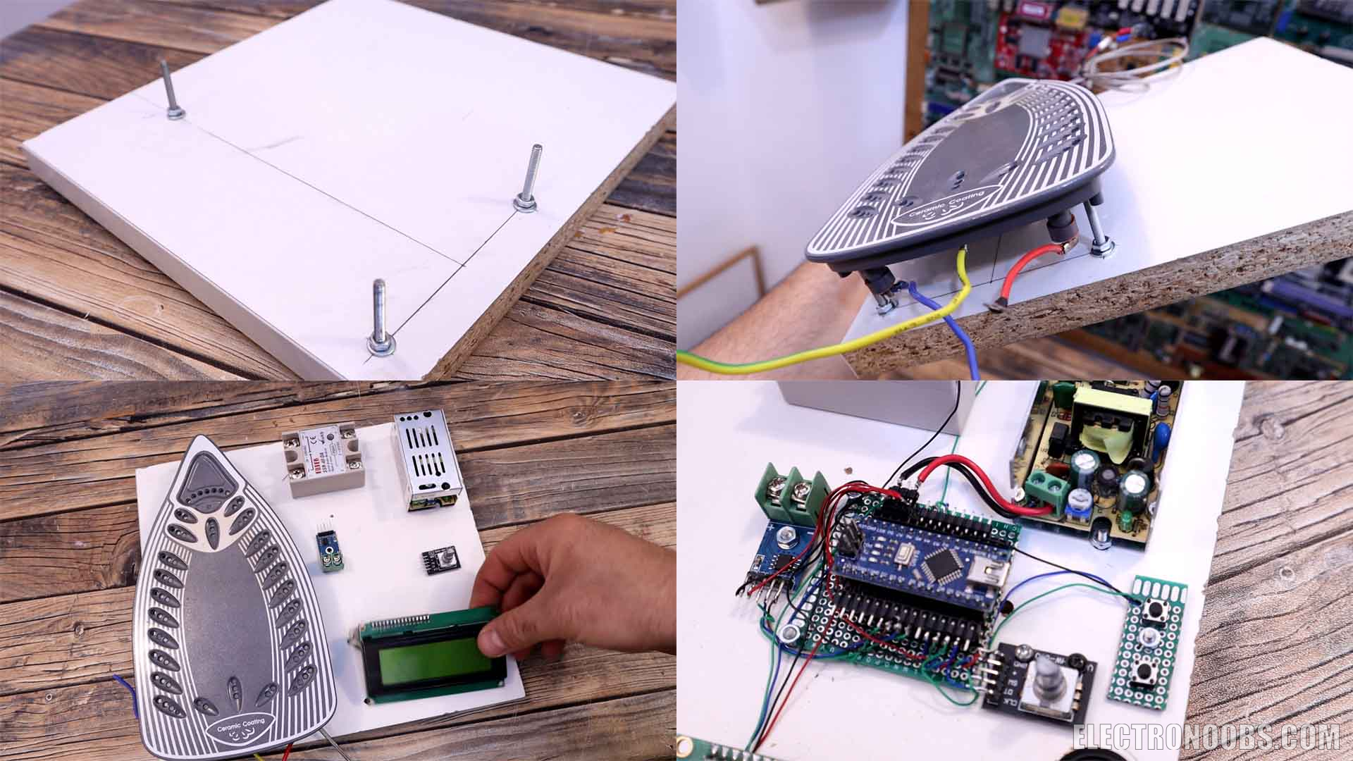
To control power we can use the solid-state relays or so called SSRs. These components already have the TRIAC and the firing circuit inside, we can easily control this with a 5V pulse from the Arduino. 3000W divided by 240V is around 13 amps of current. That’s why I bought some high-power relays, one is of 25 ampers. We could add a heat dissipator on top just to make sure I won’t burn them put or have any other problems. Finally, together with the Arduino we need a screen to show the temperature, power and setpoint values and some extra components such as some push buttons, maybe a buzzer and an LED or even a rotary encoder for adjusting the values. Have thick wires as well for the power connections. To supply the Arduino, we need 5V and I’ll get that with a cheap and simple switch mode power supply, in this way both the heater and the low voltage parts could be supplied with 240V from the main outlet. The rest of the components could be some wood for support, maybe screws and nuts, maybe some glue and so on. See full list below. So, let’s start.
- 1 x Chlotes Iron >2000W: LINK Aliexpress
- 1 x SSR 25A: LINK Aliexpress
- 1 x i2c LCD 20x4: LINK Aliexpress
- 1 x 5V 10W switched supply: LINK Aliexpress
- 1 x On/Off switch: LINK Aliexpress
- 2 x Push Buttons: LINK Aliexpress
- 1 x MAX6675 amplifier: LINK Aliexpress
- 1 x K-Type thermocouple: LINK Aliexpress
- 1 x Arduino NANO: LINK Aliexpress
- 1 x Buzzer: LINK Aliexpress
- Wires 20AWG: LINK Aliexpress
- 1 x prototyping PCB: LINK Aliexpress
- Female PCB pins: LINK Aliexpress
- 1 x wood base: Homemade
- M3 Screws: LINK Aliexpress
- 1 x carbon fiber vinyl: LINK Aliexpress
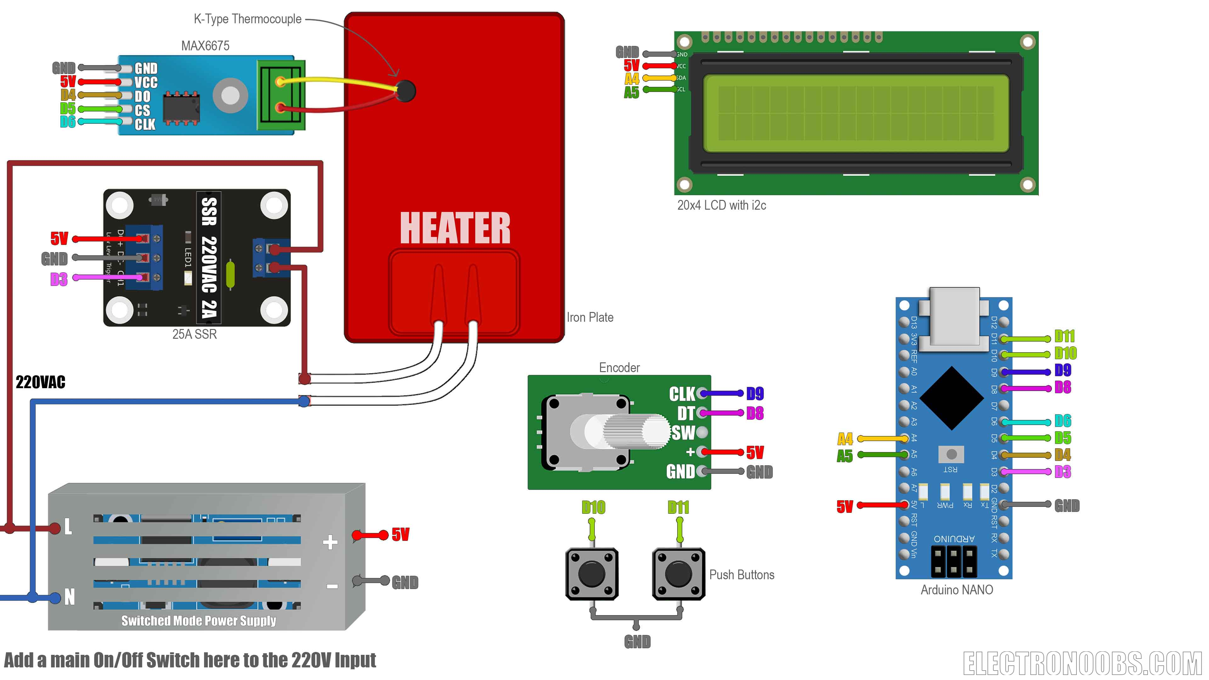
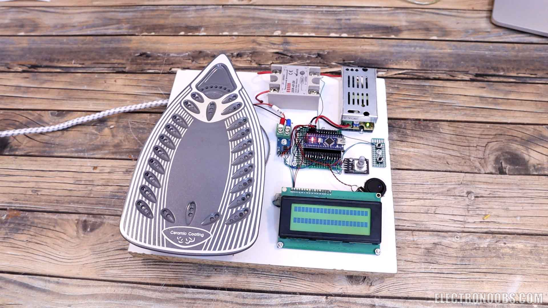
Get this schematic from below and have it in front of you so we could connect everything as in the schematic. The heater to the relay and the relay to the main 220V input with a mains wire. The same input is connected to the 5V power supply. The Arduino is connected to the LCD, to the buttons and the rotary encoder. Is also connected to the control pin of the relay. The thermocouple is connected to the MAX6675 module and the module is connected back to the Arduino. On the back I make connections to the power cord for earth and live input and that’s it.
In my case I have a chlotes iron for only 15 dollars and it is of 3000W. We need to open it and take it apart in order to see what connections we have and how we need to connect it. I take out a few screws and I open it and I can pull all the wires aside, because all we need is the heating element with the plate. I was expecting something more complex than this for the temperature control. Is nice to have the plate covered in ceramic since that will transfer heat very well, and ceramic irons use infrared energy that will get distributed consistently and uniformly over the plate.
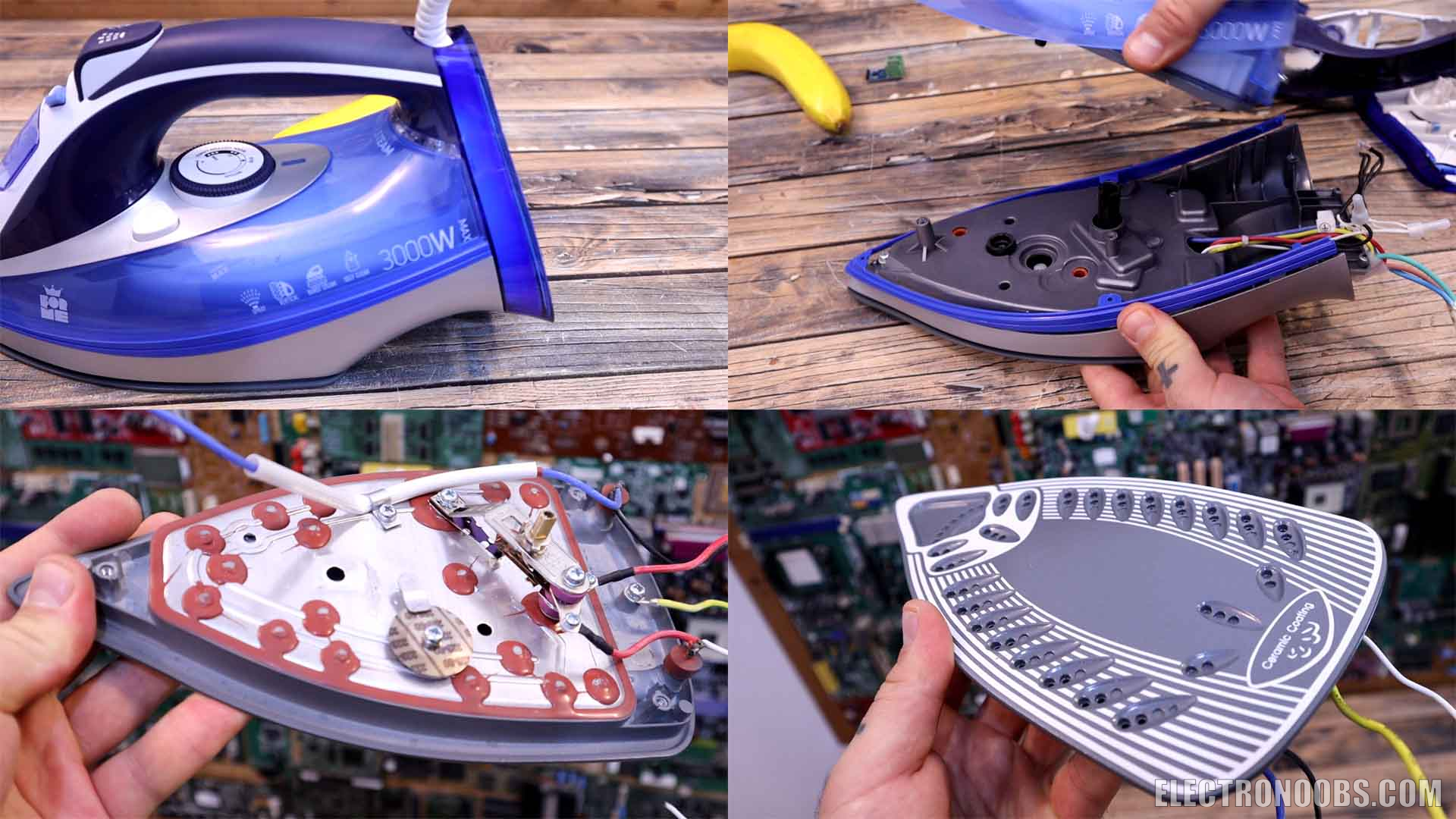
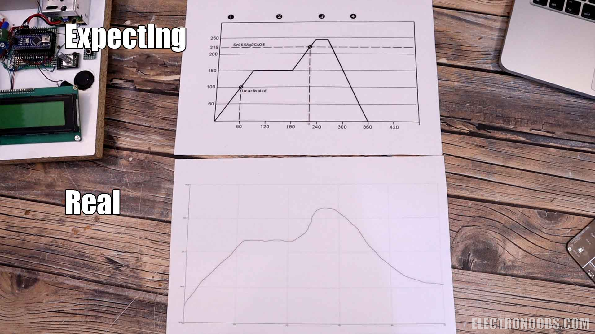
Before we go with more components, I first tape in place a K-Type thermocouple over the heating plate and connect it to my thermometer. I power on the heating plate without any safety or thermal switch in order to see if we can reach decent temperatures. We can reach over 300 degrees and that’s more than enough to melt the solder paste since a typical temperature curve for solder paste is something like you can see below, we don't overpass 200 degrees. I also had to remove the internal cover seal and take this cover out, because there was a lot of dust and residues that started to smoke when I was heating the plate. I've cleaned a little bit and now I think is better.
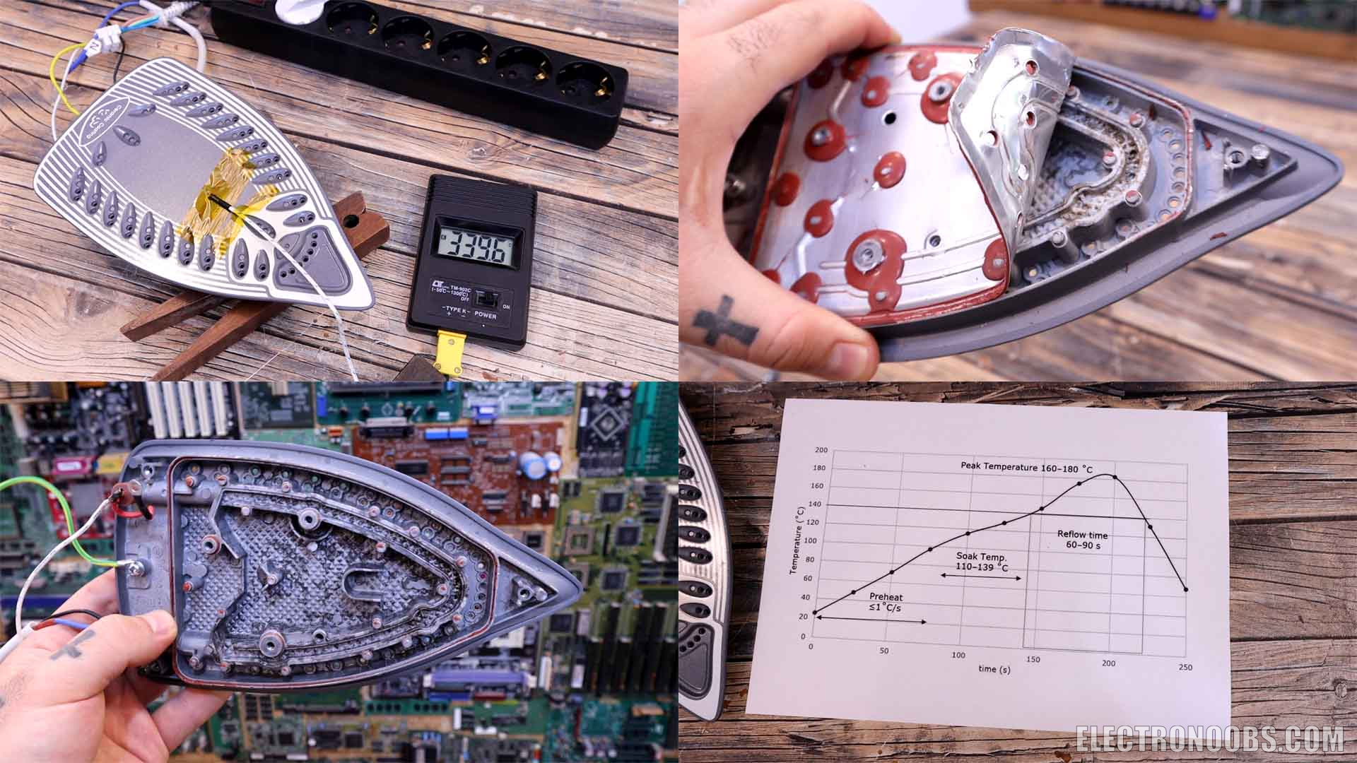
I select a spot where to place the thermocouple. I've made a hole and a thread o the bottom side so I can screw in palace the thermocouple and have perfect connection. I'm not sure if is a good idea to place two or three thermocouples in different spots so I can measure the temperature distribution. Just in case I've made another hole for a second thermocouple. Is obvious that the temperature will be higher at the beginning closer to the heating element and gradually dissipate towards the middle of the plate.
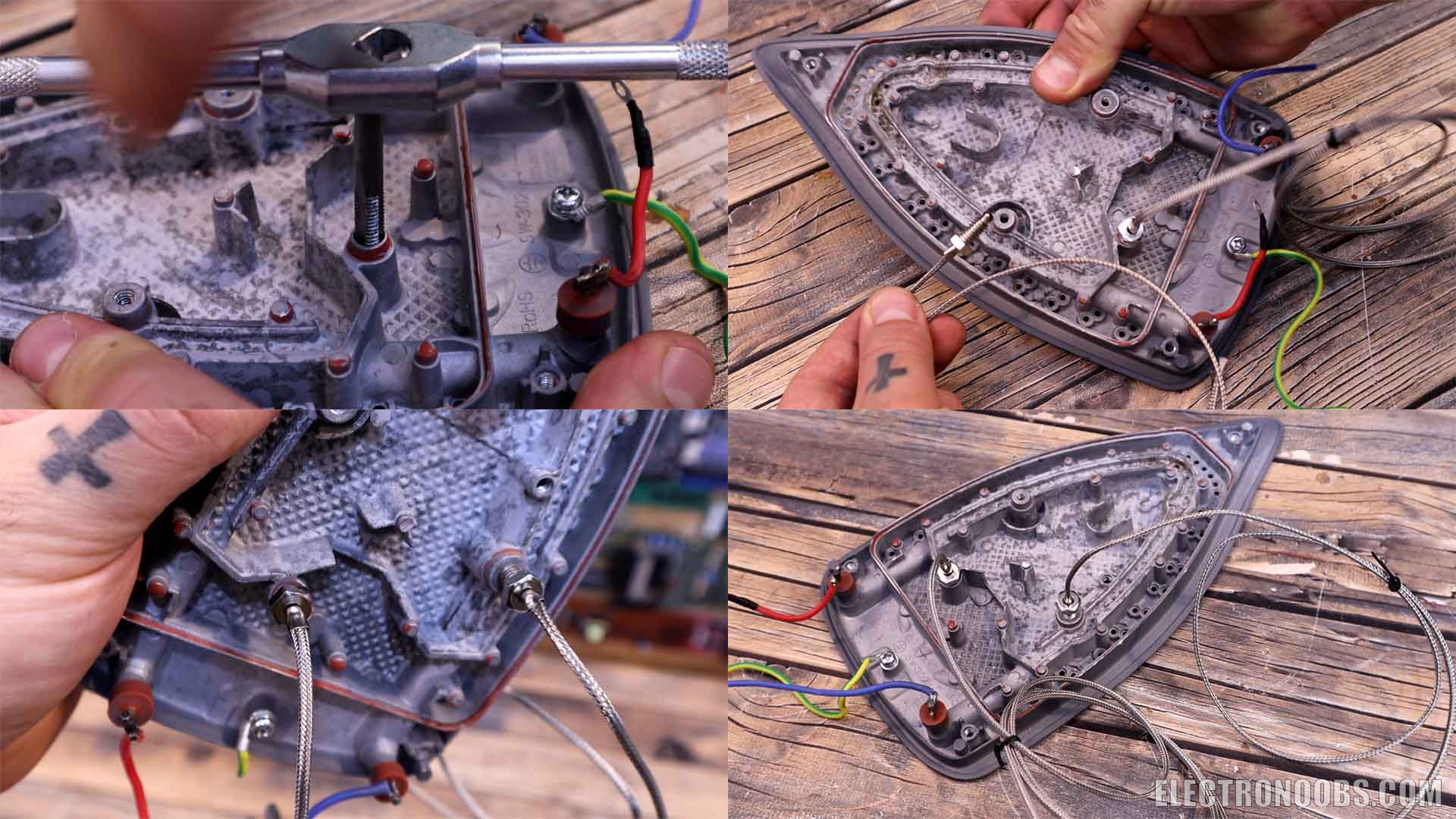
Once we have in place the thermocouple on the hole I've made before, I measure where I need the holes for 3 screws for the hot plate. I need to keep it in mid-air so it won't touch the wood and burn it. Now I can add some M4 screws and fix the hot plate in place. Next, I decide where to place each component. Just after I mark the spots I go and make the holes for each component except the Arduino. Then I screw in place everything. I finally decided to not use the heat dissipator for the relay and if it gets hot later, I will probably add this too. I've made a hole to add a main on and off switch for the 220V input. I solder the push buttons to some prototyping PCB. I add a PCB to the Arduino as well so I can make the connections easily. Once I screw in place these PCBs, we can make the connections with wires.
I connect everything as in the schematic. The heater to the relay and the relay to the main 220V input with a mains wire. The same input is connected to the 5V power supply. The Arduino is connected to the LCD, to the buttons and the rotary encoder. Is also connected to the control pin of the relay. The thermocouple is connected to the MAX6675 module and the module is connected back to the Arduino. On the back I make connections to the power cord for earth and live input and that’s it. Everything is in place and ready to go so is time for programming.
I uploaded my first version of the code. Now this is not PID control, have that in mind. Is just proportional control where I change the duty cycle, I count the elapsed time and measure the temperature and I try to get closer as I can to the curve shape of the sodler paste melting that found in the internet.
//Libraries
#include "max6675.h"              //Download it here: http://electronoobs.com/eng_arduino_max6675.php
#include <Wire.h>
#include <LiquidCrystal_I2C.h>    //Download it here: http://electronoobs.com/eng_arduino_liq_crystal.php
//Inputs Outputs
int SSR = 3;
int thermoDO = 4;                 //Data pin for MAX6675
int thermoCS = 5;                 //CS pin for MAX6675
int thermoCLK = 6;                //Clock pin for MAX6675
int DT = 8;                       //Data pin for encoder
int CLK = 9;                      //Clock pin for encoder
int but_1 = 11;                   //Button 1 input
int but_2 = 10;                   //Button 2 input
int buzzer = 12;                  //Buzzer output pin


MAX6675 thermocouple(thermoCLK, thermoCS, thermoDO);  //Start MAX6675 SPI communication
LiquidCrystal_I2C lcd(0x27,20,4);                     //Address could be 0x3f or 0x27

//Variables
unsigned int millis_before, millis_before_2;
unsigned int millis_now = 0;
int refresh_rate = 1000;
int pid_refresh_rate = 300;
unsigned int seconds = 0;
int running_mode = 0;
int selected_mode = 0;
int max_modes = 1;
bool but_1_state = true;
bool but_2_state  =true;
float pwm_value = 5;
int max_pwm_value = 40;
int min_pwm_value = 2;
float temp_setpoint = 0;
float temperature = 0;

void setup() {
  //Define the OUTPUTs
  pinMode(SSR, OUTPUT);       //Start with the SSR off
  digitalWrite(SSR, LOW);
  pinMode(buzzer, OUTPUT);    //Start with buzzer off
  digitalWrite(buzzer, LOW);

  //Define the INPUTS
  pinMode(DT, INPUT_PULLUP);
  pinMode(CLK, INPUT_PULLUP);
  pinMode(but_1, INPUT_PULLUP);
  pinMode(but_2, INPUT_PULLUP);

  Serial.begin(9600);
  lcd.init();                 //Init the LCD
  lcd.backlight();            //Activate backlight

  millis_before = millis();
  millis_now = millis();

}

void loop() {
  millis_now = millis();
  if(millis_now - millis_before_2 > pid_refresh_rate){
    millis_before_2 = millis();
    temperature = thermocouple.readCelsius();
    if(running_mode == 1){
      if(temperature < 150){
        temp_setpoint = seconds;
        if(temp_setpoint > temperature){
          pwm_value = pwm_value + 0.3;
          if(pwm_value > max_pwm_value){
            pwm_value = max_pwm_value;
          }
        }
        else{
          pwm_value--;
          if(pwm_value < min_pwm_value){
            pwm_value = min_pwm_value;
          }
        }
      }
      else if(temperature > 140){
        max_pwm_value = 60;
        temp_setpoint = 200;
        if(temp_setpoint > temperature){
          pwm_value = pwm_value + 0.3;
          if(pwm_value > max_pwm_value){
            pwm_value = max_pwm_value;
          }
        }
        else{
          pwm_value--;
          if(pwm_value < min_pwm_value){
            pwm_value = min_pwm_value;
          }
        }
      }

      analogWrite(SSR, pwm_value);  //We change the Duty Cycle

      if(temperature > 190){
        running_mode = 10;
        analogWrite(SSR, LOW);
      }
    }//end of running_mode == 1

    if(running_mode == 10){
      lcd.clear();
      lcd.setCursor(0,1);
      lcd.print("      COMPLETE      ");
      tone(buzzer, 1000, 1000);
      seconds = 0;              //Reset timer
      running_mode = 11;
      delay(2000);
    }
  }//end of pid_refresh_rate


  if(millis_now - millis_before > refresh_rate){
    millis_before = millis();
    seconds = seconds + (refresh_rate/1000);      //We count time
    Serial.println(temperature);

    if(running_mode == 0){
      digitalWrite(SSR, LOW);
      lcd.clear();
      lcd.setCursor(0,0);
      lcd.print("Temp: ");
      lcd.print(temperature,1);
      lcd.setCursor(0,1);
      lcd.print("SSR: OFF");
      lcd.setCursor(0,2);
      lcd.print("SELECTED MODE: ");
      lcd.print(selected_mode);
      lcd.setCursor(0,3);
      lcd.print("NOT RUNNING");
    }//end of running_mode == 0

    else if(running_mode == 11){
      if(temperature < 40){
        running_mode = 0;
         tone(buzzer, 1000, 100);
      }
      digitalWrite(SSR, LOW);
      lcd.clear();
      lcd.setCursor(0,0);
      lcd.print("Temp: ");
      lcd.print(temperature,1);
      lcd.setCursor(0,1);
      lcd.print("SSR: OFF");
      lcd.setCursor(0,2);
      lcd.print("SELECTED MODE: ");
      lcd.print(selected_mode);
      lcd.setCursor(0,3);
      lcd.print("COOLDOWN");
    }//end of running_mode == 0


    else if(running_mode == 1){
      lcd.clear();
      lcd.setCursor(0,0);
      lcd.print("Temp: ");
      lcd.print(temperature,1);
      lcd.setCursor(0,1);
      lcd.print("SSR: ON ");  lcd.print("Time: "); lcd.print(seconds);
      lcd.setCursor(0,2);
      lcd.print("SELECTED MODE: ");
      lcd.print(selected_mode);
      lcd.setCursor(0,3);
      lcd.print("RUNNING | PWM: ");  lcd.print(pwm_value,1);
    }//end of running_mode == 1
  }//end of millis_now - millis_before > refresh_rate


  ///////////////////////////////////////////////////////////////////
  ///////////////////////////////////////////////////////////////////
  if(!digitalRead(but_1) && but_1_state){
    but_1_state = false;
    selected_mode ++;
    millis_before = millis_before-1000;
    if(selected_mode > max_modes){
      selected_mode = 0;
    }
  }
  else if(digitalRead(but_1) && !but_1_state){
    but_1_state = true;
  }
  ///////////////////////////////////////////////////////////////////
  if(!digitalRead(but_2) && but_2_state){
    if(running_mode == 1){
      digitalWrite(SSR, LOW);
      running_mode = 0;
      selected_mode = 0;
    }

    but_2_state = false;
    if(selected_mode == 0){
      running_mode = 0;
    }
    else if(selected_mode == 1){
      running_mode = 1;
      tone(buzzer, 1000, 1000);
      seconds = 0;              //Reset timer
    }
  }
  else if(digitalRead(but_2) && !but_2_state){
    but_2_state = true;
  }
  ///////////////////////////////////////////////////////////////////
  ///////////////////////////////////////////////////////////////////

}//end of void loop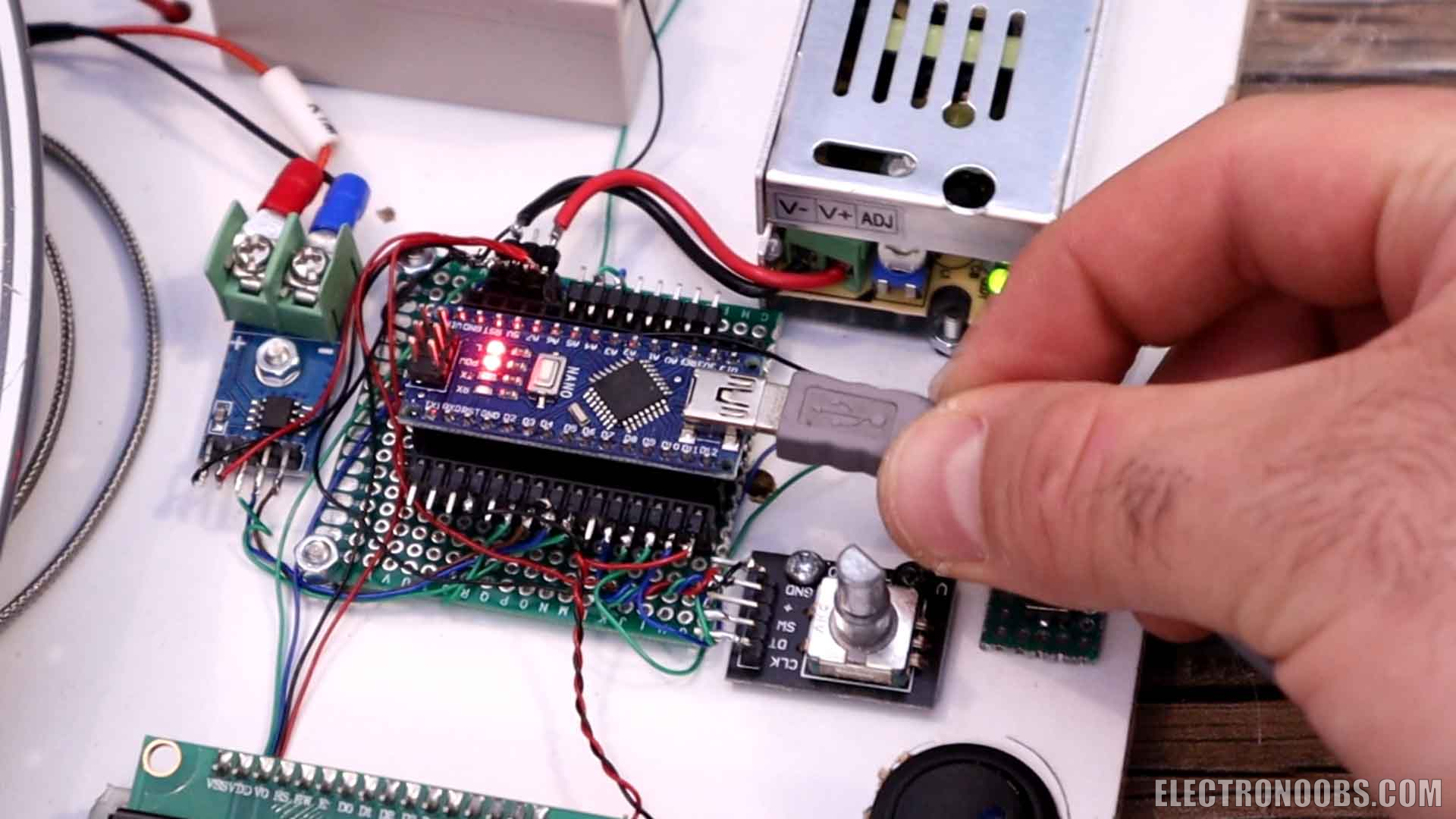
I first secure my test PCB in place with some other PCBs. Then I get my SMD stencil and fit it exactly on top. I add solder paste and using a spatula I fill all the holes evenly. Finally, I end up with the exact amount of paste for each pad so now I can add the components one by one. I didn't fill the entire PCB but I've placed a few resistors, capacitors, transistors and some regulators. I power on the hot plate and place the PCB on top. I select mode 1 and press ok. We can hear a beep and now the code is running. You can also see a red light turning on the relay very dim because we start with low PWM values. The temperature raised a bit too hard but I got good results. Below you have a fast replay of the components getting soldered, is actually quite amazing how professional it looks. The components look like they were soldered by professional machines. Even the 0402 resistors got soldered perfectly. On the other side, these voltage regulators also have good solder connections. The same for the capacitor and the inductor as well.
I've made changes in the code and run it again with a different PCB but with only a few components. This time the temperature curve was better and I had no spikes. The components got soldered with no problems. During tests I realized that the perimeter zone is getting hot a lot faster than the middle area, since that's where the heating element is passing. This might give us problems for big PCBs, since the temperature is not even. I've changed the code like 10 times and I've also made a serial print of the temperature each second so I could run the serial plotter of the Arduino and get a graph. The first runds were not exactly what I was expecting but is a good result for me for just a few tests. But I've made more and more tweaks in the code till I got the curve you can see below which is pretty decent. I will improve this code the best I can and maybe even apply a true PID control.
In the end I didn't used the rotary encoder, but I will probably use it for future updates of this project. I'm really satisfied with the results so far, because this means I could now solder my PCB panels that I've ordered from PCBWAY and finish my product. But this project is for another video, so stay tuned. In the end, I've took everything out and wrapped the wood board in some carbon fiber vinyl so it would look better. Then I've screwed back in place the components and the project is finish. If you like this video and you've learned something new, give me a like or comment below. Thanks again and see you later guys. If my videos help you, consider supporting my work on my PATREON or a donation on my PayPal. Thanks again and see you later guys.
Comments


Leave a comment
Please login in order to comment.