
Here we are with another episode of the Arduino 101 series, which if you remember are tutorials about Arduino but not basic any more, we learn some more in-depth stuff about this microcontroller. Today we will learn about all the blocks of the analog to digital converter or ADC. What registers we need to work with, how to define the analog reference, the sample rate prescalar, select the INPUTS with the multiplexor, and quite interesting, how to read the internal temperature sensor. Because yes, the Arduino has an internal temperature sensor. So basically, we will learn what the analogRead function dose. When this video is over, you should know what each of the ADC blocks will do. So guys, let’s get started.
What’s up my friends, welcome back. We will talk about the Arduino UNO for the examples and if you want to know more about any other Arduino model, just check the same registers in the datasheets of the other microcontrollers. Remember that the ATmega328p microcontroller has 8 analog inputs for the AU version and 6 analog inputs for the PU version. We use these inputs to measure voltage and pass from analog to digital values, which in this case, the Arduino UNO has a 10 bits ADC so digital values from 0 to 1023. But there is a little bit more than the well-known analogRead function, so let’s dive in. These below are the blocks used for the analog to digital conversion and by the end of the post you should know what each of this block dose. Here we have two main registers and we will learn what each of their bits do in the code, registers ADMUX and ADCSRA.
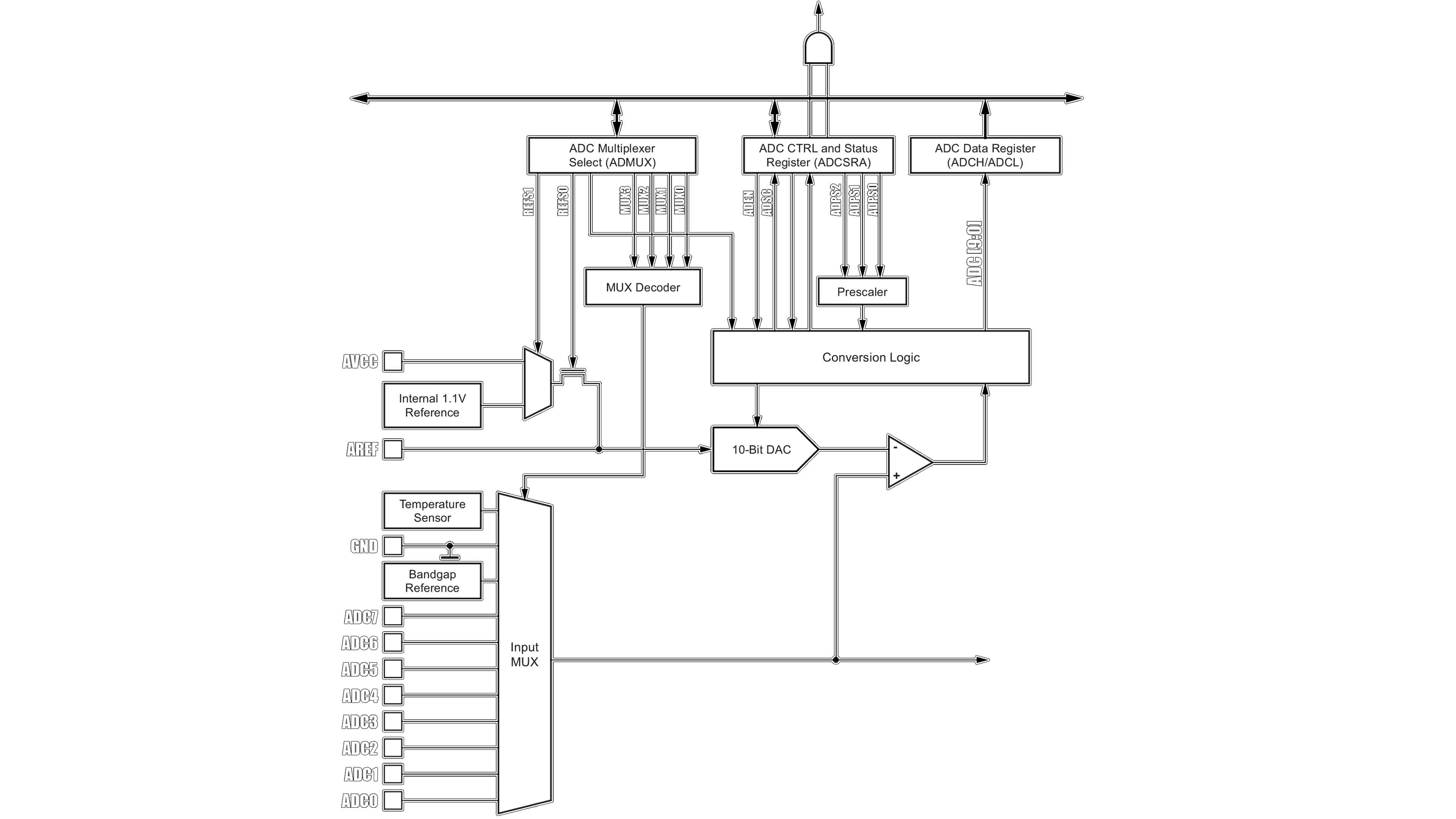
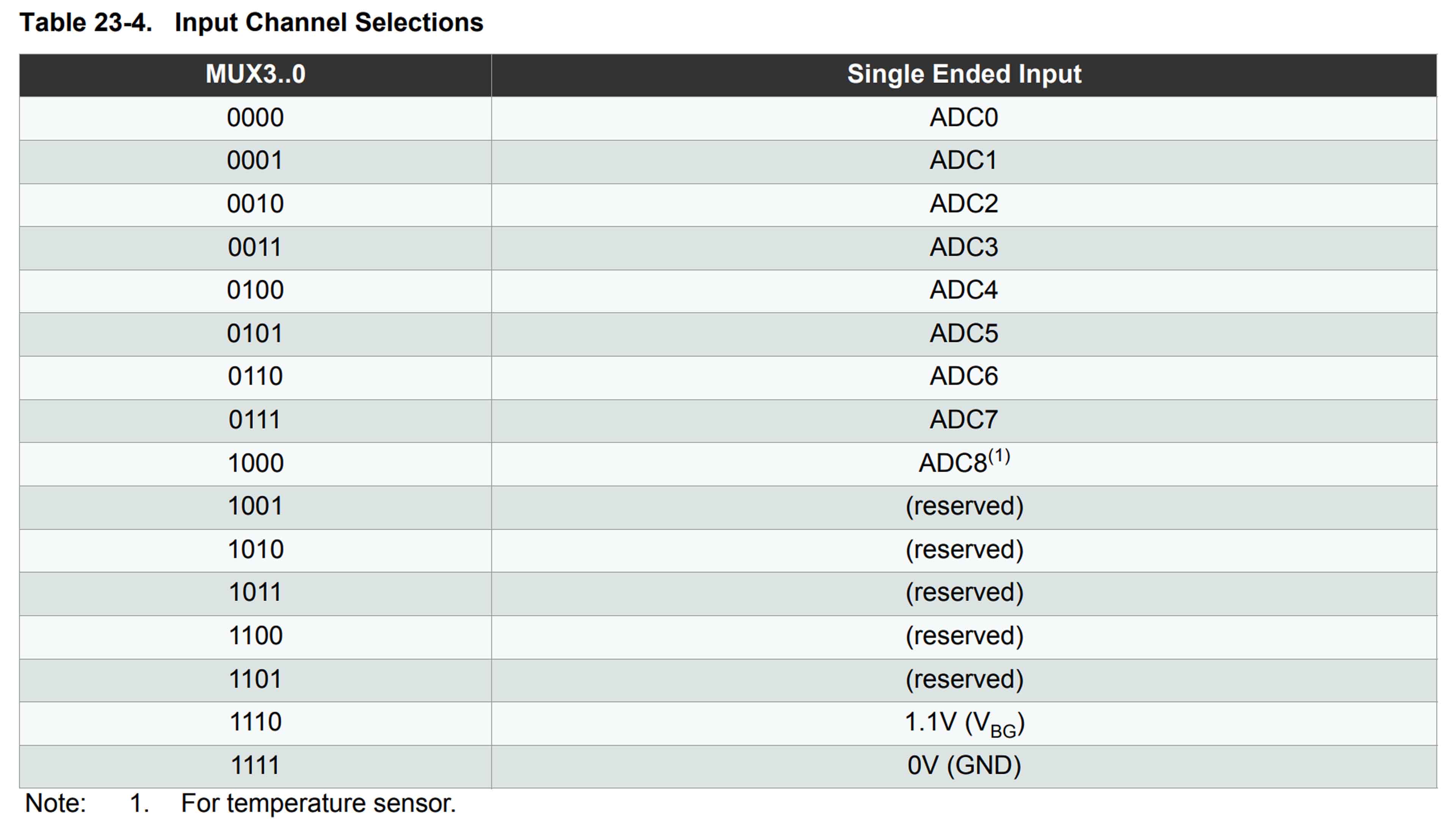
First, let’s select the input for the ADC. We have just one ADC conversion block so we need to select each input separately and make the measurement. As you can see the multiplexor for the input is controlled with 4 bits from MUX0 to MUX3. These bits are from the ADMUX register. So if these bits are "0000", the ADC input will be the A0 pin, if the bits are 0001 it would be A1, 0010 it would be A2 and so on as in the table below. So in the code, if you want to read the A4 input for example we make this line. ADMUX OR equal to 0000 0100 so A4 is connected to the ADC conversion block.
void setup {
  ADMUX |= B00000100;  //A4 is connected to the ADC logic
}
void loop {
}
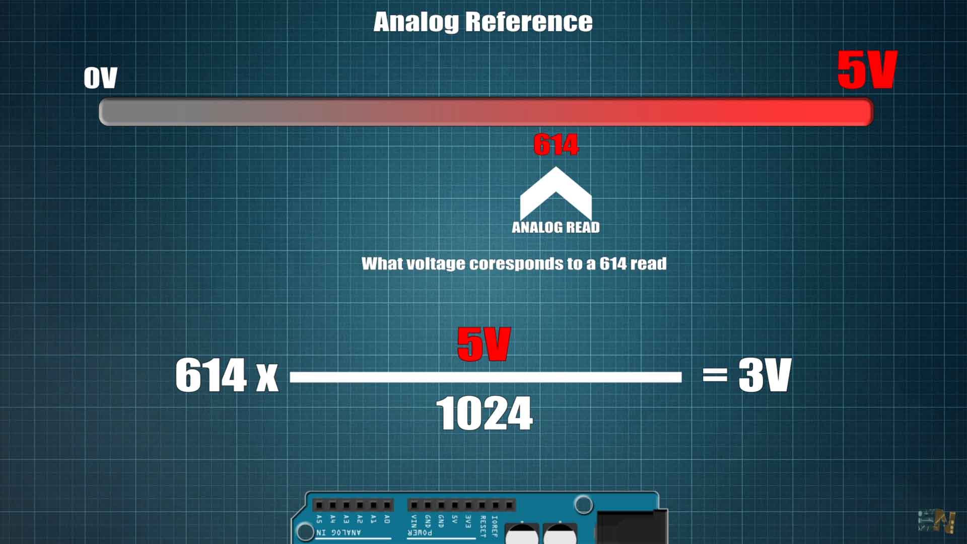
Now we need to indicate the voltage reference. What is that? Well, in order to make the conversion, the ADC needs to compare the analog input with a known value which by default is the microcontroller supply, the VCC line. Otherwise you wouldn’t know what are you reading. Usually, VCC for the Arduino is 5V. So, in this way the Arduino knows that maximum, so 1023 would be for 5V and minimum would be for 0V. So, imagine that you make a measurement and the analog read gives you a value of 614, let’s say. What voltage is that? Well, what we usually do in the code to pass from digital values to voltage values is to divide the analog reference voltage by the maximum digital value, which is 1024. Then we multiply that value by the analog read which was 614 and we would get a read of 3V. But this implies that the reference voltage is 5V. But I can assure you, this is never true. The Arduino board uses a voltage regulator to get 5V. The output from this is sometimes 4.9, sometimes 5.1 or a value in between. That means the analog read we have made before is not precise.
Another example is when we supply the Arduino with a battery. As you know, the Arduino could work with no problems with voltages above 2.5V, so for example we connect a 4.2V battery to the VCC pin. Now the analog reference is not 5V anymore, is 4.2 so the code would be affected.
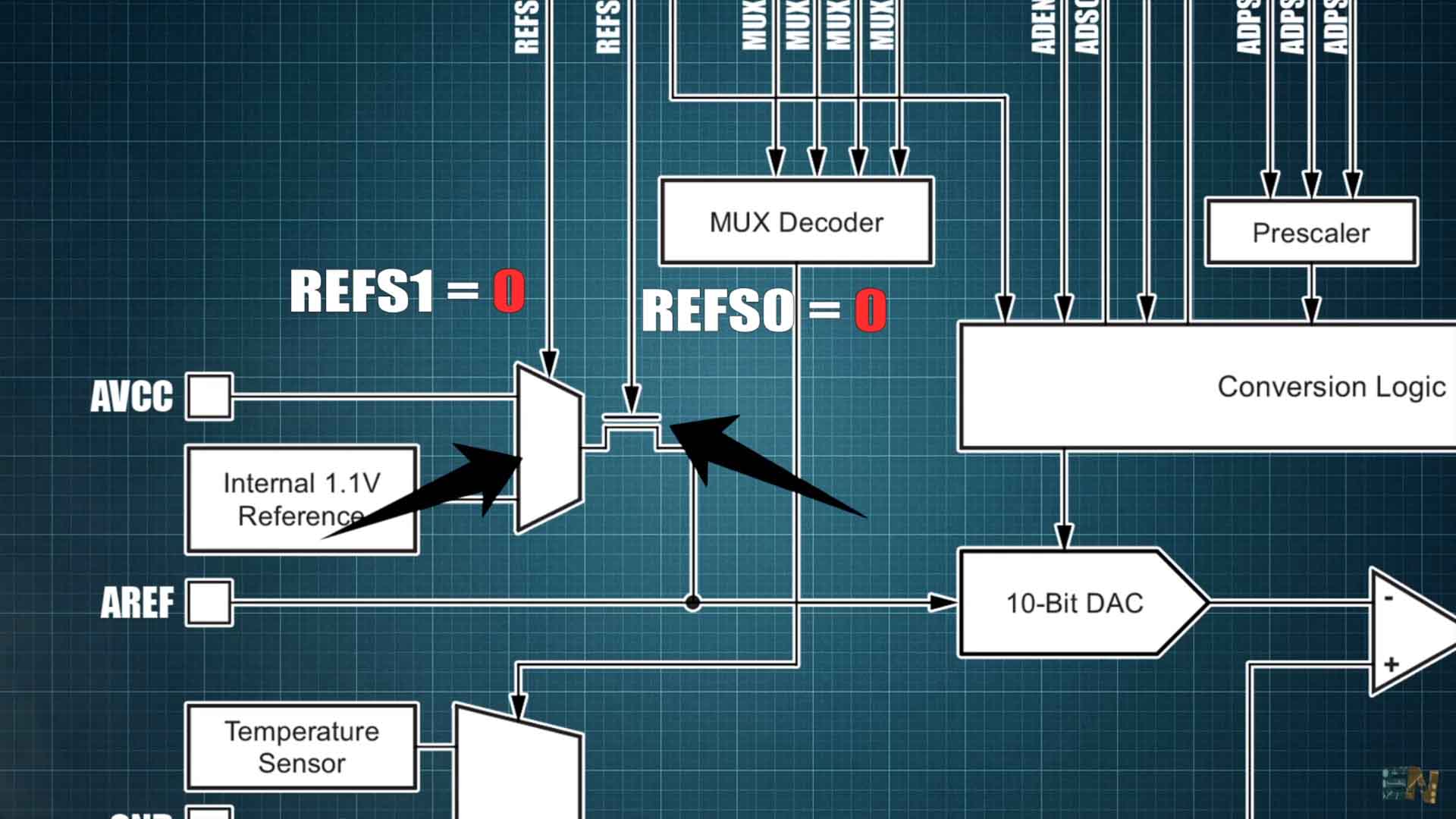
For more precise reads, the Arduino chip has an internal voltage reference that usually is more precise. For Arduino UNO we have a 1.1V internal reference but the Arduino MEGA also has a 2.56V reference. The reference could also be external, in this case it would be any voltage that you connect at the AREF pin of the board. So if you connect 3V, for example, the reference would be 3V. But in order to select these analog references we need to set them in the code. As you can see here, to select between these 3 reference inputs, we use the REFS1 and REFS0 bits. If both bits are 0, that means the mux and the selector FET are disabled, so the reference would be external from the AREF pin. If the REFS0 is a 1, then we can select between VCC and internal reference with the REFS1 bit. If REFS1 is 0, then the reference is VCC. And if is a 1, the reference is the internal 1.1V. These 2 bits are from the ADMUX register, bits 6 and 7. So in order to select the internal reference in the code, we make ADMUX OR equal to 11000000 so those two bits are 11.
void setup {
  ADMUX |= B11000000;  //REFS0 and REFS1 are "1" so INTERNAL 1.1V reference selected
}
void loop {
}
If you don’t want to use registers, you can also do these lines with this function in the code, analog reference and add the type which could be any of these values depending on the Arduino Model.
● DEFAULT: the default analog reference of 5 volts (on 5V Arduino boards) or 3.3 volts (on 3.3V Arduino boards)
● INTERNAL: a built-in reference, equal to 1.1 volts on the ATmega168 or ATmega328P and 2.56 volts on the ATmega32U4 and ATmega8 (not available on the Arduino Mega)
● INTERNAL1V1: a built-in 1.1V reference (Arduino Mega only)
● INTERNAL2V56: a built-in 2.56V reference (Arduino Mega only)
● EXTERNAL: the voltage applied to the AREF pin (0 to 5V only) is used as the reference.
void setup {
  analogReference(INTERNAL);  //INTERNAL 1.1V reference selected
}
void loop {
}
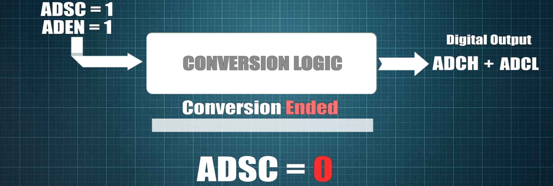
Ok, so now we have the ADC input selected and the reference as well. All we need is to make the conversion which is controlled with the ADCSRA register. To start the conversion, we need to put the ADEN and ADSC bits to "1". Then we wait till the conversion is over and we will have the digital value on the ADCH and ADCL bytes where the H and L stands foe High and Low sides of the value. So in the code we make ADCSRA OR equal to 11000000 and that will start the conversion. Then how do we know when the conversion is done? Well, we can make a while and inside this while we can place, "if bit is set", and select the ADSC bit of the ADCSRA register. Because this bit will automatically go to 0 when the conversion is over, so while AD SC is 1, the conversion is still going.
Finally, our digital value is equal to the high side of the read plus the low side of the read with a total of 10 bits. So we sum the low side with the high side but shifting 8 bits to the left so when we merge them together it would represent 16 bits. That’s it, that’s how you make the analog read using registers. Look, I upload this code to the Arduino and get the analog read on my monitor, the same as if I were to use the analogRead functions. But his time this is made with registers so we have learned something new.
void setup() {
  Serial.begin(9600);
}

void loop() {
  //REFS1 AND REFS0 to 1 1 -> internal 1.1V refference
  ADMUX |= B11000000;
  //We read A1 (MUX0)
  ADMUX |= B00000001;

  // Start AD conversion
  ADCSRA |= B11000000;
  // Detect end-of-conversion
  while (bit_is_set(ADCSRA,ADSC));
  int val = ADCL | (ADCH << 8);
  Serial.println(val);
}
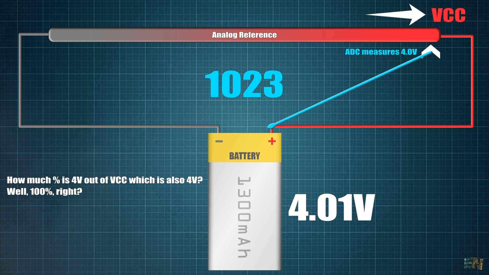
But let’s see why we should use the internal voltage reference of 1.1V. Remember my smartwatch project. In that project I was measuring the voltage of the battery in order to print it on the screen. Is quite common for electronic devices to do that, even your smartphone will show you the battery percentage, right? But this is the problem: I want to measure the battery voltage, but the analog reference is the battery itself, because the battery is the supply of my Arduino. So let’s say the battery is charged to 4V for example. I make the ADC conversion and the chip will compare the measured 4V with the analog reference, which, if is defined to be by default the VCC value, it would be 4V as well. So the ADC would give us the maximum value which is 1023. But after a while the battery voltage decreased to 3.8V. Now we measure with the ADC 3.8V but the VCC is also 3.8V, so the analog read will give us maximum once again. So you see the problem? Without an external voltage reference, the Arduino would think the battery is always full.
If I define in the code the ADC reference to be the fixed value of 1.1V, this voltage won’t change Its value with the battery. So now we could measure the battery voltage while supplying the Arduino with that same battery. All we have to do is to add a voltage divider from the battery to the ADC input in order to lower the voltage to below 1.1V since that is our maximum value if we use the internal reference. So this below would be the code if you want to read the voltage using the internal reference and a voltage divider of 1K and 4.7K.
void loop() {
  //REFS1 AND REFS0 to 1 1 -> internal 1.1V refference
  ADMUX |= B11000000;
  //We read A1 (MUX0)
  ADMUX |= B00000001;
  // Start AD conversion
  ADCSRA |= B11000000;
  // Detect end-of-conversion
  while (bit_is_set(ADCSRA,ADSC));
  float val = ADCL | (ADCH << 8);
  val = val * 5.7; //Multiply by the inverse of the divider
  Serial.println(val);
}
Remember that I’ve told you the Arduino had an internal temperature sensor. If we take a look at the ADC blocks, that sensor is connected at the input 11. So if we set the ADMUX to have the MUX bits to 1000, then, the sensor is connected to the ADC conversion block. The sensitivity of this sensor is approximately 1mV for Celsius degree and is quite a bad sensor with an accuracy of plus minus 10 degrees. But anyway, we make this code and we set ADMUX OR equal to 00001000 so the sensor is now connected to the ADC. According to some internet values, we have to divide the analog read by 1.22 and also subtract the offset. And this would be the temperature in Celsius degrees. I upload this code and run the serial plotter. As you can see, when I heat the chip, the temperature goes up and that’s it. You could use this to monitor more or less the IC temperature.
void setup() {
  Serial.begin(9600);
}

void loop() {
  ADMUX |= B00001000;     //We read A8 (Temp Sensor)
  ADMUX |= B11000000;     //(INTERNAL 1.1V Reference)
  ADCSRA |= B11000000;    //ADEN and ADSC equal to 1   (Start conversion)

  while(bit_is_set(ADCSRA, ADSC));    //Wait for conversion to end
  long raw_temp = ADCL | (ADCH << 8);   //Get analog read value

  // f(x) = (raw - offset) / coeff
  long temperature = (raw_temp - 53)/1.22;
  Serial.println(temperature);
  delay(500);
}Now you know how all these blocks work and which registers you need to control in order to make the conversion. Also, why the internal reference is important. If you like this video and you've learned something new, give me a like or comment below. Thanks again and see you later guys. If my videos help you, consider supporting my work on my PATREON or a donation on my PayPal. Thanks again and see you later guys.


