I have a new radio controller project and I think it looks a lot better than my previous controller. This one is based on the STM32 so it could get a lot faster and have more modes and options without creating big delays. Compared with my previous radio controller that was based on the Arduino, this new model also has a better, bigger, color and touchscreen display. I’ve designed this PCB for this project and we can solder all the modules here. The PCB looks awesome and perfectly fits inside my 3D design for the case. Is supplied by two 18650 batteries. The joysticks that I’ve used are also are better then some of my previous radio controllers.
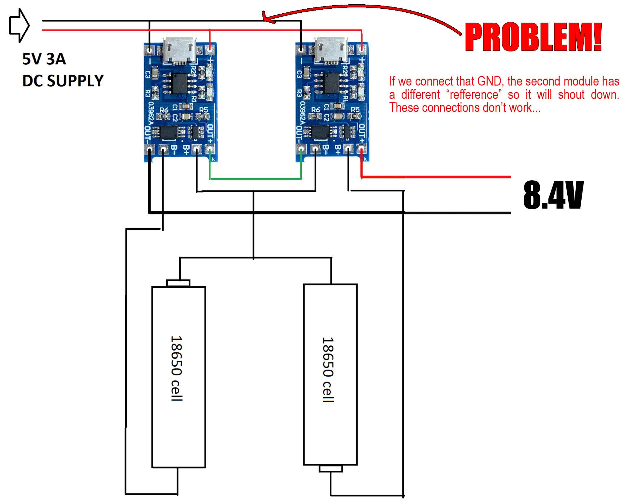
Ok, so first, in the video I've made some mistakes with the charging system with those TO4056 so I've changed the schematic and on this page you will find the new one. I first wanted to use two TP4056 modules in series to be able to charge my batteries using a USB cable because that's convenient. But once I've made tests, I realized that the output of 8.4V dorops to 4.2V once we make a GND connection between the inputs of both mdoules. We need that GND connection in order to supply 5V to both mdoules at the same time so they will both charge its battery. But that's doesn't work becuase one of the modules, now has a different GND refference and will shut down the output. That's why I will make a different approach but with more components. See that next.
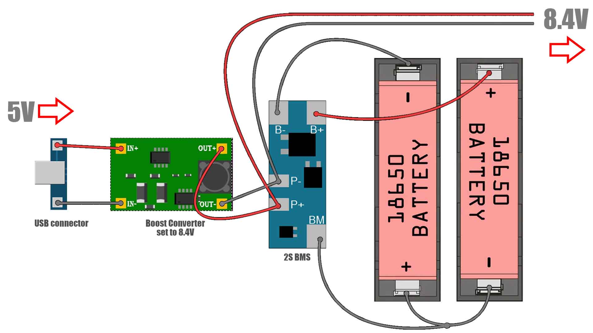
The different approach is something that I've already used in the past but it needs more components. This time we can use a dedicated 2S BMS charger to charge and protect the batteries. But in this way, we can't use directly the USB connector as an input because the BMS needs exaclty 8.4V at the input for charging and not 5V as the USB has. That's why in between we can add a boost converter set to 8.4V connected with its output at the BMS P+ and P-, which are the Input/Output pads. Another option would be to get rid of the USB connector and the boost converter and directly buy a 8.4V adaptor like this one and use it to charge the controller. I wanted a USB connector because is more convenient. But you can go with the option that you prefer.
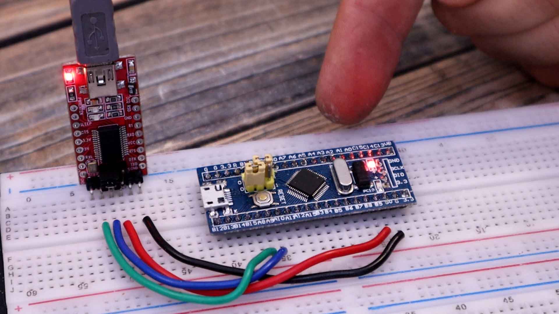
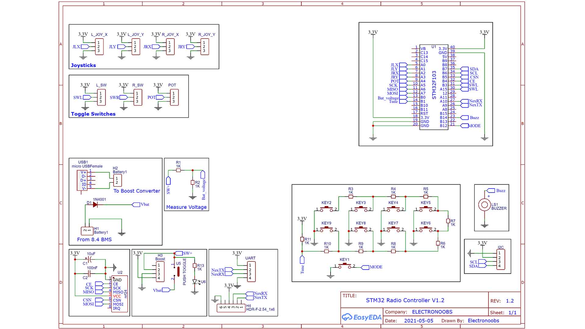
Ok, below you will find the basic configuration of this microcontroller. So in order for it to work, at least we need these components. It needs a pullup on the reset pin and we need the 8MHz crystal and 32KHz resonator each with two 20pF capacitors connected. To get 3.3V I’ve used the AMS1117 regulator and supplied the output to the VDD pins. For the boot1 and boot 2 connections I’ve placed 6 pins so I could also use jumpers to make the switch.
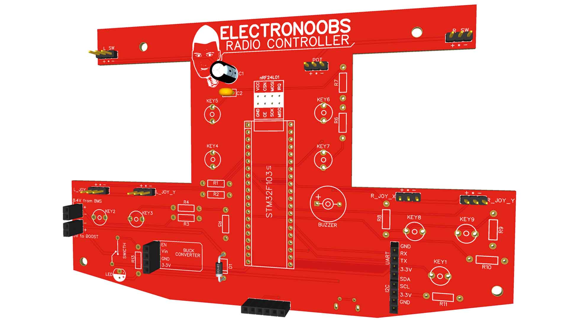
As you can see, comapred with the PCB in the video, the schematic is now changed. We don't have the TP4056 modules anymore. In this case we just have a micro-USB connector for 5V. That is connected to an external boost converter and the converter is connected to the external 2S BMS. The BMS is connected to the batteries as we have seen before and then the 8.4V output is connected back to the PCB. We have some female connectors for that, H1 and H2 on the schematic.
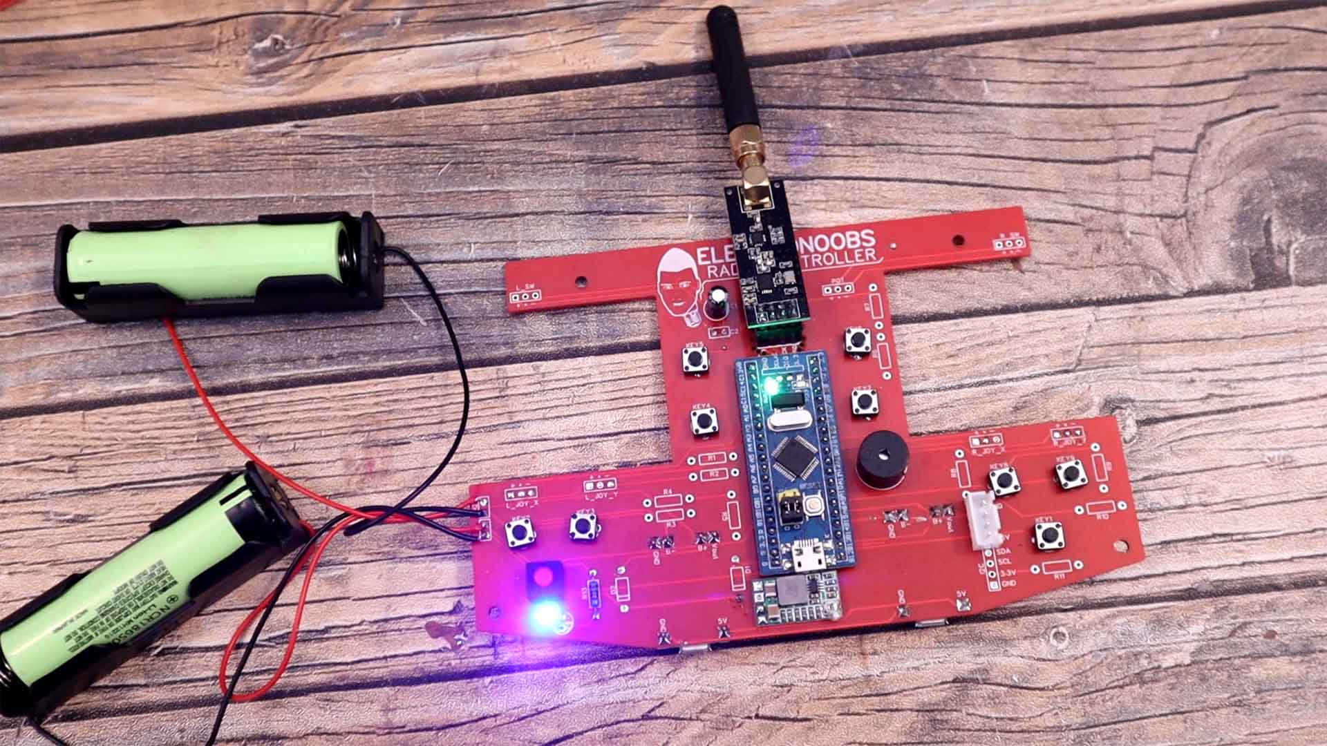
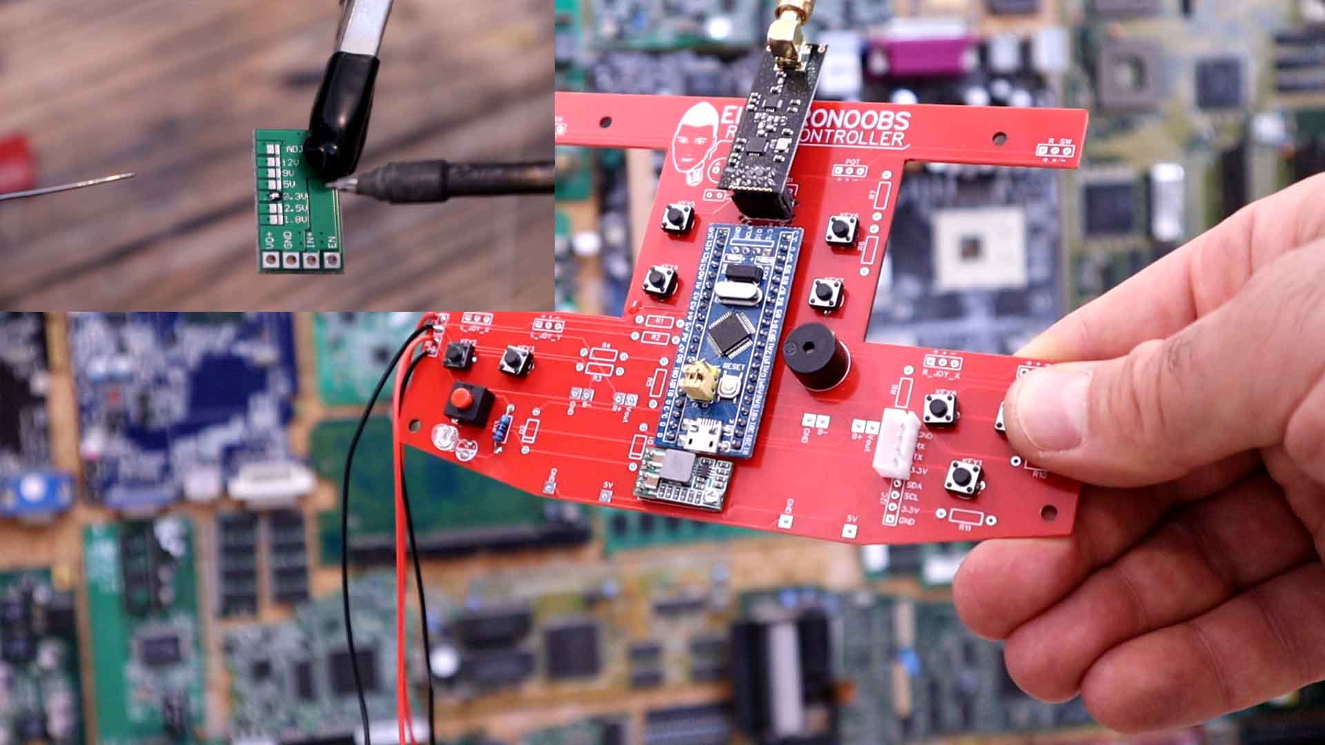
I ended up with this PCB for the new version and in the middle, we have the STM32. I’ve got the PCB from PCBway and the quality is great. We have a palce for the STM in the middle, 4 pins for the small buck converter to get 3.3V, for the buzzer, for the UART pins of the NEXTION display, for the battery 8.4V Input and for the 5V taht should go to the boost external converter. That's pretty much it.
Remember that the battery circuit is external. So from the PCB we get 5V and connect it to the boost converter.
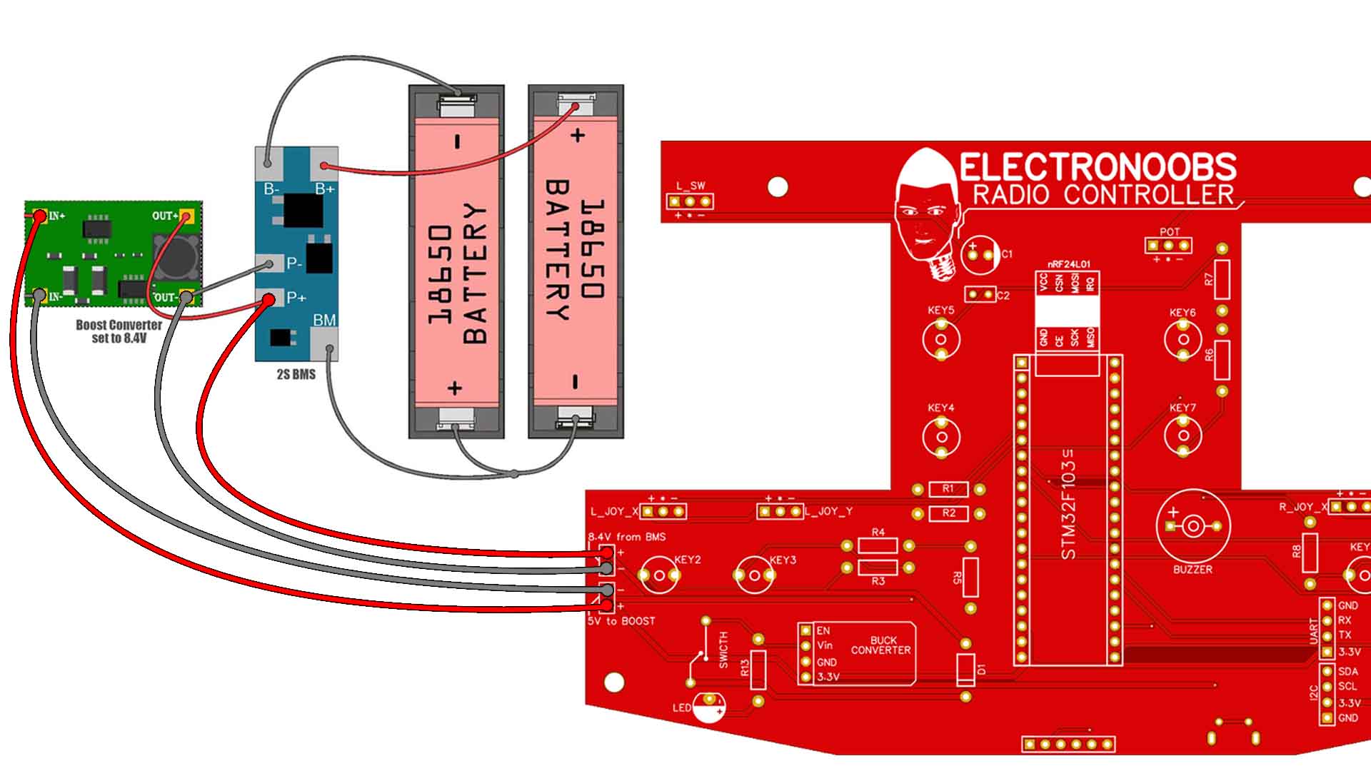
The PCB you will get is a bit different than the one in the photos since I've made some changes. Ok, first get the small Boost Converter and solder the 3.3V connection on the back so its output will be 3.3V. Check the value with the multimeter. Then solder it to the PCB. Then solder the rest. THe STM32, the NRF24, the connectors for the display and so on. We won't use the push buttons for now but maybe solder those as well. Solder the main on and off switch and the LED + Buzzer.
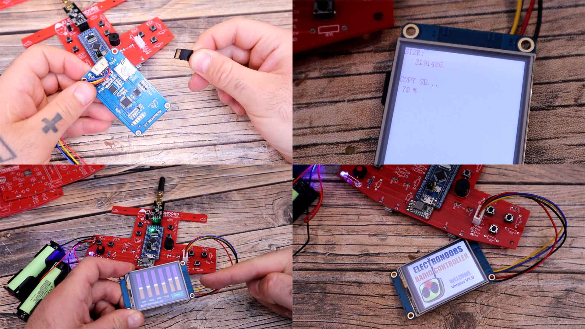
Finally connect the joysticks, the toggle switches and the battery circuit. Also connect the TFT NEXTION display to the UART pins. See below the TFT file and how to uplaod it tio the screen. Then all you have to do is to uplod the main code to the STM32 and fit everything inside the 3D printed case.
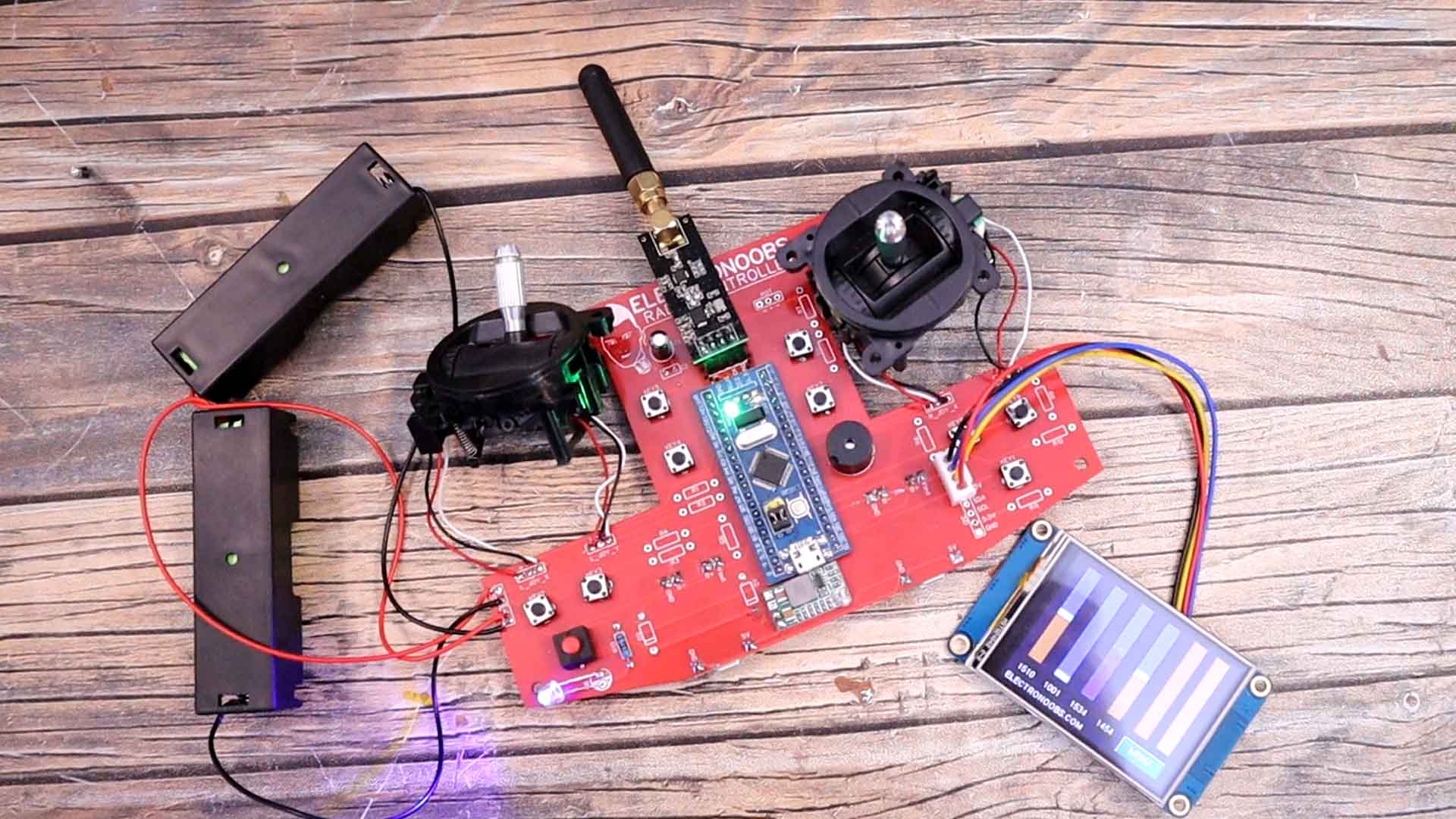
Download from below the TFT file. Extract the ZIP file and copy that TFT file to a micro-SD card. Then insert the card into the NETION display and turn it on. The TFT file will get copied to the memory. Then turn the display off and remove the SD card. Now when you power it back on it will have the graphics for all the channels and also a small animation at the beginning. The sliders might be jumping around if the joysticks are not connected. Now the screen is also ready.
Now in the code, another improvement is the precision. The STM32 makes the analog read with a 12-bits ADC in compare with the previous project with the Arduino that has only 10-bits ADC. With 12 bits we can read from 0 to 4095 so we need to send two bytes for each channel. Instead of a byte structure I’ve used long variables that will occupy 4 bytes. So we read the potentiometers, we send the data via serial for the display and we also send the data with the radio connection.
struct MyData {
  long throttle;
  long yaw;
  long roll;
  long pitch;
  bool AUX1;            //This is a digital channel (1000 or 2000), so we don't need precision
  bool AUX2;
};To test the received signal I get my NRF24 tester taht is made with an Arduino. This will print on the screen the throttle and yaw channels and also control an LED with a PWM signal according to the throttle channel. I've also connected that pin to my oscilloscope and see the signal, and it works. Uplaod the code below and make sure you ahve the same pipeIn value and change the CE and CSN pins for the Arduino NANO as in the schematic below.
const uint64_t pipeIn = 0xE8E8F0F0E1LL; //Remember that this code is the same as in the transmitter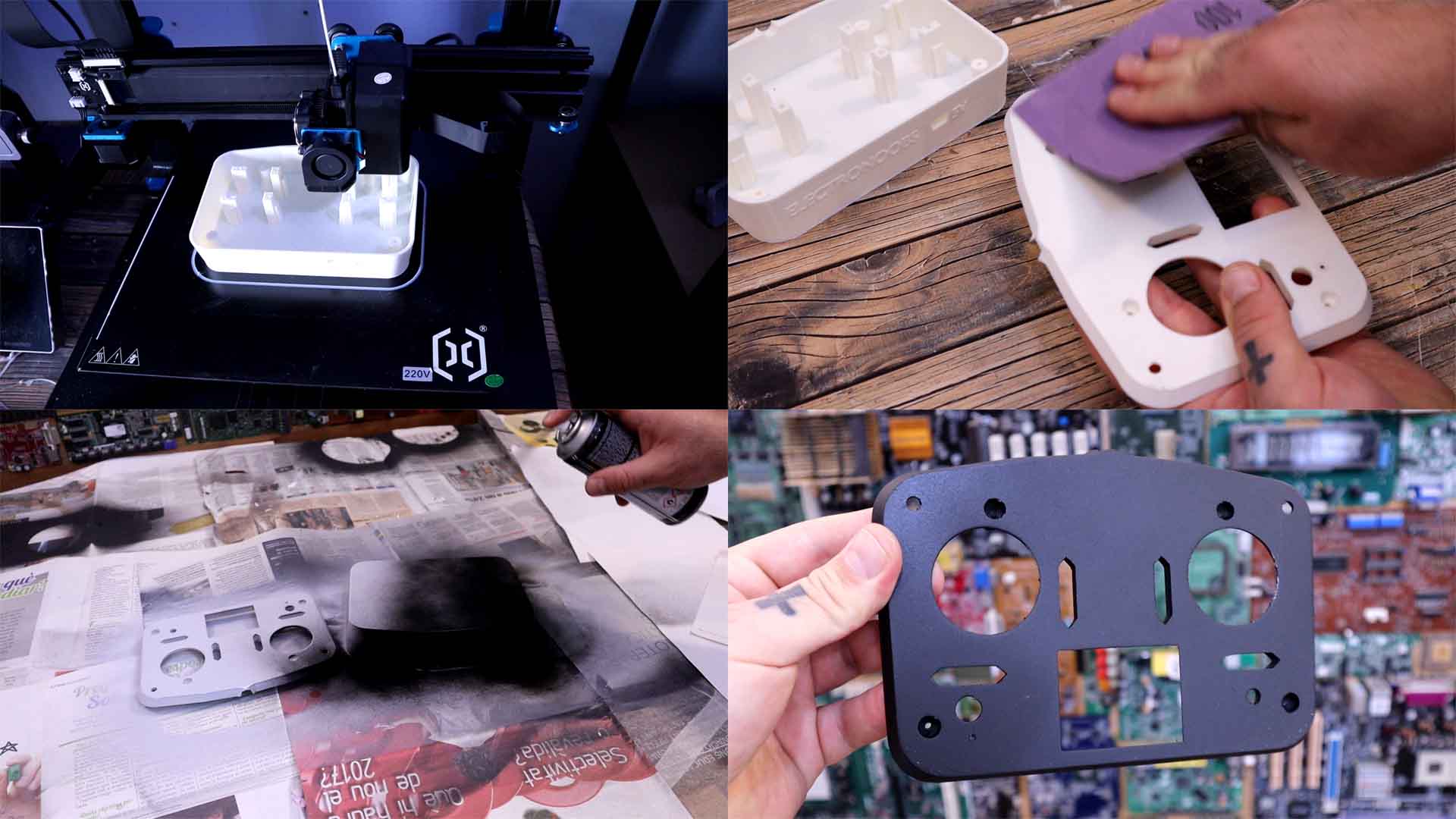
RF24 radio(9, 10); //CE and CSN pins (Arduino NANO)Print the case with PLA and 0.2mm layer height, 2 perimeters and 20% infill and no supports! Ok, we need to paint the case a little bit since white doesn’t look that good. So, we sandpaper it a bit. I first applied a coat of primer. After a few hours I’ve sandpapered the case again and then I’ve used some spray paint and paint it black. If needed we can apply more than one coat of paint. I've also painted the buttons with a gold color.
Before I assemble it we need to add some brass insertion threads. So get them and your soldering iron. Heat them up and push the nut inside the plastic case. Now we can use M3 nuts to close the case. I glue the battery sockets in place with some double side tape. On top I put the PCB. Right after that, I add the joysticks in place and add two screws. Before we close the case, we need to add the small top buttons. I secure in place the NEXTION display with some hot glue for now. Then, I add all the buttons and secure them in place with some elastic ribbons. The top case is made in such a way that it will sandwich the PCB in between the top and bottom case. So now I close the case.
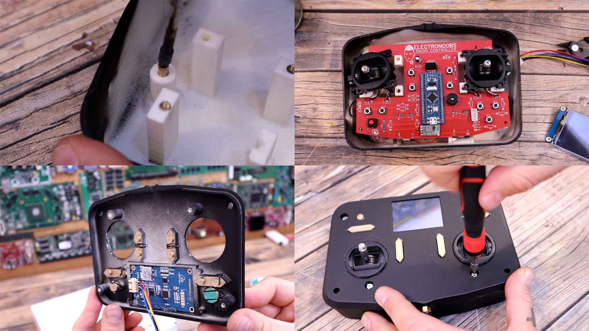
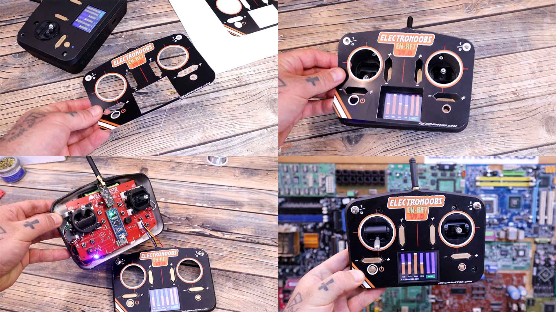
And that’s it, the controller is ready. Just one more step. I've designed this front label and printed it on a thin cardboard. I cut the shape and now I will glue it on top of the case to give it a better look. I also add the toggle switches. I think it looks quite good, right?
The idea is that on a future video I will also finish the receiver PCB and this has outputs for 7 channels and a PPM pin as well. In that way it would be like any other commercial controller. Please stay tuned for more updates on this project and more tests for speed, precision, errors that might appear and so on. If my videos help you, consider supporting my work on my PATREON or a donation on my PayPal. Thanks again and see you later guys.