
This tutorial will be the first part of my Arduino based open source DLP resin printer. This project will have more than one part because is quite complex and I don’t have the body of the printer yet. All I have is the electronics part which is working quite good for now. But as you know, a printer is made of electronics part and mechanical part such as the lead screw, the resin bath, the printing platform and so on, and I don’t have that part yet. What I have for now is the transparent LCD control for creating the mask, the UV light control for solidifying each layer, the SD card read process so we can take each layer mask in an BMP format and the step motor control for increasing the heigh of the print and homing the machine.
We have 3 basic parts. Part one, we have the resin. This resin is sensible to UV light and it will solidify when is touched by that light. The part two is the LCD mask. A display would create a mask with the shape that we want to solidify. So the light will pass and touch the resin only where the LCD is not dark. In that way we create the shape for our solid object. Part 3 is the layering process. We solidify a layer and we then go up using a step motor. The picture on the screen changes to the next and we solidify the next layer and so on, till we create the entire object. The resolution of the print is given by the layer heigh movement and the pixel resolution of the LCD screen, so obviously, the more and smaller pixels we have, the better the print quality.
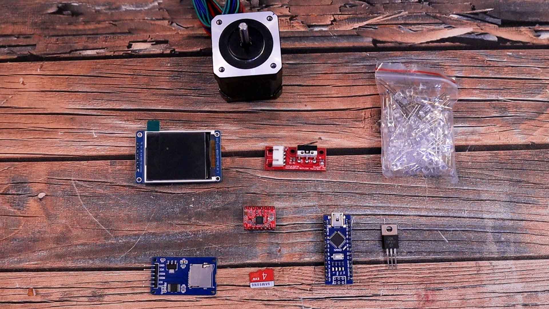
So we need to create these 3 steps. I need an LCD that could be made "transparent" to create the maks using BMP pictures. I need a step motor driver and a stepper motor to control the height of the printing platform. I need some UV LEDs to solidify the resin. The printer also needs an end switch to detect the 0 position.
Let me show you what components I’ve selected and how to use each one. To read the microSD card I have a small SD card reader module that communicates with SPI communication. For the LCD I’ve used this one based on the ST 77 35 driver. It has a resolution of 128 by 160 pixels and a diagonal size of 1.8 inches. We will need to hack this LCD and we will see how later. For the movement I’m using a NEMA 17 stepper motor controlled with a driver, the A4988 or maybe the TMC version from Trynamic for silent movement. For the LEDs, I’ve just ordered some UV LEDs and placed them in a matrix all in parallel. To control the power applied to the LEDs, I can use a BJT transistor controlled with an Arduino pin and that’s it for the light source. To detect the home position, we need an end switch like this one connected to the Arduino and that will stop the homing process when is pressed.
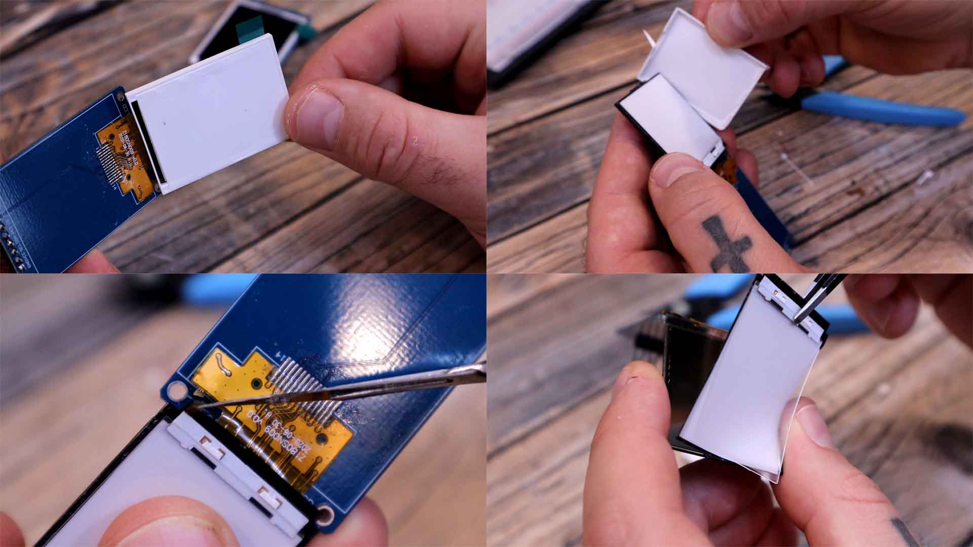
For the LCD I’ve used this one based on the ST 77 35 driver. It has a resolution of 128 by 160 pixels and a diagonal size of 1.8 inches. The screen is placed over a PCB that we don’t need. So carefully, remove the screen from the PCB. Then, we also need to remove the white plastic case, because we need to only have the screen and nothing more. Be very careful and have patient with this process. You have to cut a small wire here because that’s the backlight and we don’t need it. Then we can remove the backlight layers and we get only the screen. When you remove the plastic case, you will see all sort of layers coming out. Don’t worry, we don’t need these. These layers are fore the backlight.
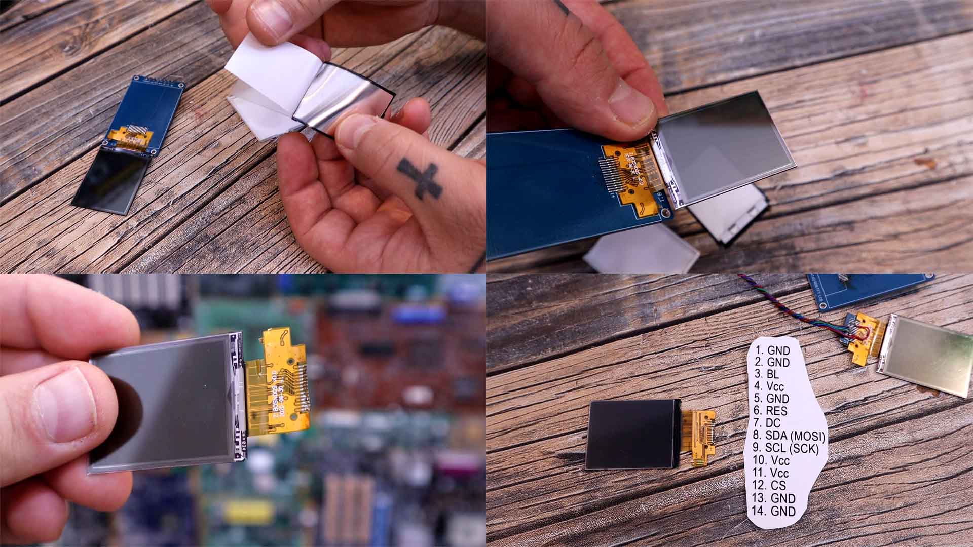
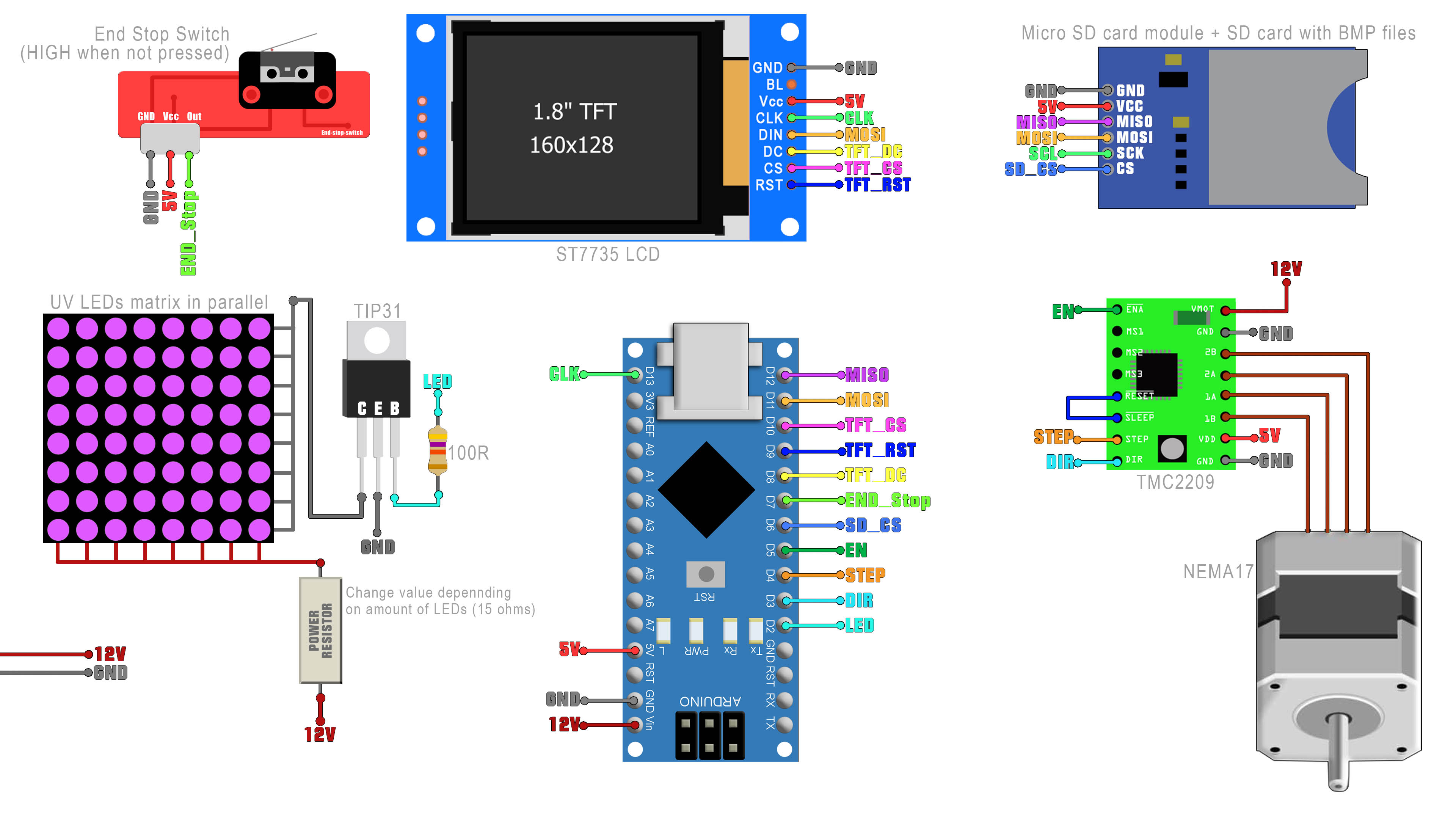
Finally we end up with this below, only the screen with the polarizing pixels and that’s all we need to create the mask. You can also de-solder the screen from its PCB and below you have the pinout of the strip connector if you want to solder it directly with wires or to a PCB. My plan is to make my own PCB for the printer and solder this directly to that PCB. Below you have the Arduino connections and the ST 77 35 library and an example file. With that code, all we have to do is to use the bmpDraw function and select the name of the file on the SD card.
You have all the connections below. The SD card module and LCD screen are using SPI pins so they share the SCK and MOSI pins. The rest of the pins are defined in the code for the CS and so on. For the LED matrix I had 20 LEDs in paralel. You could limit the current with a few 1/4W resistors or with just one power resitor of 5W. It should limit the current to about 1A since each LED would use around 50mA. To turn the LEDs on and off I have the TIP31 BJT transistor controlled with pin D2 from the Arduino. The Step drivver could be the A4988 but is better to use the silent one the TMC2209. The entire circuit can be powered with 12V since the NANO has a 5V regulator so connect 12V to the Vin pin of the Arduino, to VMOT pin of the driver and to the LED matrix. Make the connections and then go to the enxt part and get the code and libraries.
Make all the connections as in the previous part of the schematic. Download the code and libraries ferom below. To install the library, download the .zip file below, open Arduino IDE and go to Sketch, include library, add .zip library and open the .zip file that you have just downloaded. Now the ST7735 and Adafruit GFX library sould be installed. Open the main Arduino DLP firmware code. Compile and check for errors and uplaod it to the Arduino NANO. Now the printer is ready to go. When you power up the printer at 12V it will start the printing process automatically since it has no buttons. So make sure you already have prepared the bmp files on the SD card and see how to make that process in the next step.
#define TFT_RST  9            // Reset line for TFT
#define TFT_CS   10           // Chip select line for TFT display
#define TFT_DC   8            // Data/command line for TFT
#define SD_CS    6            // Chip select line for SD card
//D11 -> MOSI SD + SDA TFT    //Connect D11 to MOSI of SD card module but also to DIN of TFT
//D12 -> MISO SD              //Connect D12 to MISO of SD card module
//D13 -> SCK SD + SCL TFT     //SCK is connected to SCK of SD module and TFT display
#define end_stop 7            //Out pin from the end stop switch
#define mot_en   5            //Enable pin of the TMC2209 driver
#define mot_step 4            //Step pin of the TMC2209 driver
#define mot_dir  3            //Direction pin of the TMC2209 driver
#define LED 2 //Pin connected to the abse of the TIP31 transistorDownlaod the zip file from below. It only has a few example bmp files with the resolution of the screen of 160 by 128 pixels. Extract the zip file and copy the bmp files directly to the SD card without any other folder. Insert the SD card into the module and power up the circuit. See the results.
As for the case, I’m working on some 3D designs. For the bath, I’m pretty sure the first prototype will be made out of acrylic and on the bottom layer we must add a FEP film that is used with resin printer. For the printing bed I will cut some sort of aluminum block and to level it I will probably use some kind of ball head because is very cheap. For the z axis I could use some smooth rods or maybe a sliding rod ike this one. So stay tuned for the next tutorial where I will have the mechanical part as well and not just the electronics.
But for now, I’m happy that the system works and looks quite promising. I can’t wait to print something with my own DLP 3D printer. Since I've started making tests for this project, I've ordered different TFT screens to test with, so maybe I will be able to make the next version a bit bigger. Also stay tuned for a PCB for the entire printer so it can be more compact and better looking. I hope you like this tutorial and maybe you have learned something new. If my videos help you, consider supporting my work on my PATREON or a donation on my PayPal. Thanks again and see you later guys.


