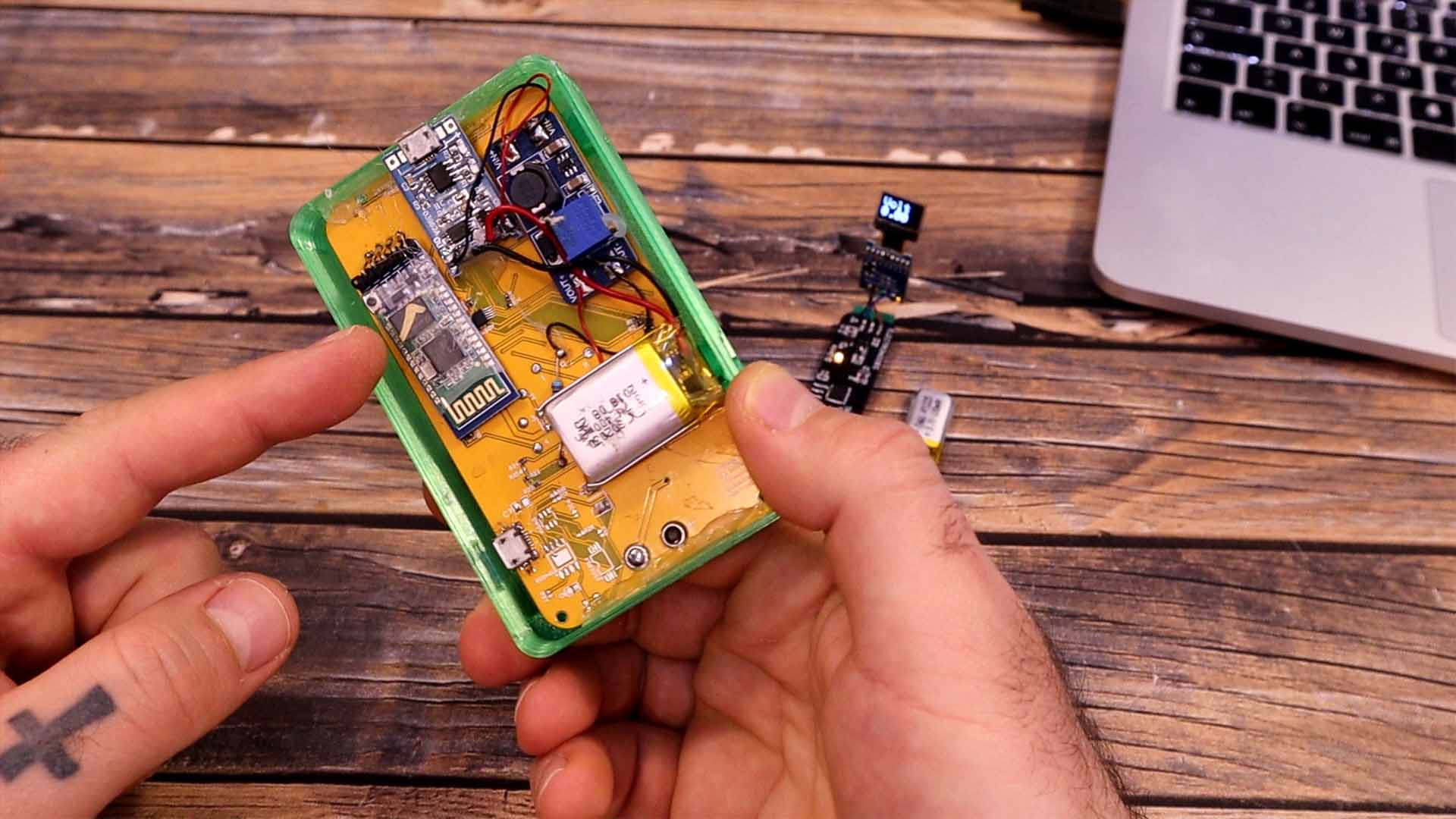
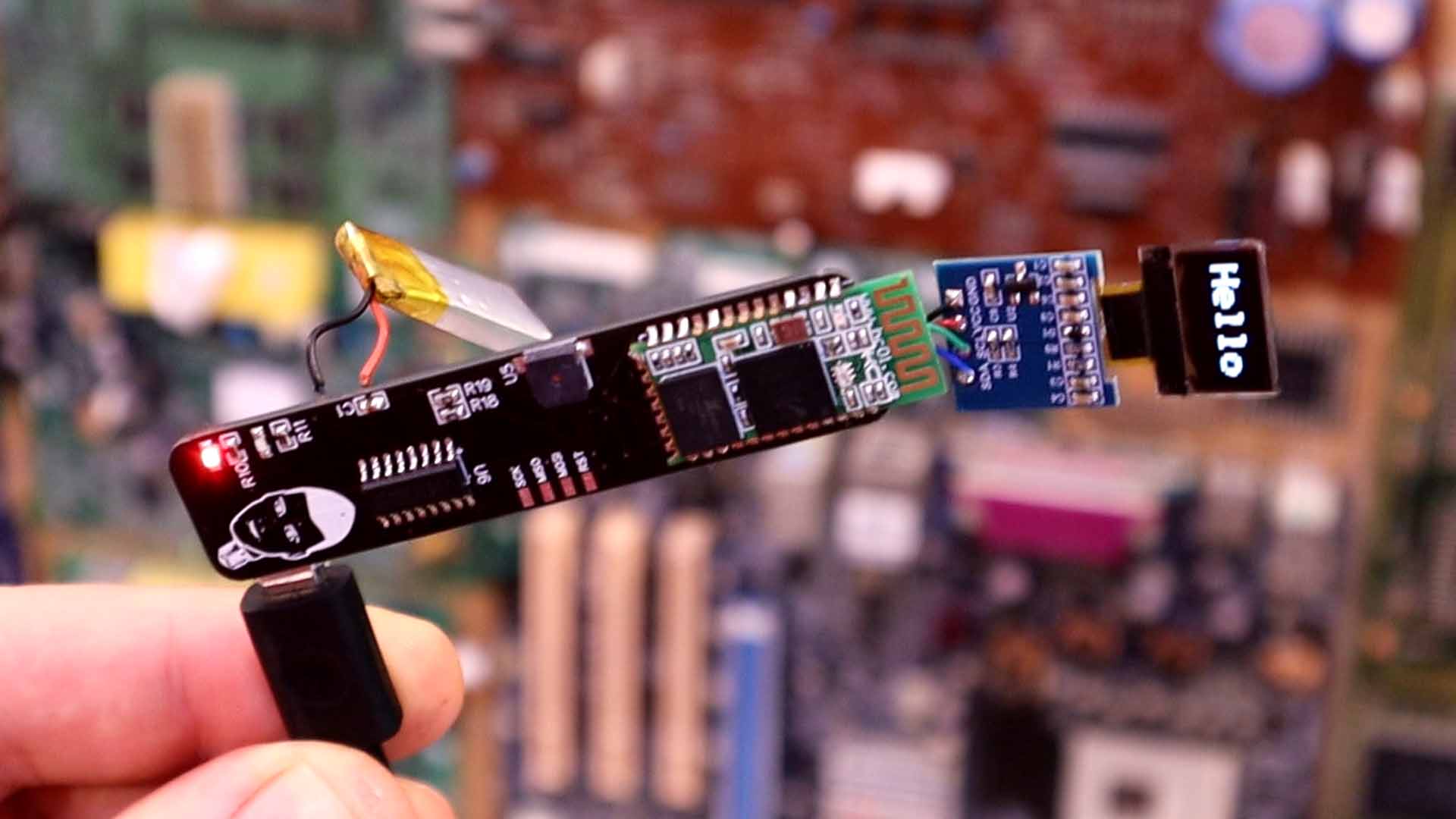
This is my first version of a smart-glasses multimeter. Is not the most unique and best look design, but this is yet a first version. I’m pretty sure I will improve it in the future. Anyway, inside the 3D printed case, we have a custom-made PCB that I will show you later, a Bluetooth module, a small LiPo battery and a very small OLED display. The difficult part was to get the text from the OLED display to focus near the eye, and for that the solution was to place the screen at the far back of the case, then use a lens to make the text bigger and then project it towards the eye. So, I will show you the PCB that I’ve made, the problems I had, show you what components we need and how to solder each one and in which order, then we make some tests and show you some results. This project is made to work together with an old project of the Arduino multimeter. If you remember, that project had a Bluetooth output, so all I need to do is to send the Bluetooth data from that multimeter to my glasses and show the value on the tiny OLED screen. I’ve used a small MSOFET connected to the Bluetooth module, so we could turn the module on and off whenever we want.
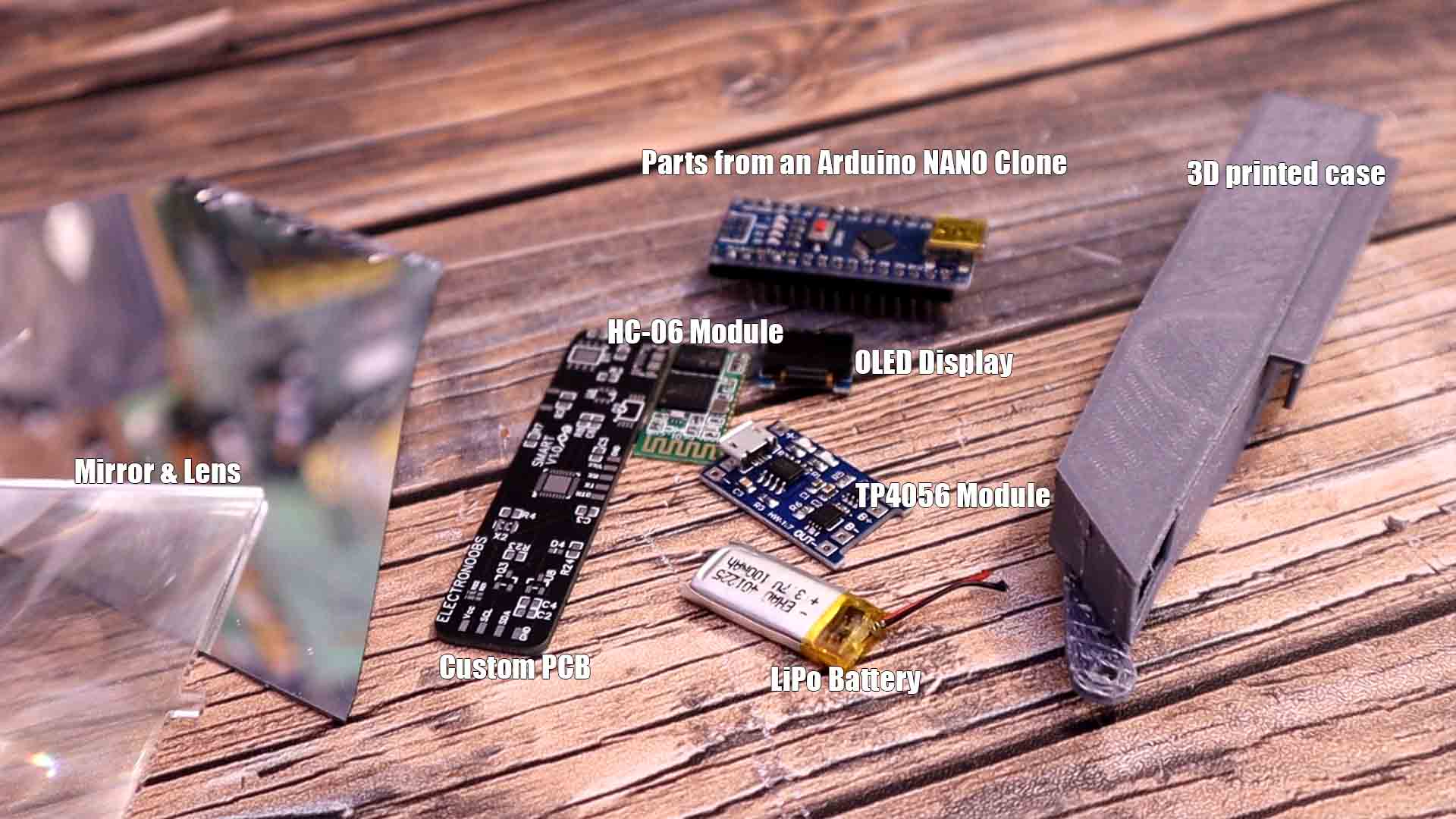
Ok, let me show you the parts we need. You will need the PCB, of course, the HC06 Bluetooth module in the SMD version, the small OLED display of 0.46", a small LiPo battery of 100mAh and for the charging circuit, you can take all the components ouf of a TP4056 module. The ICs, the resistos and capacitors and even the USB connector could be used from a module if you don't want to buy all the components separately. Then, for the ATmega328 module, you could take it out from an Arduino NANO clone, in that way you make sure it works and t has a bootloader. Make sure the Arduino clonse is using a QFN package for the ATMega chip. In the same way, you could also desolder the CH340 IC from the back and solder it to you PCB. Together with these components you will need my design of the case so downlaod it and print it out with PLA material. You will also nee some sort of mirror and a plastic fresnell lens. You can buy those for cheap from the internet. All links are below in the part list. So, this is all we need. I've took the small ressitors, the capacitors and the 16Mhz crystal from the Arduino clone. If you want, you can buy all those separately from the links below.
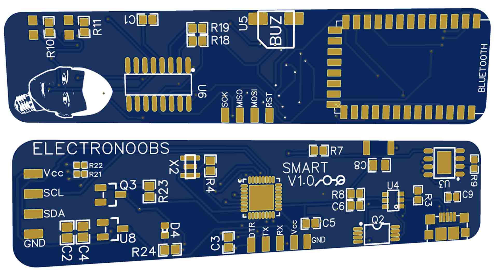
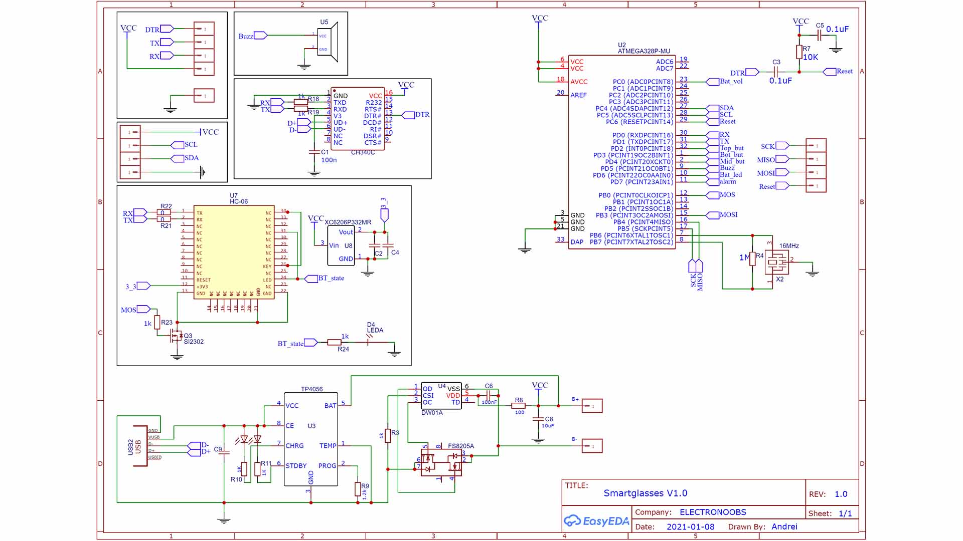
On this PCB we have, the ATmega328 microcontroller, the TP4056 charging IC because this will be portable so it needs a battery. As input, I have a micro-B USB connector. Then we have two sets of pads. Ones are for the OLED display i2c communication and these other pads are for the UART port. And on the back, we have a buzzer for sound notifications and an FTDI programmer, the CH340, so we could program the board with the USB cable. We also have pads for an HC-06 Bluetooth module. And that’s it. I’ve made my schematic and this below is the final version. But I forgot to add a switch, so this PCB would be always on if the battery is connected. I’ll add the switch for the future version. I pass to PCB and decide where to place each component and I try to make the PCB as small as possible.
The PCB design is ready and looks quite good. So I download the GERBER file and go to PCBWAY.com which is the sponsor of my project. I select quote now., and by the way, if you create a new account, you get a 5 dollars coupon. I insert the width and height of my PCB and select a quantity of 10 PCBs which will cost me only 5 dollars plus shipping. I leave it at 2 layers and I select a black solder-mask. I click calculate. I select shipping to Spain and an e-packet shipping method. Then I save to cart. Here I click the “add gerber” button and select the GERBER file I’ve previously downloaded and you have that .zip file below. Once uploaded I click submit order and in just a few days I receive my PCBs from PCBWAY. I make a quick inspection and they all look quite well.
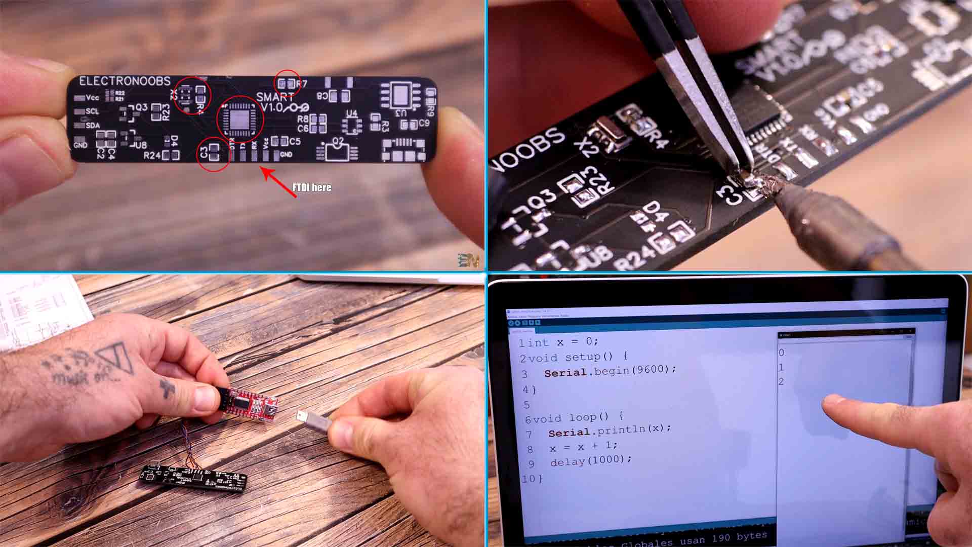
Is time to solder all the components but you must follow an order. First, solder the ATMEAG328 microcontroller, the R7 resistor, the crystal clock and the R4 resistor, and the C3 DTR capacitor of 100nF. You have all these values on the schematic above. This is the basic configuration of the ATMEGA chip, so once soldered, connect and external FTDI programmer to the UART port pads. Then upload a test sketch and see if it works, see example code below. I usually upload a counter so when I open the serial monitor, I should see the counter value. That means the IC works so we can solder the rest.
int x = 0;
void setup() {
  Serial.begin(9600);
}

void loop() {
  Serial.println(x);
  x++;
  delay(1000);
}
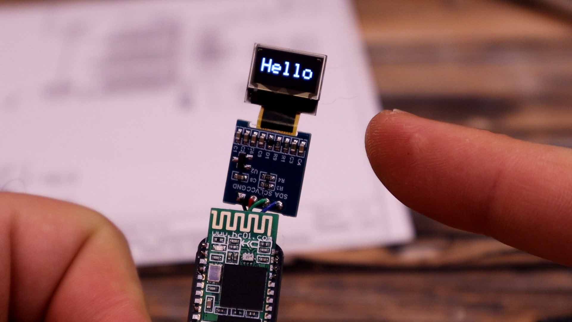
Once we have all the components, since I now have the FTDI programmer in place, I could upload the code directly with the USB cable without using the external programmer. And on the i2c pads, I solder the tiny OLED screen with some thin wires. I upload a test code and as you can see below the OELD display works but we also need the Bluetooth connection. You must use an HC-05 to send the data because the HC-06 can only work in slave mode.
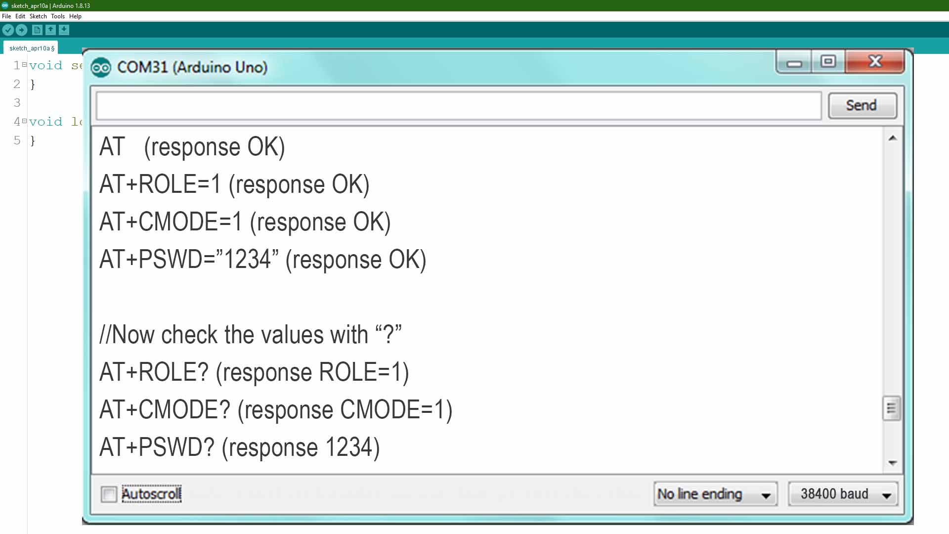
To make a connection between the HC-05 and the HC-05 you have two options. Make the HC-05 connect to any module that it finds around, or make it connect to a specific module. I select the first option because is easier and faster. Upload an empty sketch to the Arduino first. We need to set the HC-05 module as master. For that make the connections below between the module and the Arduino. Power on the HC.05 module while pressing the enable button you have on the tiny PCB of the module and you will se the LED blinking long. That means we are into AT mode. Then open the serial monitor in the Arduino IDE. Select the baud rate of 38400. Type AT and press enter. If you get an OK response, we are good to go.
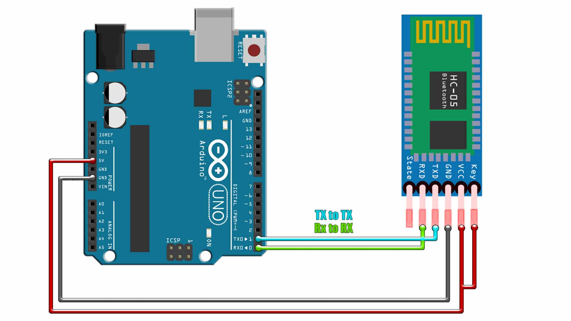
First type AT+ROLE=1, in order to set the HC-05 module to be a master. You should get an OK response. Then type AT+CMODE=1, so we make the HC-05 module to connect to any other Bluetooth module it finds around, in this case, the HC-06 module we have on our PCB. The master Bluetooth is ready. Just make sure the password of the HC-06 is the same as the password of the HC-05, which usually is 1234. If not, you can type AT+PSWD="1234" and press enter. And to check if that’s correct, type AT+PSWD? and press enter and you should get the response 1234.
Ok, I now upload a code to my Arduino and send the data from the potentiometer using the Serial.print function. I power on both parts and wait a few seconds. The LED of the module will stop blinking so the connection is made. And as you can see, I now get the data from the potentiometer to my small OLED screen. Remember to change back the RX and TX wires to RX-TX and TX-RX from the HC05 to the Arduino. We only had RX-RX and TX-TX for the AT mode.
int pot = A0;
void setup() {
  pinMode(pot, INPUT);
  Serial.begin(9600);
}

void loop() {
  float val = map(analogRead(pot),0, 1024, 0, 500);
  val = val/100;          //Calculate voltage value from 0.0 to 5.0 volts
  Serial.print("V");      //First we print "V" for voltage
  Serial.println(val);    //Then the value from the potentiometer
  delay(100);             //Small delay
}#include <SPI.h>
#include <Wire.h>
#include <Adafruit_GFX.h> //download here: https://www.electronoobs.com/eng_arduino_Adafruit_GFX.php
#include <Adafruit_SSD1306.h> //downlaod here: https://www.electronoobs.com/eng_arduino_Adafruit_SSD1306.php
#define OLED_RESET 5
Adafruit_SSD1306 display(OLED_RESET);
int BT = 8; //Pin connected to the Bluetooth Mosfet
void setup() {
Serial.begin(9600);
pinMode(BT,OUTPUT);
digitalWrite(BT,HIGH); //Turn on the Bluetooth MOSFET
display.begin(SSD1306_SWITCHCAPVCC, 0x3C); // initialize with the I2C addr 0x3C (for the 32x32 from eBay)
delay(100);
display.clearDisplay();
display.setTextSize(2);
display.setTextColor(WHITE);
display.display();
delay(100);
}
void loop() {
if(Serial.available() > 0){
char type = Serial.read();
if(type == 'V'){ //Detect if we receive volts
float volt = Serial.parseFloat(); //Get the received value
display.clearDisplay(); //Clean previous screen
display.setCursor(32,32); //X / Y
display.print(" Volt"); //Print "volts" tag
display.setCursor(32,48); //X / Y
display.print(volt); //Print the received value
display.display(); //Display everything
}
}
}
I can do the same with my old project of the multimeter. Remember it had this UART port on the back for a Bluetooth module. I solder the HC-05 module there and upload a new code. By the way, all the codes for these projects are below. This new code will use
Solder the HC05 module to the multimeter PCB. Go below and get the new version of the Multimeter code. Make sure you also check my old project of the multimeter. This new code will still print the values on the OLED display but also send the same data with Bluetooth connection. All we have to do is to get the receiver code and upload it to the smart glasses PCB and receive the data. So once you uplaod the multimeter code from below, go and see the receiver code.
Get the full code from below. You would need the OLED libraries as well. You will see that the first thing thew code dose is to power up D8, which is the pin connected to the Bluetooth module MOSFET, so now the HC06 is powered on. Then we start the OLED display and prine hello. In the void loop we check for a serial communication. If we receive something from the Bluetooth moduel, we first check if is a "V" a "A" a "R" and so on, in order to detect if we receive values for voltage, current, resistance and so on. Then we use the Serial.parseFloat() function to get the numeric value. This fucntion will automatically separate the float number from the text values that we receive. That's it, next we print the value on the tiny OLED screen.
if(Serial.available() > 0){                   //Detect if we receive something
    char type = Serial.read();                  //If we receive a "V" then the value is for voltage.
    if(type == 'V'){
      float volt = Serial.parseFloat();         //Using parseFloat we get only the float value after the "V"
      display.clearDisplay();
      display.setCursor(32,32);        //X / Y
      display.print(" Volt");
      display.setCursor(32,48);        //X / Y
      if(volt < 0 ){
          volt = volt * -1;
      }
      display.print(volt);
      display.display();
    }
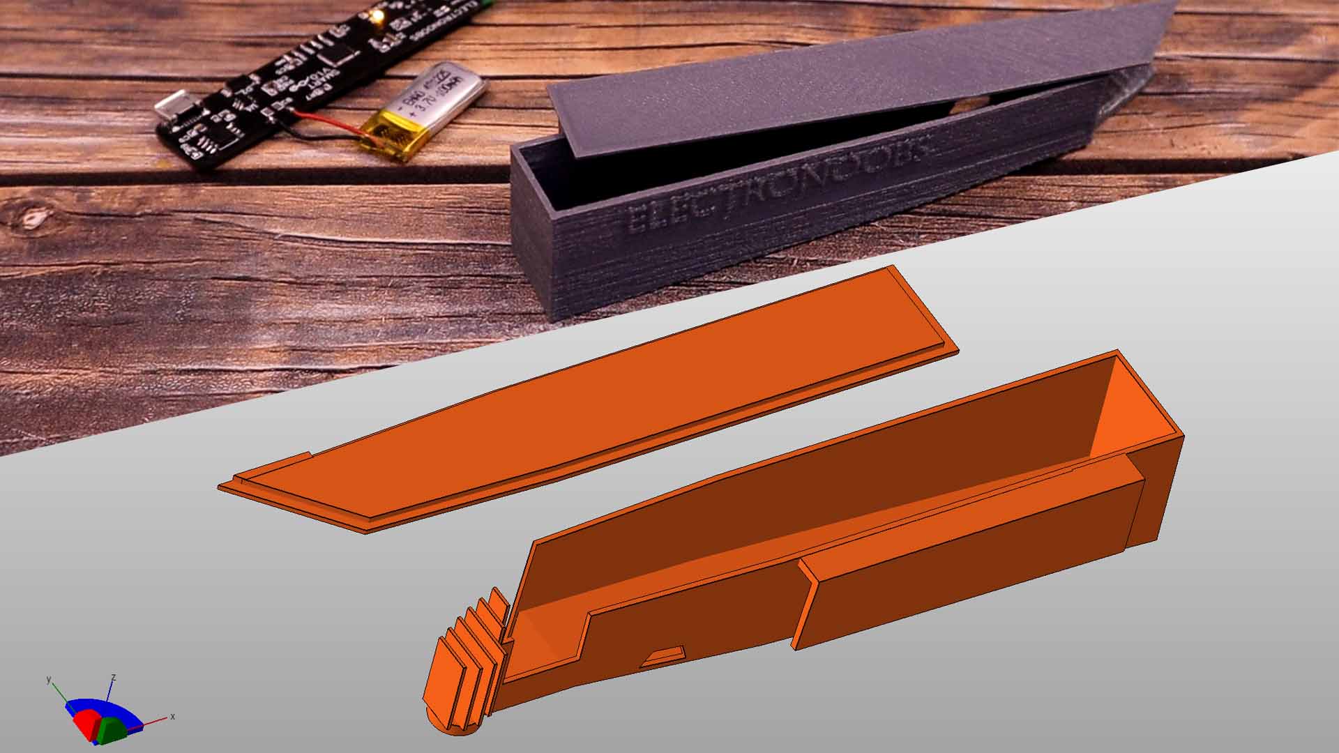
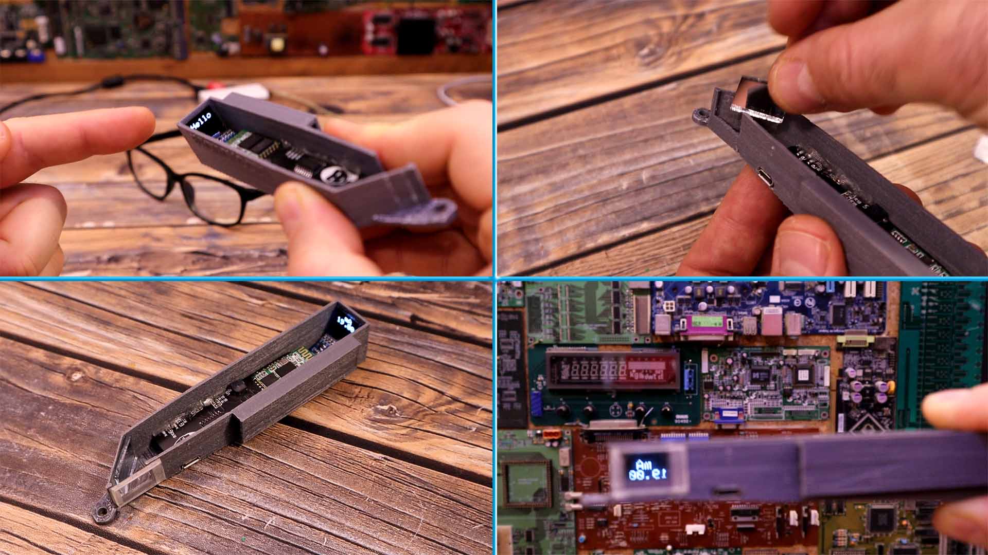
Is time to make a case. I first made some tests with a cardboard box. You see, the easiest way would be to solder the screen just in front of your eye. But in that way, is impossible for our eyes to focus that close. That’s why we need to place the screen far away. But then the picture would be too small. I’ve design and 3D printed a case for this project, which I’m pretty sure I could improve a bit. So this case will have the screen on the far back, a mirror on the front at 45º angle and then a small Fresnell lens and finally a plexiglass in front of you eye. In that way the picture is enlarged and pointed towards your glasses. The case could attatch to the frame of those glasses.
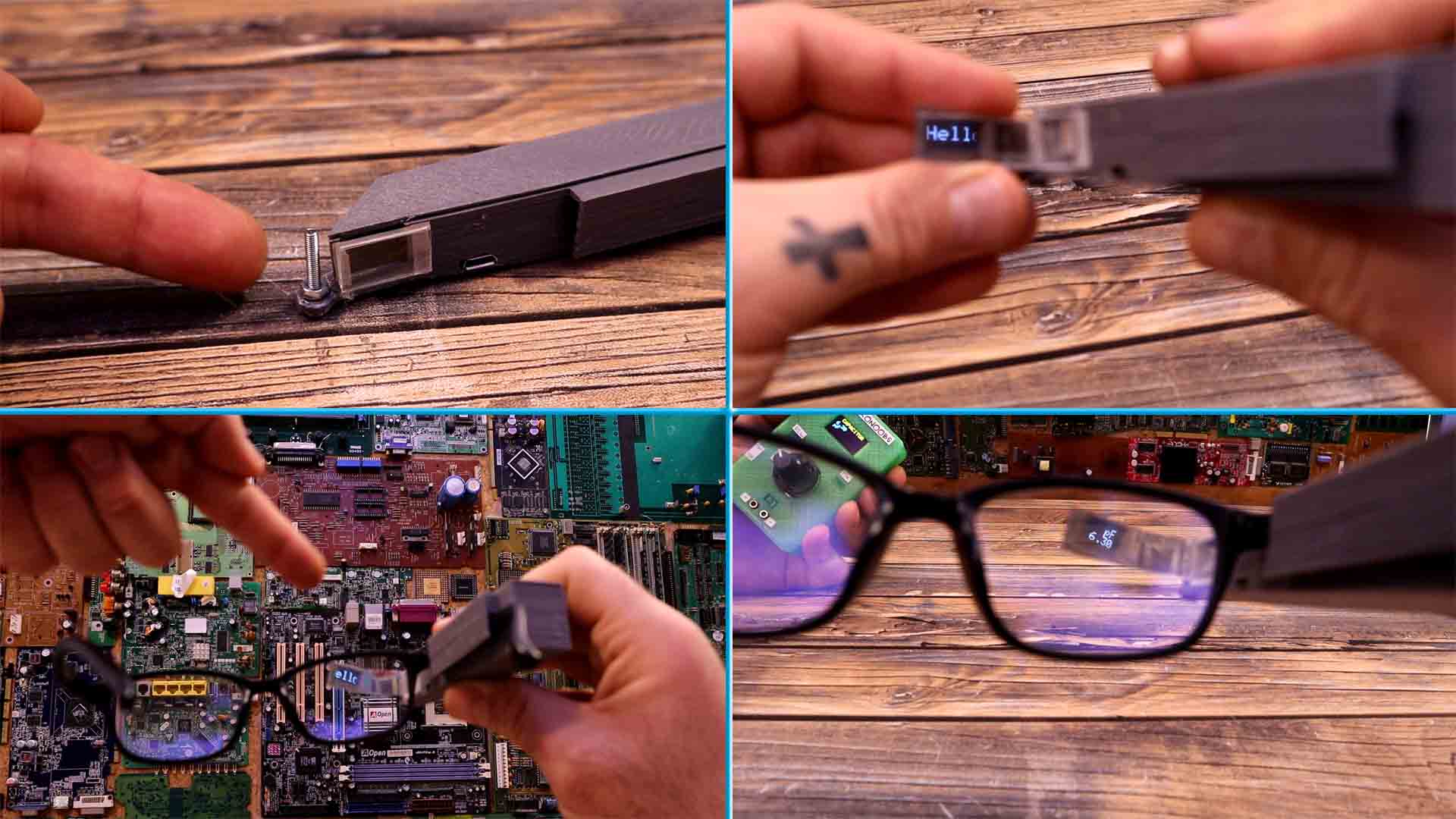
I place the PCB inside and check If I can connect the USB connector. I add double side tape on the far back of the case and I glue the small screen. Then I also add some double side tape where the mirror will go. I cut a small rectangle of mirror. I glue that mirror with 45 degrees angle and as you can see, we now have the picture from the screen. At the output, I cut a small Fresnell lens and glue it in place as well. I now close the top part of the case and as you can see below, we have the picture from the screen at the output. Pretty nice, right?
I add a small screw at the tip of the case. On this screw I glue a small pelxiglass that will reflect that light from the OLED display towards our eyes. And this project is complete. Place the case over your glasses and adjust the reflection glass so you can see the screen inside. Turn on the multimeter and wait for it to connect. Select the mode, for example capacitance and measure a capacitor. And there you go, we have the value on our smart glasses.
I will have to make a smaller version of the multimeter that could be used with two hands and having the PCB in one side and the positive probe on the other. In this way this project would be very easy to use. I hope you like this tutorial and maybe you have learned something new. If my videos help you, consider supporting my work on my PATREON or a donation on my PayPal. Thanks again and see you later guys.