This device can measure anything, anything. Even the flatness of the earth. Naah guys, just kidding. But I think this will finally get to be the best multimeter for makers and small electronics projects. This is my new version of the two/hand multimeter made with Arduino capable of measuring all these units and more to come because is getting better by the day… I was tired of trying all types of sliders and switches, and I decided to make my own
by: ELECTRONOOBS on 2026-06-28
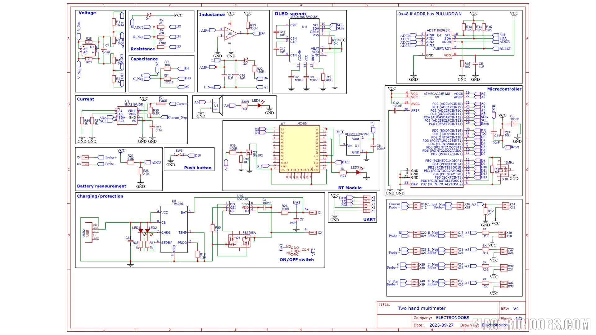
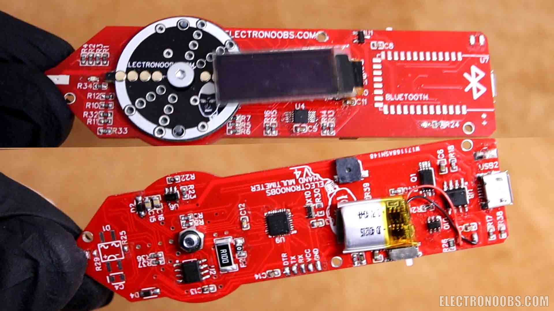
Another difference from my previous versions, is the use of a different chip for measuring current. For my previous versions I was using a hall effect module and that’s not very reliable, especially for switching signals. This time I’m using a shunt module with the INA219 IC and is capable of measuring current and power. The board also has Bluetooth so we can send the values to a smartphone App, and that’s very interesting. It uses the ADS1115 ADC so we have plenty of precision with a 16 bits ADC. It also has a charging circuit so we can charge the battery with a USB cable. I won’t go over the full schematic because I’ve already done that for my previous versions and the rest is quite the same. Except this part here with all the pads representing each connection for the dial for each mode.
Let’s start with the part list. Well, you will need the 3D printed enclosure. So get the 3D files from below and print them. I've used a resin printer. You also need my designs for the PCBs so you could order them from PCBWay. The rest are electronics components such as the ADC, the ATmega328 chip, OPAMPs, resistors and capacitors. Check the values on the scheamtic.
- 3D case: From Below
- PCB GERBERs: From Below
- 1 x ATMega328p MU: LINK Aliexpress
- 1 x 3213 16MHz resonator: LINK Aliexpress
- 1 x ADS1115IDGSR (take out from module): LINK Aliexpress
- 1 x SSD1306 SMD 32" screen: LINK Aliexpress
- 1 x INA219AIDR + Shunt (take out from module): LINK Aliexpress
- 1 x LMC7101AIM5X/NOPB: LINK Aliexpress
- 1 x TP4056 (take out from module): LINK Aliexpress
- 1 x DW01A (take out from module): LINK Aliexpress
- 1 x FS8205A (take out from module): LINK Aliexpress
- 1 x HC-06/05 SMD Bluetooth: LINK Aliexpress
- 8 x Springy 2.54 pins 6mm: LINK Aliexpress
- 1 x SMD Push button: LINK Aliexpress
- 1 x XC6206P332MR 3.3V Regulator: LINK Aliexpress
- 2 x FR104W Diode: LINK Aliexpress
- 0603 LEDs: LINK Aliexpress
- 0603 Resistors (check values on schematic): LINK Aliexpress
- 0603 Capacitors (check values on schematic): LINK Aliexpress
- 1 x Micro USB connector: LINK Aliexpress
- 1 x buzzer klj-5020: LINK Aliexpress
- 1 x 3.7V Battery: LINK Aliexpress
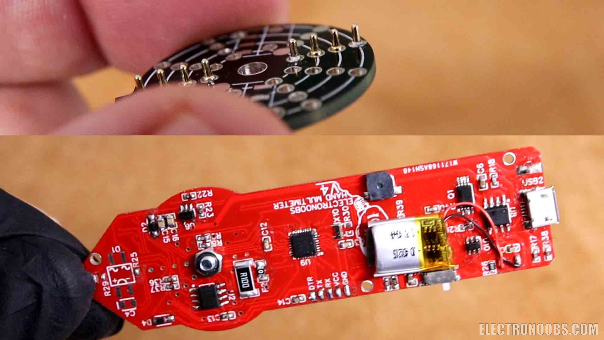
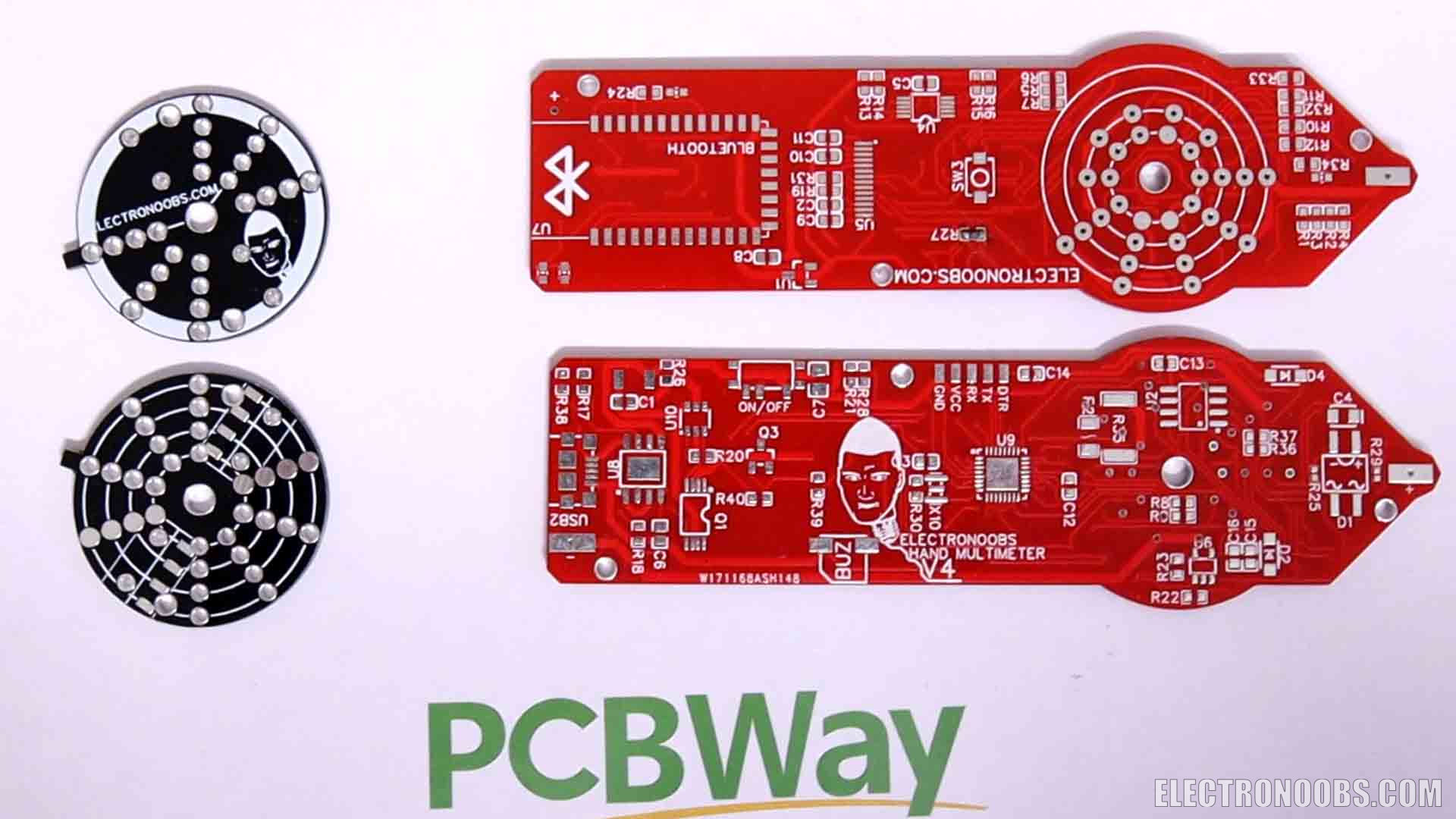
So if you want to make the same project you can download the GERBER files from below and check all the parts and schematics on electronoobs.com. Go to PCBWay.com and click the quote button. Here we add the size of the pcb and the amount. To get the 5 dollars offer, select 5 PCBs. For the color I went with red this time. Save to cart and here, on the next page, upload the GERBER files you've just downloaded from my website. Place the order and in just a few days, I receive some awesome PCBs from PCBWAY. Remember we need two PCBs for this project, the main multimeter and this dial which is just a circle. The reason it has multiple holes is because I wasn’t sure which type of pins I will use so I’ve placed a lot of them. Now that I’ve decided which to use, I will make the PCB with only one row of holes. The PCBs look awesome as always so we can start with the project.
So get the PCBs and download the schematic from below and I solder all the components. I’ve took the chip from an old Arduino nano clone. We start with the ATMEGA chip, resonator and pullups and then all the resistors, capacitors and the sensible ICs as the ADC, OPAMP and current meter. I won’t add the Bluetooth module yet. Once everything is in place, I add the dial on top with a screw. It will get better once I also add the enclosure that I’ve designed for this.
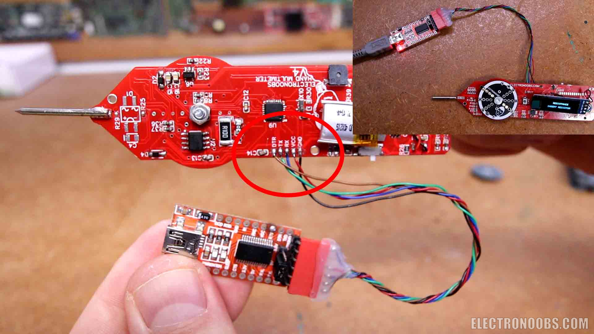
I connect this FTDI module to the UART pads and I open the code. Read it line by line to understand more but is still pretty much the same as for the previous versions. Detect the mode and inside each mode we use the formulas to measure each value. I recommend you to check my previous videos about the multimeter in order to understand how each block works. Compile and upload it to the multimeter. Now as you can see, by rotating the dial we can change between modes. Also, by pushing the button we change to the extra modes such as continuity, diode mode or frequency. When charging the red LED is turned on and when the battery is full, the blue LED will turn on.
/* Arduino Two Hand Multimeter V4.1 by ELECTRONOOBS (Voltage, resistance, capacitance, inductance, current, etc)
More info on: https://electronoobs.com/eng_arduino_tut194.php
Support on PATREON: https://www.patreon.com/ELECTRONOOBS
YouTube Channel: https://www.youtube.com/@ELECTRONOOBS
Video Here: https://youtu.be/lmUTQCBEtYU*/


/////////////////////////Library for INA219 CUrrent Module/////////////////////////////
#include <Wire.h>
#include <Adafruit_INA219.h>
Adafruit_INA219 ina219;
//////////////////////////////////////////////////////////////////////////////////////


/////////////////////////////Library for ADS1115 ADC//////////////////////////////////
#include <Adafruit_ADS1015.h>       //Download here: https://www.electronoobs.com/eng_arduino_Adafruit_ADS1015.php
Adafruit_ADS1115 ads(0x48);
//////////////////////////////////////////////////////////////////////////////////////

////////////////////////OLED 64x124 display with i2c//////////////////////////////////
//OLED screen libraries
#include <Adafruit_GFX.h>           //Download here: https://www.electronoobs.com/eng_arduino_Adafruit_GFX.php
#include <Adafruit_SSD1306.h>
#define OLED_RESET 11
Adafruit_SSD1306 display(OLED_RESET);
//////////////////////////////////////////////////////////////////////////////////////


//Define Inputs Outputs
int mode_selector = A3;           //My analog values were: 250, 800, 480, 336, 1024

//Voltage Mode
int VOLT_PIN_0 = 7;               //For voltage mode side of ADC0
int VOLT_PIN_1 = 12;              //For voltage mode side of ADC1

//Res Mode
int RES_PIN_2K = 8;               //Pin resistance mode for 2K divider
int RES_PIN_20K = 4;              //Pin resistance mode for 20K divider
int RES_PIN_470K = 5;             //Pin resistance mode for 470K divider

//Inductance Mode
int Induct_OUT = 6;               //Pin inductance mode to diode
int Induct_IN = 9;                //Pin inductance mode from OPAMP
int Induct_GND = A1;              //Pin inductance for GND simulate

//Cap Mode
int CapAnalogPin = A0;            //Pin for cap mode connected to Negative Probe
int CapAnalogPin2 = A2;           //Pin for cap mode connected to Positive Probe
int chargePin = 11;               //Pin for cap mode connected to 10K res
int dischargePin = 13;            //Pin for cap mode connected to 220R res

//BT module
int BT_MOS = A7;                  //Bluetooth module activation mosfer
int BT_RX = 2;                    //Bluetooth RX pin
int BT_TX = 3;                    //Bluetooth TX pin

//Extra
int Buzzer = A6;                  //Pin connected to an LED and buzzer
int Push_button = 10;             //Pin connected to the middle push button


/////////////////////Variables/////////////////////
int mode = 0;
int mode_prev = 0;
bool Push_button_state = true;
bool switch_once = false;

//Voltage mode
float VoltageReadOffset = 0.0;
float Voltage = 0.0;
float Volt_ref = 0;

//Resistance mode
float R2_1 = 2000;    //In ohms
float R2_2 = 20;    //In K ohms
float R2_3 = 470;     //in K ohms
int Res_Offset = 0;
int Continuity_Res_Offset = -2;
float D4_diode_ofset = 0.61;
bool conductivity = true;

//Capacitance mode
unsigned long startTime;
unsigned long elapsedTime;
float microFarads;
float nanoFarads;
#define resistorValue  10800.00F  //Remember, we've used a 10K resistor to charge the capacitor
bool cap_scale = false;
//Small scale
const float IN_STRAY_CAP_TO_GND = 56.88;
const float IN_CAP_TO_GND  = IN_STRAY_CAP_TO_GND;
const float R_PULLUP = 34.8;
const int MAX_ADC_VALUE = 1023;

//Inductance mode
double pulse, frequency, Induct_cap, inductance;

//Current mode
float Sensibility = 0.185;                      //Given by the ACS712 datasheet but tweeked a bit


//Frequency mode
unsigned long ontime;
unsigned long offtime;
unsigned long the_period;
float the_frequency;
float the_capacitance;


void setup() {
  Serial.begin(9600);
  pinMode(mode_selector, INPUT);
  pinMode(Push_button, INPUT_PULLUP);

  ads.setGain(GAIN_TWOTHIRDS);        //+/- 6.144V  1 bit = 0.1875mV (default)
  ads.begin();                        //Start the communication with the ADC

  if (!ina219.begin()) {
    Serial.println("Failed to find INA219 chip");
  }

  display.begin(SSD1306_SWITCHCAPVCC, 0x3C);  // initialize with the I2C addr 0x3C (for the 128x32 or 64 from eBay)
  delay(50);
  display.clearDisplay();             //Clean the buffer
  display.setRotation(2); //rotates text on OLED 1=90 degrees, 2=180 degrees
  display.setTextColor(WHITE);
  display.display();                  //Send data to screen

  delay(50);


  set_all_inputs();

  PCICR |= (1 << PCIE0);    //enable PCMSK0 scan
  PCMSK0 |= (1 << PCINT2);  //Set pin D10 trigger an interrupt on state change.
  mode_prev = mode;
}

void loop() {

  /////////////////////////////MODE SELECTOR/////////////////////////////////
  analogReference(DEFAULT);
  int mode_read = analogRead(mode_selector);
  //Serial.println(mode_read);

  if(mode_read > 190 && mode_read < 245){         //Voltage mode
    mode = 1;
  }

  else if(mode_read > 437 && mode_read < 720){    //Resistance mode
    if(mode != 7 && mode != 8){
      mode = 2;
    }
  }

  else if(mode_read > 317 && mode_read < 437){    //Inductance mode
    mode = 3;
  }

  else if(mode_read > 245 && mode_read < 317){    //Capacitance mode
    if(mode != 6){
      mode = 4;
    }
  }

  else if(mode_read > 720){                       //Current mode
    mode = 5;
  }

  else{
    Serial.println("No Mode");
  }

  if(mode != mode_prev){
    set_all_inputs();
    mode_prev = mode;
  }
  /////////////////////////////MODE SELECTOR/////////////////////////////////


  ////////////////////////////////MODE 1 VOLTAGE//////////////////////////////////
  if( mode == 1 ){
    pinMode(VOLT_PIN_1,OUTPUT);
    pinMode(VOLT_PIN_0,OUTPUT);
    digitalWrite(VOLT_PIN_1,LOW);
    digitalWrite(VOLT_PIN_0,LOW);
    float adc; // Leemos el ADC, con 16 bits
    adc = ads.readADC_Differential_0_1();

    Voltage = 11 * (adc * 0.1875)/1000 + VoltageReadOffset;
    /*I've used a 1K and 10K divider so outpout is 1/11 that's why we multiply voltage by  11*/

    //Serial.print(Voltage, 2);
    //Serial.println(" Volts");
    display.clearDisplay();
    display.setTextSize(1);
    display.setCursor(0,0);
    display.print("       VOLTAGE");    //Print text with line jump;

    display.setTextSize(2);
    display.setCursor(5,16);            //Move 16 pixels downwards and 5 to the right
    display.print(Voltage);
    display.print("V");
    display.display();

    delay(50);
  }
  ////////////////////////////////MODE 1 VOLTAGE//////////////////////////////////


  ////////////////////////////////MODE 2 RESISTANCE//////////////////////////////////
  if( mode == 2 ){
    pinMode(RES_PIN_20K,INPUT);
    pinMode(RES_PIN_470K,INPUT);
    pinMode(RES_PIN_2K,OUTPUT);
    digitalWrite(RES_PIN_2K,LOW);
    delay(100);

    float adc;
    float adc2;
    float res;

    adc = ads.readADC_SingleEnded(3);
    float vcc = 4.4 * (adc * 0.1875)/1000;
    vcc = vcc - D4_diode_ofset;
    adc2 = ads.readADC_SingleEnded(2);
    Voltage = (adc2 * 0.1875)/1000;
    res = ((R2_1*vcc)/Voltage) - R2_1 - Res_Offset;

    /*Serial.print("Vcc: ");
    Serial.println(vcc);
    Serial.print("ADC2: ");
    Serial.println(Voltage); */


    if(res < 0){
      display.clearDisplay();
      display.setTextSize(1);
      display.setTextColor(WHITE);
      display.setCursor(0,0);
      display.print("      RESISTANCE");    //Print text with line jump;
      display.setTextSize(1);
      display.setCursor(5,16);            //Move 16 pixels downwards and 5 to the right
      display.print("  INSERT RESISTOR");
      display.display();
    }

    else if(res > 0 && res < 2000){
      display.clearDisplay();
      display.setTextSize(1);
      display.setTextColor(WHITE);
      display.setCursor(0,0);
      display.print("      RESISTANCE");    //Print text with line jump;
      display.setTextSize(2);
      display.setCursor(5,16);            //Move 16 pixels downwards and 5 to the right
      display.print(res,0);
      display.print(" Ohms");
      display.display();
    }

    else if(res < 20000){
      pinMode(RES_PIN_2K,INPUT);
      pinMode(RES_PIN_20K,OUTPUT);
      pinMode(RES_PIN_470K,INPUT);
      digitalWrite(RES_PIN_20K,LOW);
      delay(100);

      adc = ads.readADC_SingleEnded(3);
      float vcc = 4.4 * (adc * 0.1875)/1000;
      vcc = vcc - D4_diode_ofset;

      adc2 = ads.readADC_SingleEnded(2);
      Voltage = (adc2 * 0.1875)/1000;
      res = ((R2_2*vcc)/Voltage) - R2_2;

      display.clearDisplay();
      display.setTextSize(1);
      display.setTextColor(WHITE);
      display.setCursor(0,0);
      display.print("      RESISTANCE");    //Print text with line jump;
      display.setTextSize(2);
      display.setCursor(5,16);            //Move 16 pixels downwards and 5 to the right
      display.print(res,1);
      display.print(" K");
      display.display();
    }
    else if(res > 20000){
      pinMode(RES_PIN_2K,INPUT);
      pinMode(RES_PIN_20K,INPUT);
      pinMode(RES_PIN_470K,OUTPUT);
      digitalWrite(RES_PIN_470K,LOW);
      delay(100);

      adc = ads.readADC_SingleEnded(3);
      float vcc = 4.4 * (adc * 0.1875)/1000;
      vcc = vcc - D4_diode_ofset;
      adc2 = ads.readADC_SingleEnded(2);
      Voltage = (adc2 * 0.1875)/1000;
      res = ((R2_3*vcc)/Voltage) - R2_3;

      if(res < 2000){
        display.clearDisplay();
        display.setTextSize(1);
        display.setTextColor(WHITE);
        display.setCursor(0,0);
        display.print("      RESISTANCE");    //Print text with line jump;
        display.setTextSize(2);
        display.setCursor(5,16);            //Move 16 pixels downwards and 5 to the right
        display.print(res,1);
        display.print(" K");
        display.display();
      }
      else{
        display.clearDisplay();
        display.setTextSize(1);
        display.setTextColor(WHITE);
        display.setCursor(0,0);
        display.print("      RESISTANCE");    //Print text with line jump;
        display.setTextSize(1);
        display.setCursor(5,16);            //Move 16 pixels downwards and 5 to the right
        display.print("  INSERT RESISTOR");
        display.display();
      }
    }
    delay(150);
  }//end mode 2
  ////////////////////////////////MODE 2 RESISTANCE//////////////////////////////////


  ///////////////////////////////MODE 3 Inductance //////////////////////////////////
  if( mode == 3){
    pinMode(Induct_GND, OUTPUT);
    digitalWrite(Induct_GND, LOW);


    display.clearDisplay();
    display.setTextSize(1);
    display.setTextColor(WHITE);
    display.setCursor(0,0);
    display.print("     INDUCTANCE");    //Print text with line jump
    display.display();

    pinMode(Induct_OUT, OUTPUT);
    pinMode(Induct_IN, INPUT);

    digitalWrite(Induct_OUT, HIGH);
    delay(5);                               //give some time to charge inductor.
    digitalWrite(Induct_OUT,LOW);
    delayMicroseconds(100);                 //make sure resination is measured
    pulse = pulseIn(Induct_IN,HIGH,5000);   //returns 0 if timeout
    if(pulse > 0.1)                         //if a timeout did not occur and it took a reading:
    {
      //#error insert your used capacitance value here. Currently using 2uF. Delete this line after that
      Induct_cap = 2.E-6;                                                   // - insert value here

      frequency = 1.E6/(2*pulse);
      inductance = 1./(Induct_cap*frequency*frequency*4.*3.14159*3.14159);  //one of my profs told me just do squares like this
      inductance *= 1E6;                                                    //note that this is the same as saying inductance = inductance*1E6

      display.setTextSize(2);
      display.setCursor(5,16);              //Move 16 pixels downwards and 5 to the right
      display.print(inductance,1);
      display.print(" uH");
      display.display();
      delay(100);
    }
    else{
      display.setTextSize(2);
      display.setCursor(5,16);              //Move 16 pixels downwards and 5 to the right
      display.print("None");
      display.display();
      delay(100);
    }
  }
  ///////////////////////////////MODE 3 Inductance //////////////////////////////////


  ///////////////////////////////MODE 4 CAPACITANCE//////////////////////////////////
  if( mode == 4){
    analogReference(DEFAULT);

    pinMode(CapAnalogPin,INPUT);
    pinMode(CapAnalogPin2, OUTPUT);
    pinMode(chargePin, OUTPUT);

    digitalWrite(CapAnalogPin2, LOW);
    digitalWrite(chargePin, HIGH);
    startTime = micros();

    while(analogRead(CapAnalogPin) < 645){

      }    //Get up to 63% of 1024

    elapsedTime= micros() - startTime;
    microFarads = ((float)elapsedTime / resistorValue);

    if (microFarads > 1)
    {
      display.clearDisplay();
      display.setTextSize(1);
      display.setTextColor(WHITE);
      display.setCursor(0,0);
      display.print("      CAPACITANCE");    //Print text with line jump;
      display.setTextSize(2);
      display.setCursor(5,16);              //Move 16 pixels downwards and 5 to the right
      display.print(microFarads,1);
      display.print(" uF");
      display.display();
      delay(100);
    }

    else
    {
      nanoFarads = microFarads * 1000.0;
      display.clearDisplay();
      display.setTextSize(1);
      display.setTextColor(WHITE);
      display.setCursor(0,0);
      display.print("      CAPACITANCE");    //Print text with line jump;
      display.setTextSize(2);
      display.setCursor(5,16);              //Move 16 pixels downwards and 5 to the right
      display.print(nanoFarads,1);
      display.print(" nF");
      display.display();
      delay(100);
    }

    digitalWrite(chargePin, LOW);
    pinMode(dischargePin, OUTPUT);
    digitalWrite(dischargePin, LOW);        //discharging the capacitor
    while(analogRead(CapAnalogPin) > 0){}   //This while waits till the capaccitor is discharged
    pinMode(dischargePin, INPUT);           //this sets the pin to high impedance
    //Serial.println("Discharging");

  }
  ///////////////////////////////MODE 4 CAPACITANCE//////////////////////////////////


  /////////////////////////////MODE 5 CURRENT/////////////////////////////////
  if( mode == 5)
  {
    float shuntvoltage = 0;
    float busvoltage = 0;
    float current_mA = 0;
    float loadvoltage = 0;
    float power_mW = 0;

    shuntvoltage = ina219.getShuntVoltage_mV();
    busvoltage = ina219.getBusVoltage_V();
    current_mA = ina219.getCurrent_mA();
    power_mW = ina219.getPower_mW();
    loadvoltage = busvoltage + (shuntvoltage / 1000);

    Serial.print("Bus Voltage:   "); Serial.print(busvoltage); Serial.println(" V");
    Serial.print("Shunt Voltage: "); Serial.print(shuntvoltage); Serial.println(" mV");
    Serial.print("Load Voltage:  "); Serial.print(loadvoltage); Serial.println(" V");
    Serial.print("Current:       "); Serial.print(current_mA); Serial.println(" mA");
    Serial.print("Power:         "); Serial.print(power_mW); Serial.println(" mW");
    Serial.println("");

    display.clearDisplay();
    display.setTextSize(1);
    display.setTextColor(WHITE);
    display.setCursor(0,0);
    display.print("       CURRENT");    //Print text with line jump;

    display.setTextSize(2);
    display.setTextColor(WHITE);
    display.setCursor(5,16);              //Move 16 pixels downwards and 5 to the right
    display.print(current_mA,0);
    display.println(" mA");
    display.display();
  }
  /////////////////////////////MODE 5 CURRENT/////////////////////////////////


  ////////////////////////////////MODE 6 FREQUENCY//////////////////////////////////
  if( mode == 6 ){
    noInterrupts();

    pinMode(CapAnalogPin2,INPUT);         //A2
    pinMode(CapAnalogPin,OUTPUT);         //A0
    digitalWrite(CapAnalogPin, LOW);      //A0

    ontime = pulseIn(CapAnalogPin2,HIGH); //A2
    offtime = pulseIn(CapAnalogPin2,LOW); //A2
    interrupts();

    the_period = ontime+offtime;
    the_frequency = 1000000.0/the_period;
    the_capacitance = 1 * (1.4427*1000000000)/(2545*the_frequency);   //calculating the Capacitance in nF
    display.clearDisplay();
    display.setTextSize(1);
    display.setTextColor(WHITE);
    display.setCursor(0,0);
    display.print("     FREQUENCY");    //Print text with line jump;
    display.setTextSize(2);
    display.setCursor(5,16);              //Move 16 pixels downwards and 5 to the right
    display.print(the_frequency,0);
    display.print(" Hz");
    display.display();
    delay(100);
  }
  ////////////////////////////////MODE 6 FREQUENCY/////////////////////////////////


  ///////////////////////////////MODE 7 CONTINUITY/////////////////////////////////
  if( mode == 7){
    pinMode(Buzzer, OUTPUT);
    pinMode(RES_PIN_20K,INPUT);
    pinMode(RES_PIN_470K,INPUT);
    pinMode(RES_PIN_2K,OUTPUT);
    digitalWrite(RES_PIN_2K,LOW);
    delay(100);

    float adc;
    float adc2;
    float res;

    adc = ads.readADC_SingleEnded(3);
    float vcc = 4.4 * (adc * 0.1875)/1000;
    vcc = vcc - D4_diode_ofset;
    adc2 = ads.readADC_SingleEnded(2);
    Voltage = (adc2 * 0.1875)/1000;
    res = ((R2_1*vcc)/Voltage) - R2_1 - Continuity_Res_Offset;

    /*Serial.print("Vcc: ");
    Serial.println(vcc);
    Serial.print("ADC2: ");
    Serial.println(Voltage);*/


    if(res < 1){
      tone(Buzzer, 3000, 1000);
      display.clearDisplay();
      display.setTextSize(1);
      display.setTextColor(WHITE);
      display.setCursor(0,0);
      display.print("     CONTINUITY");    //Print text with line jump;
      display.setTextSize(2);
      display.setCursor(5,16);             //Move 16 pixels downwards and 5 to the right
      display.print(res,1);
      display.print(" ohms");
      display.display();
    }
    else{
      digitalWrite(Buzzer, LOW);
      display.clearDisplay();
      display.setTextSize(1);
      display.setTextColor(WHITE);
      display.setCursor(0,0);
      display.print("     CONTINUITY");    //Print text with line jump;
      display.setTextSize(2);
      display.setCursor(5,16);             //Move 16 pixels downwards and 5 to the right
      display.print(" NONE");
      display.display();
    }


    delay(10);

  }
  ///////////////////////////////MODE 7 CONTINUITY/////////////////////////////////


  ////////////////////////////////MODE 8 DIODE//////////////////////////////////
  if( mode == 8 ){
    pinMode(RES_PIN_20K,OUTPUT);
    pinMode(RES_PIN_470K,OUTPUT);
    pinMode(RES_PIN_2K,OUTPUT);
    digitalWrite(RES_PIN_2K,LOW);
    digitalWrite(RES_PIN_470K,LOW);
    digitalWrite(RES_PIN_20K,LOW);
    delay(100);

    float adc;
    float adc2;
    float res;

    adc = ads.readADC_SingleEnded(3);
    float vcc = 4.4 * (adc * 0.1875)/1000;
    vcc = vcc - D4_diode_ofset;
    adc2 = ads.readADC_SingleEnded(2);
    Voltage = (adc2 * 0.1875)/1000;
    //res = ((R2_1*vcc)/Voltage) - R2_1 - Res_Offset;
    float diode_Voltage = (vcc - Voltage) - 0.02;
    /*Serial.print("Vcc: ");
    Serial.println(vcc,3);
    Serial.print("ADC2: ");
    Serial.println(Voltage,3);*/

    display.clearDisplay();
    display.setTextSize(1);
    display.setTextColor(WHITE);
    display.setCursor(0,0);
    display.print("       DIODE");    //Print text with line jump;

    if(Voltage > 0.05){
      display.setTextSize(2);
      display.setCursor(5,16);            //Move 16 pixels downwards and 5 to the right
      display.print(diode_Voltage,2);
      display.print(" V");
      display.display();
    }

    else {
      display.setTextSize(2);
      display.setCursor(5,16);            //Move 16 pixels downwards and 5 to the right
      display.print(Voltage,2);
      display.print(" V");
      display.display();
    }


    delay(150);
  }//end mode 2
  ////////////////////////////////MODE 8 DIODE//////////////////////////////////


}//END of void loop


void set_all_inputs(){
  pinMode(CapAnalogPin,INPUT);              //A0
  pinMode(Induct_GND, INPUT);               //A1
  pinMode(CapAnalogPin2,INPUT);             //A2
  pinMode(mode_selector, INPUT);            //A3
  //A4 is for SDA                           //A4
  //A5 is for SCL                           //A5
  pinMode(Buzzer, INPUT);                   //A6
  pinMode(BT_MOS,INPUT);                    //A7
  pinMode(BT_RX,INPUT);                     //D2
  pinMode(BT_TX,INPUT);                     //D3
  pinMode(RES_PIN_20K,INPUT);               //D4
  pinMode(RES_PIN_470K,INPUT);              //D5
  pinMode(Induct_OUT,INPUT);                //D6
  pinMode(VOLT_PIN_0,INPUT);                //D7
  pinMode(RES_PIN_2K,INPUT);                //D8
  pinMode(Induct_IN,INPUT);                 //D9
  //D10 is push button (already input)      //D10
  pinMode(chargePin,INPUT);                 //D11
  pinMode(VOLT_PIN_1,INPUT);                //D12
  pinMode(dischargePin,INPUT);              //D13
}


ISR(PCINT0_vect){
  if(!digitalRead(Push_button)){
    if(mode == 4){
      mode = 6;
      delay(100);
    }

    else if(mode == 6){
      mode = 4;
      delay(100);
    }

    if(mode == 2){            //If resistance mode
      mode = 7;               //Switch to continuity mode
      delay(100);
    }

    else if(mode == 7){       //If continuity mode
      mode = 8;               //Then resistance mode
      delay(100);
    }

    else if(mode == 8){       //If continuity mode
      mode = 2;               //Then resistance mode
      delay(100);
    }
  }
}
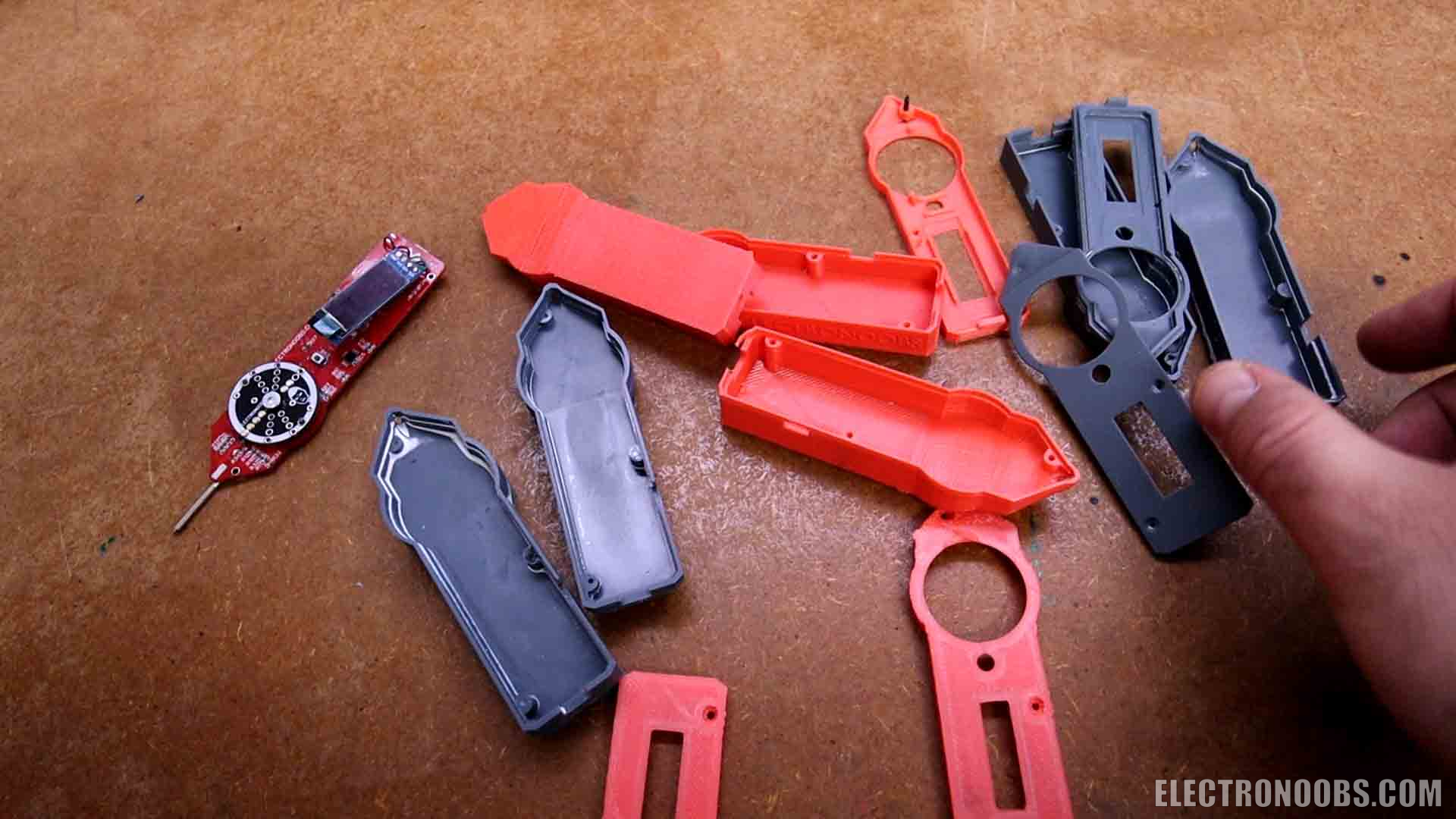
I’ve been designing an enclosure as well. It has a few versions. First I’ve printed it using PLA and an FDM printer. But if I want to get very small and also have good quality, the next versions were printed using a resin printer. The last two versions are these. One is very small but the other one also has a space for the negative probe. This would get wrap around like this and will stay inside its socket, which is pretty nice. The dial also has these two plastic parts. They get snapped on top of the dial PCB like this. Then I glue the screen on the top part. I pass the negative probe through this hole on the back. Then I solder it to the PCB and now I could close it. I do that using very small screws and that’s it.
Turn it on and start measuring. I can measure the voltage of a battery and values up to 60V both in positive and negative, different value resistors up to mega ohms, test for continuity on PCBs or short circuits, test for diodes reverse voltage, I can measure all values of capacitance, and also frequency. And in current mode, I can now easily measure up to 2 amps or more but I haven’t tested more than 2 amps. The PCB now also has a fuse for safety. So that’s how I’ve made my new multimeter. What do you think and what would you add extra to the meter. I would order the PCB with a different finish so it would last longer for the friction between the dial pins and the pads on the PCB. Also, I want to add a frequency generator mode and also temperature measurement, that would be quite easy, right? Check my website, for the GERBER files, the schematic, the full code and the part list together with the 3D design.
If my videos help you, consider supporting my work on my PATREON or a donation on my PayPal. Thanks again and see you later guys.
Comments


Leave a comment
Please login in order to comment.