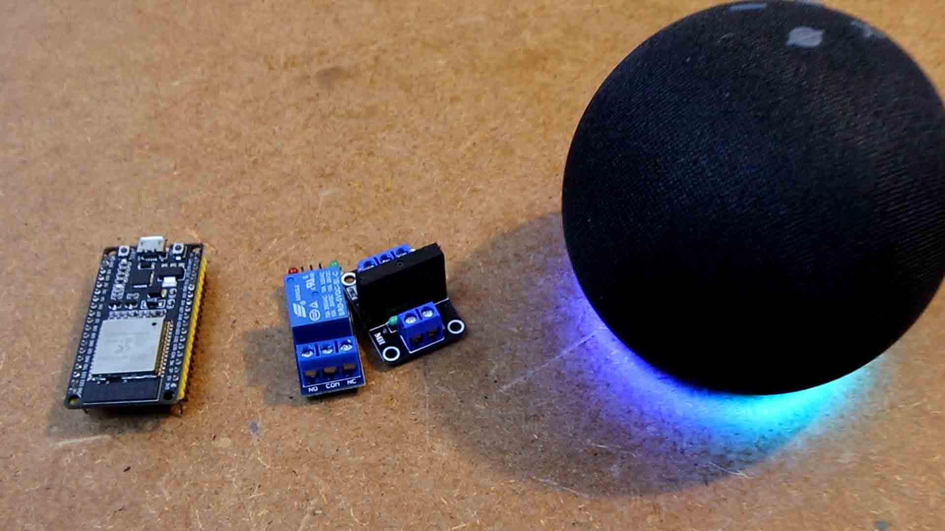
Today we learn how to control stuff using Alexa and an ESP32 and make it work with this PCB. We can control anything. Check example in the video below. And this works in any language, just change Alexa settings to your language and when you add the device, in the Arduino code, just write the name in that language. For example, it could work in Spanish if you want. This project works perfectly with my Noobix board from a previous project and this already has the ESP32, the programming pads, 12V and 5V voltage regulation and a solid state relay so is ready to turn on and off any device using your voice and Alexa. So guys, let’s get started.
What’s up my friends welcome back. To make this project we need an ESP32, a relay or even better, a solid-state relay or SSR and obviously, we need an Alexa device connected to the internet. But instead of making connections on a breadboard, if you want a more permanent and compact solution, just use my Noobix board that you could get from below. Remember, this PCB from a previous IOT project. Is the same PCB, it also works with Alexa. So if you want it, just download the GERBER files from below and you can order the PCBs from PCBWAY. Remember that I’ve changed the design so it wouldn’t have those small mistakes I’ve made and now the design has enough clearance and safety features. Please read all the updates on my previous post.
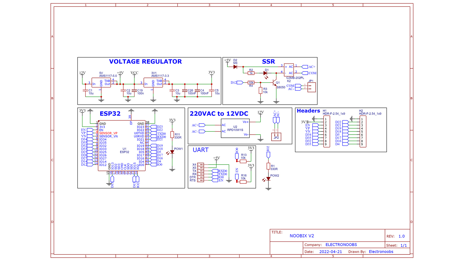
The schematic is quite easy. The basic configuration of the ESP32 chip with pullups to 3.3V for Enable and RST pins. The converter module give us 12V so we connect that in series with the AMS1117 regulators of 5 and 3.3V. The Relay circuit is simple. We use a BJT to connect pin 4 of the SSR to GND so we turn it ON. That's how when the D12 pin is HIGH, the NPN is ON so the Relay as well. We also have the UART pads for programming.
This below is the PCB that I’ve designed for my project. I’ve tried to make it as small as I could so it could fit inside of a basic wall electric box.
Since it works at 220V AC and the ESP32 needs 3 to 5V DC, I’m using a voltage converter module. That is very small and will give us a very steady 12V DC and 1 amp of current which is more than enough. Then, on the other side I’m using two linear regulators to get 5V and 3.3V. The ESP32 is controlling an SSR or solid-state relay. And that relay is connected to the output where we can connect our load. I’ve placed some pins around in case that you want to connect anything else to the ESP32. So guys go and download the GERBER files for the PCB from below. Then go to PCBWAY.COM and click the quote button. Add the size of the PCB (71 x 30mm), the amount of boards that you want and select a color. Since the green one is made faster, I selected the green solder mask. Save to cart and on the next page click the upload button. Now upload the GERBER files you’ve just downloaded from below my video. Make the order and receive my PCB in just a few days. Give them a quick inspection, but as always they look great.
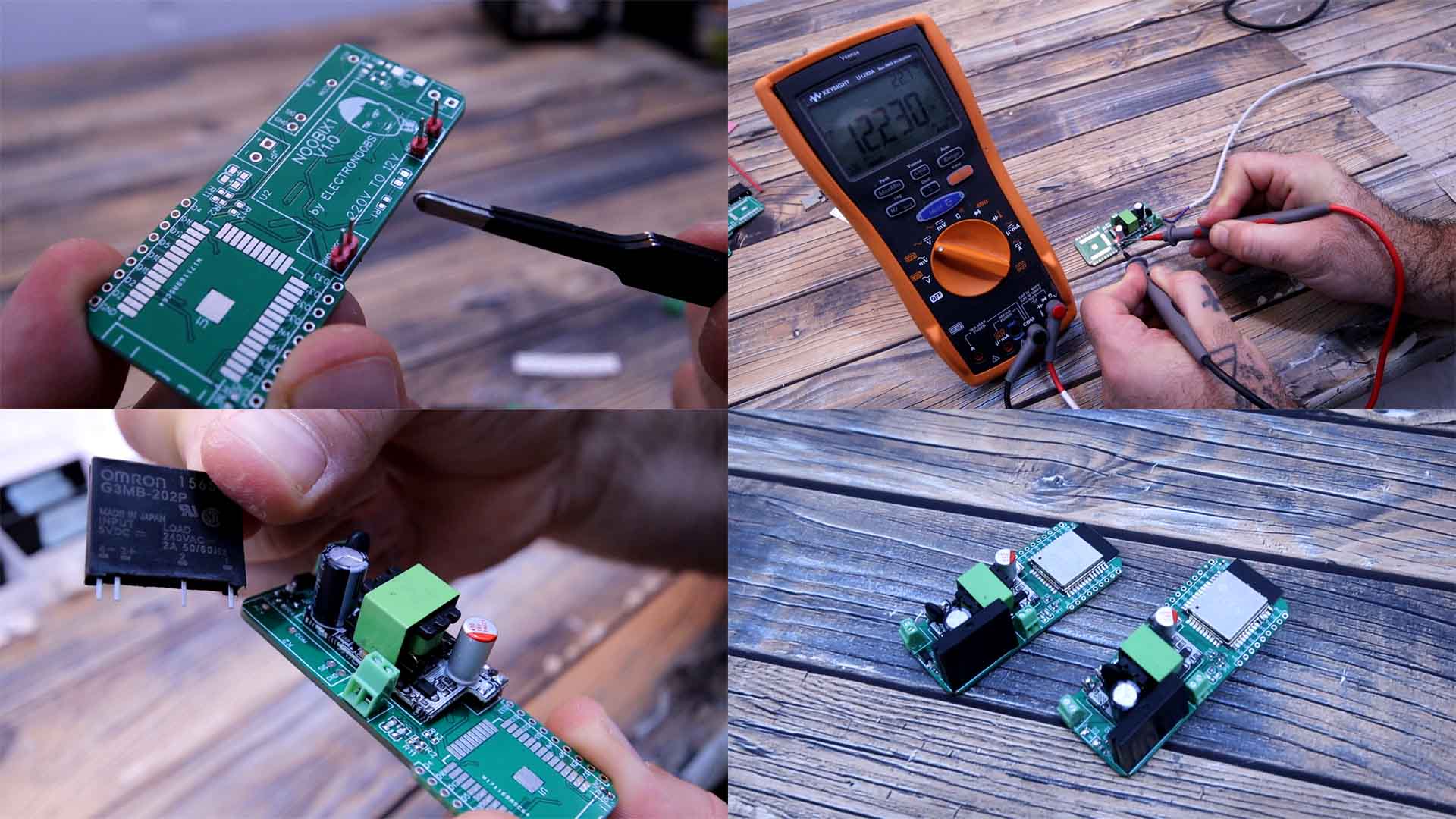
First I solder the voltage converter module. For that add 4 male pins. And on top of those pins we add the converter and we solder it. I also add the input and the output terminals. Then I carefully connect a 220V AC cable at the input. Be careful, and then connect it to power and check the voltage output of the module. If it is around 12V, we can continue. Then I solder the 5V and 3.3V regulators on the back of the PCB. Then I do the same and check the voltage output with my multimeter. Now that we have the voltage regulation part we can add the rest. I solder all the small resistors, capacitors, diodes and LEDs. I add in place the SSR. Finally I solder the ESP32 and the PCB is ready but we need a code uploaded with an external FTDI programmer connected to the UART pads on the back of the PCB.
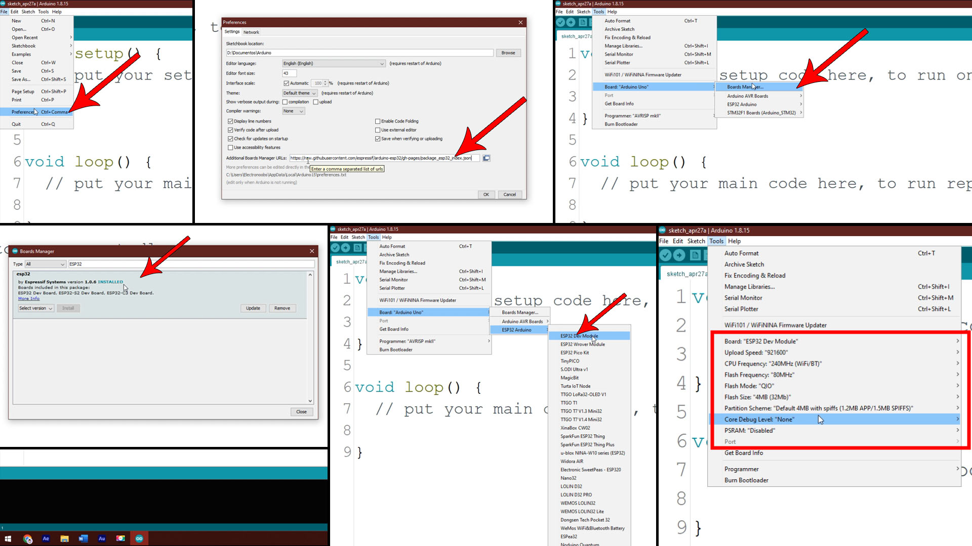
The EPS32 microcontroller has WIFI included adn the board is very small and you can get it from HERE . This controller works at 3.3V and to be able to program it we need a basic configuration with some pullups and buttons. This ESP32 development board already has that configuration and a USB connector together with an FTDI programmer IC so we can program it directly. Connect it to your PC and make sure your windows will install the drivers for the FTDI chip which in this case is the CP2102. Let’s make the ESP32 work with Arduino so open your Arduino IDE. Then go to preferences and in the extra URLs you have to paste this link from below.
Now go to tools, boards and click the boards manager. Search for ESP32. Select these boards and click install and as you can see I already have them installed. Now if you go once again to tools, boards, you can see that we can now select between a lot of ESP32 boards. In my case I select this one. ESP32 Dev Module. For the rest of the settings make sure you have the ones below if you're using the same DEV board as I am.
Now I write this simple code where I blink the GPIO 2. This Development board has an LED on that digital pin 2. Select the COM of the ESP32. Then click the upload button but make sure you press and maintain the boot button on the board. When you see the “connecting” message on the Arduino IDE, release the boot button and you will see that the code will get uploaded. Success, we now have a blinking LED so we have successfully uploaded a code to the ESP32 using Arduino and that was part 1.
int LED  = 2;

void setup() {
  pinMode(LED, OUTPUT);
}

void loop() {
  digitalWrite(LED, HIGH);
  delay(1000);
  digitalWrite(LED, LOW);
  delay(1000);
}
Now we could upload codes to the ESP32 board. Now let’s check the Alexa code. For that, go into sketch, libraries and open the manager. There search for fauxmo. Install that library that will do everything for us. Once installed, go to examples and open the basic file. Or just download the library and code from below.
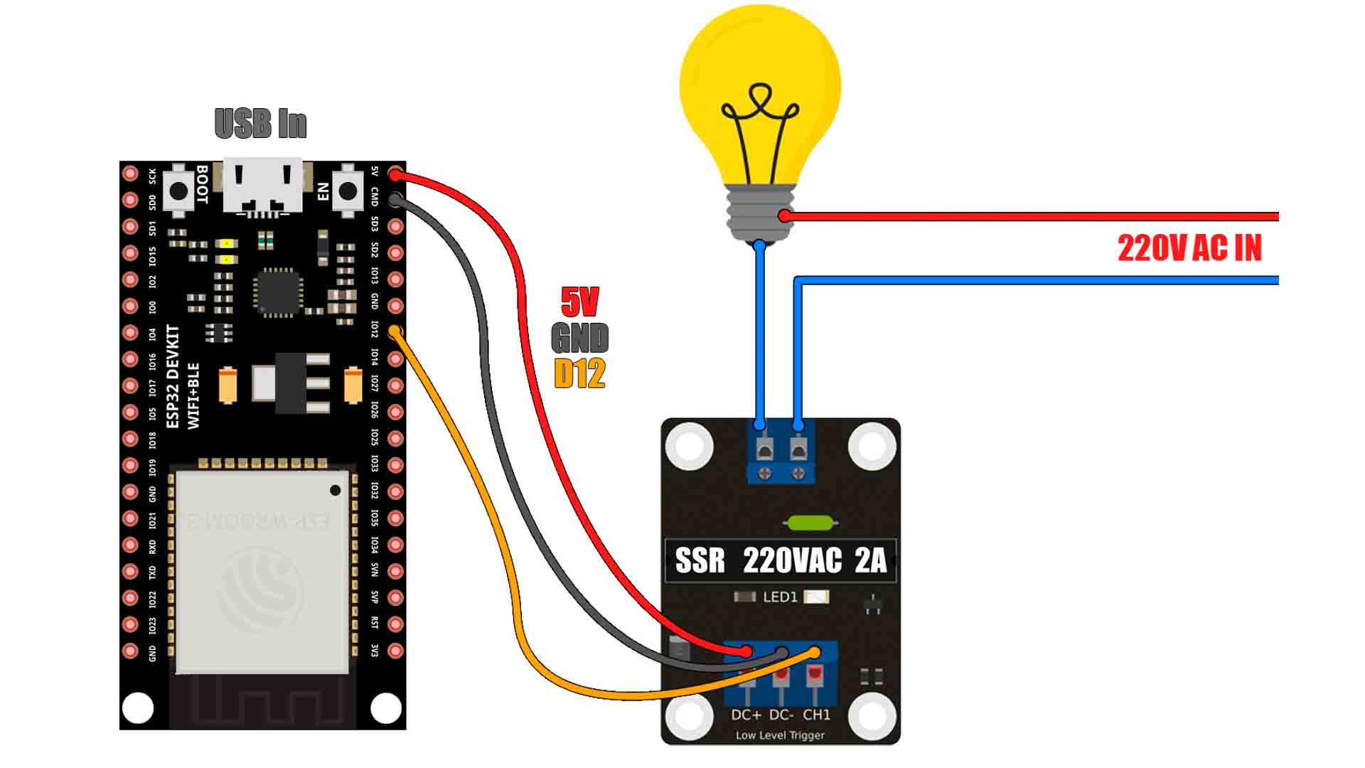
In the code we define the Alexa devices we want to create. By default it creates 4 different devices but for this example I only want one, so I delete all devices except the yellow one. For the yellow pin I select GPIO 12 but you could select any other pin if you want. I use pin 12 because that’s the one I’ve used on my Noobix board to control the relay, as you can see on the schematic above. Next, in the code for the yellow ID I change the name to workshop light. This is the word you will have to say later in order to activate it, so make sure you select good words. Scroll down and since I’ve deleted the other IDs, we also need to delete the pin modes and digital writes and only leave the yellow one. Scroll even more and here, in the if/else detection, delete the other devices and only leave the yellow one. Now compile and upload the code to the ESP32 board. Now the ESP will automatically connect to the WIFI name you’ve placed in the code
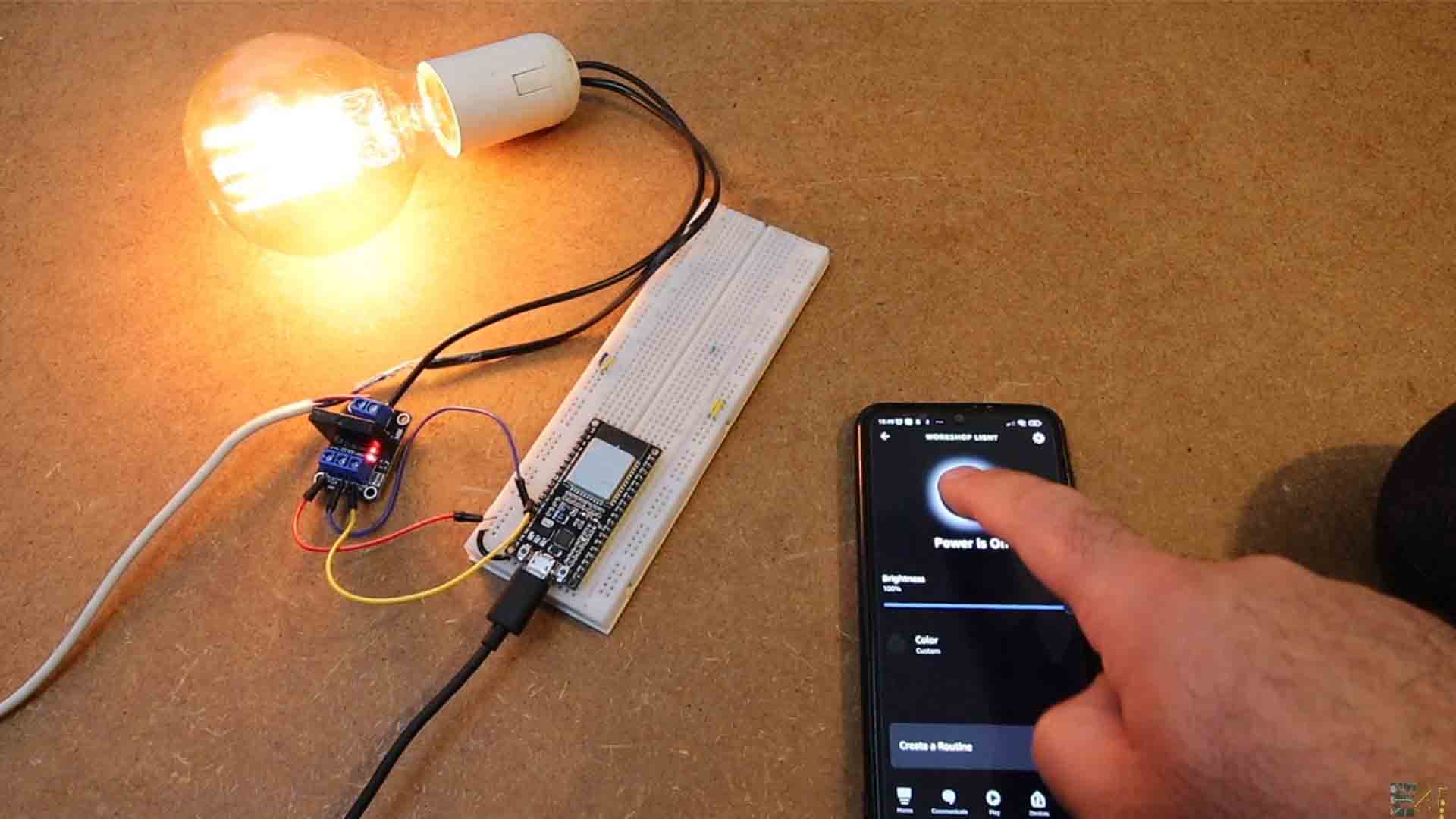
So go ahead and open the Alexa App on your smartphone. Go to devices and click the plus icon. In my case I select a light control. It doesn’t have a brand so scroll down and select other. As connection, select WIFI and then Alexa will discover devices. After a few seconds, it detected the workshop light so I click the add device button. There you go, as you can see, the workshop light is now on my devices list. If I press the on button, the relay connected on pin 12 will turn on. Also, I can say the command to Alexa and it will also turn on or off the relay, look.
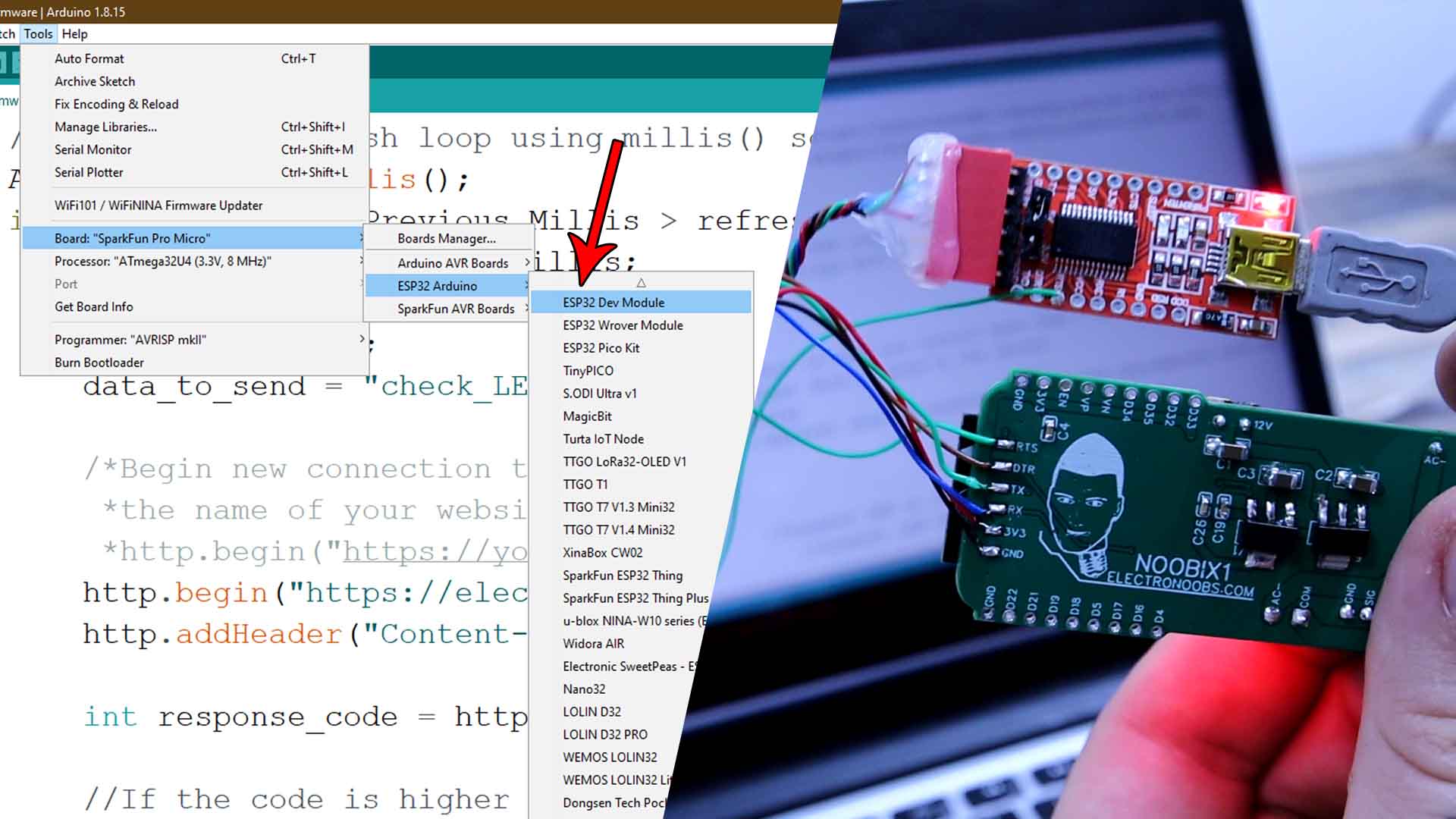
In case that you want to use my PCB and go in the Arduino IDE to tools, board and select the ESP DEV MODULE board. Connect wires from an FTDI module to the PCB:
| FTDI | Noobix |
|---|---|
| RX | TX |
| TX | RX |
| DTR | DTR |
| RST | RST |
| GND | GND |
| 5V | 5V |
That’s how easy is to use the NOOBIX board and control anything with Alexa. A fan, a light, your TV, an alarm, a motor, an LED strip or anything else. Because, once you get the data on the Arduino code, the rest is just Arduino code so you could add servo motors, displays, color LEDs, measuring devices such as temperature sensor, humidity sensor, movement sensor sand so on. Such a nice and easy project to play with. So get my PCB from above and order it at PCBWAY if you want to make the same project.
If my videos help you, consider supporting my work on my PATREON or a donation on my PayPal. Thanks again and see you later guys.