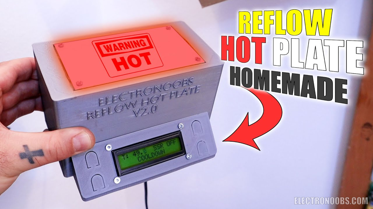
Hey guys. This will be a low-cost reflow hot plate for SMD components and will be homemade. If you remember, a few weeks ago I’ve made another reflow hot plate using a clothes iron of 3000W, a solid-state Relay with and Arduino and other components. That works great but it was a bit expensive, is too big for me and also it has way too much power for what I need. This time I’ve used a small heating plate that costs around 7 dollars.
And the rest is also very low-cost. A few dollars for the Arduino, the screen and the relay, a few more dollars for small components such as buttons, the switch, a fan and wires and the case is 3D printed. I’m sure that you wonder if the plastic case goes well with the heating plate. Well, it dose and I will explain you in this video how I’ve designed the case in such a way that the heat from the plate will never reach the plastic case and it’s quite interesting. I will show you all the components you need, how to assemble everything and we will make some tests with a few PCBs. So, what do you think? Will this project be able to reflow my components? So, let’s get started. BE CAREFUL WORKING WITH HIGH VOLTAGE.
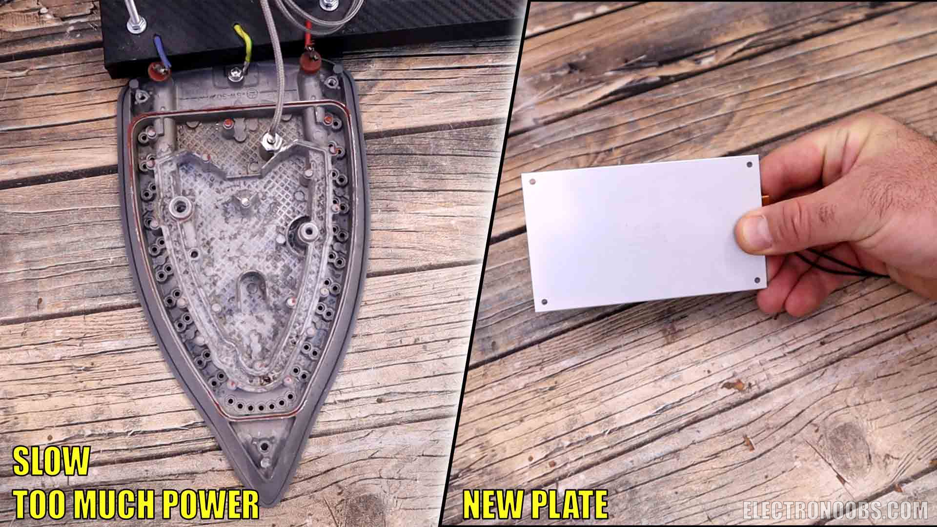
Let’s go over the part list first and then we make the project, we go over the code and finally we test it. Well, remember that in my previous reflow hot plate project, I was using a clothes iron as a heating plate. That had a lot of power (3000W), a lot more than we need, especially if we use low temperature solder paste. The problem with that iron was that measuring the temperature was a little bit difficult and slow. And why was that? Well, because first, I was using a thermocouple with an amplifier module. That module could send a measurement only each 200ms, so if you need faster reading, well you can’t... And second, the heat propagation was quite slow so till the real heat was reaching the thermocouples, the PID was already way behind so we always had over temperatures so I had to adjust the values manually. This time I will use a heating plate that I bought from AliExpress for just a few dollars.
~Part 2 - What we need?
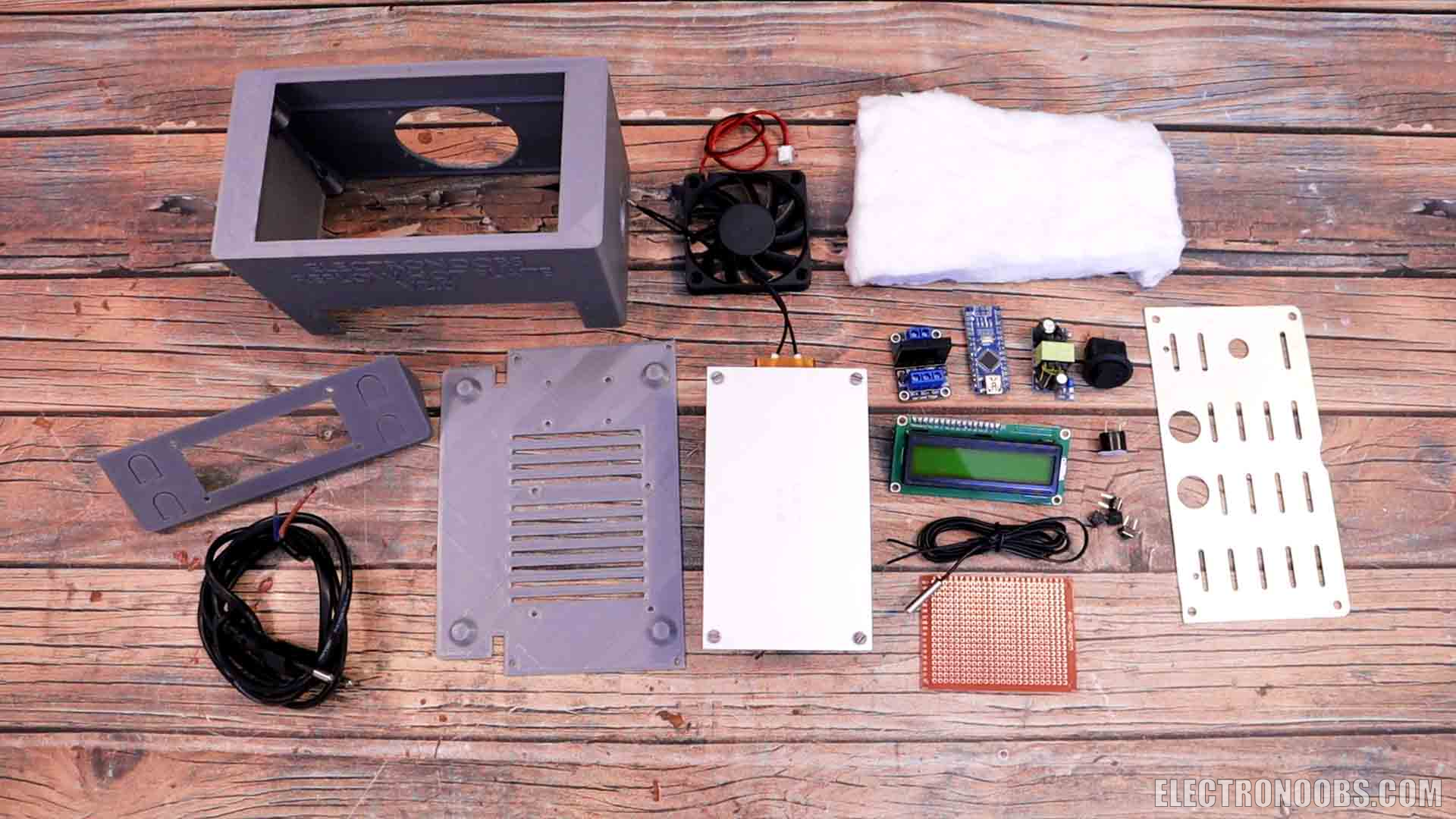
I still want to keep this project low cost so it would be cheaper than buying a reflow station. This plate has an internal heating resistor of around 450 ohms, so at 360V it could deliver around 280W of power which is 10 times less than the other project if you remember, that one was 3000W. On AliExpress, the plate was marked as 400W but I’m not sure that it could reach that. Anyway, I’ve realized that we don’t need more than 3 hundred watts. Is made of aluminum which will transfer the heat very fast. To control the power, we need a solid-state relay. You could use a big one like I’ve used before, but this time, since we have less power, I will use a smaller one that could work at 220V and could deliver 2 amps of current. It could also be easily controlled with an Arduino. So, obviously, we also need an Arduino which in this case, I will use again the Arduino NANO. To show the values I will use a 16 by 2 LCD screen with the i2c communication module so is easier to control. To measure the temperature, I will now use a thermistor instead of a thermocouple. We also need to use a 5V fan. The heater works at 220V but the rest of the digital part is working at 5V, so, to lower the voltage I will use a small converter. To turn the entire circuit on and off I will use a switch which also has an integrated LED and that’s nice to have. I also want to add a buzzer like this one for alarm notifications. Finally, to assemble the case you will see that we need some sort of metal plate. I will use this one and when we assemble the project I will explain why. Finally, for the case it would be better to make it out of metal but my workshop is not prepared for working with metal yet. That’s why I’ve made my design out of plastic.
I’ve made my case design out of plastic. This was printed in ABS so it will withstand more heat. The heating plate will stay on the top hole and it will never be in direct contact with the case. Also, the only way to transfer heat to the plastic case would be thought some screws that we add below the plate. And because they are long enough, the heat will transfer slowly. Even more, these screws will be connected to a metal plate I’ve told you before and only this plate will be in contact with the case. This plate will dissipate the heat even more and below we will have a cooling fan. Between the heating plate and the metal plate I also want to put some heat insulation cotton. This should protect the case even more from the heat of the top plate. And above all that, remember that our solder paste melting point is 172 degrees and you could also find some paste that will melt at 138. This temperature is still ok with ABS that melts at around 230 degrees or more.
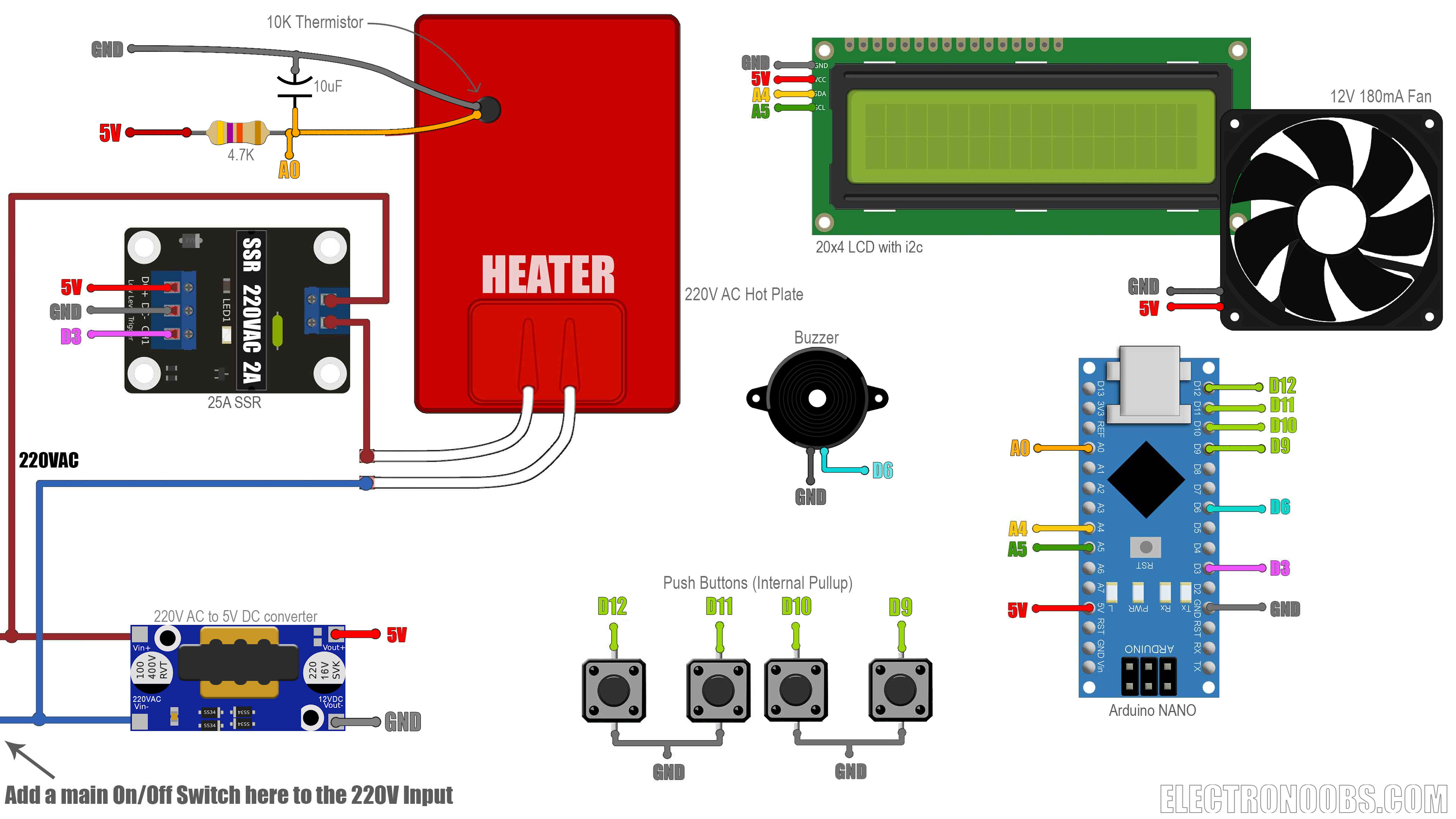
The schematic for this projec tis below. Be careful working with 220VAC because is quite dangerous so don't connect it to the main outle till you're not sure. Add the toggle swith btween the 220VAC input and the 5V converter. Insulate the converter module so it won't touch any low voltage part becasue that will damage the digital components. Once you have the case assembled, make the connections as below. Use thick wires for the power parts such as the 220V input and the relay + heater part. Add the pullup for the thermistor and a 10uF capacitor. Attatch the thermistor with good connection to the hot plate so it will measure the temperature. Supply all the digital part with 5V from the converter but check the output first wih a multimeter and make sure it's 5V, otherwise it might burn the Arduino and the rest.
Reflow Plate Homemade Schematic Arduino
~Part 5.1 - Case Assemble
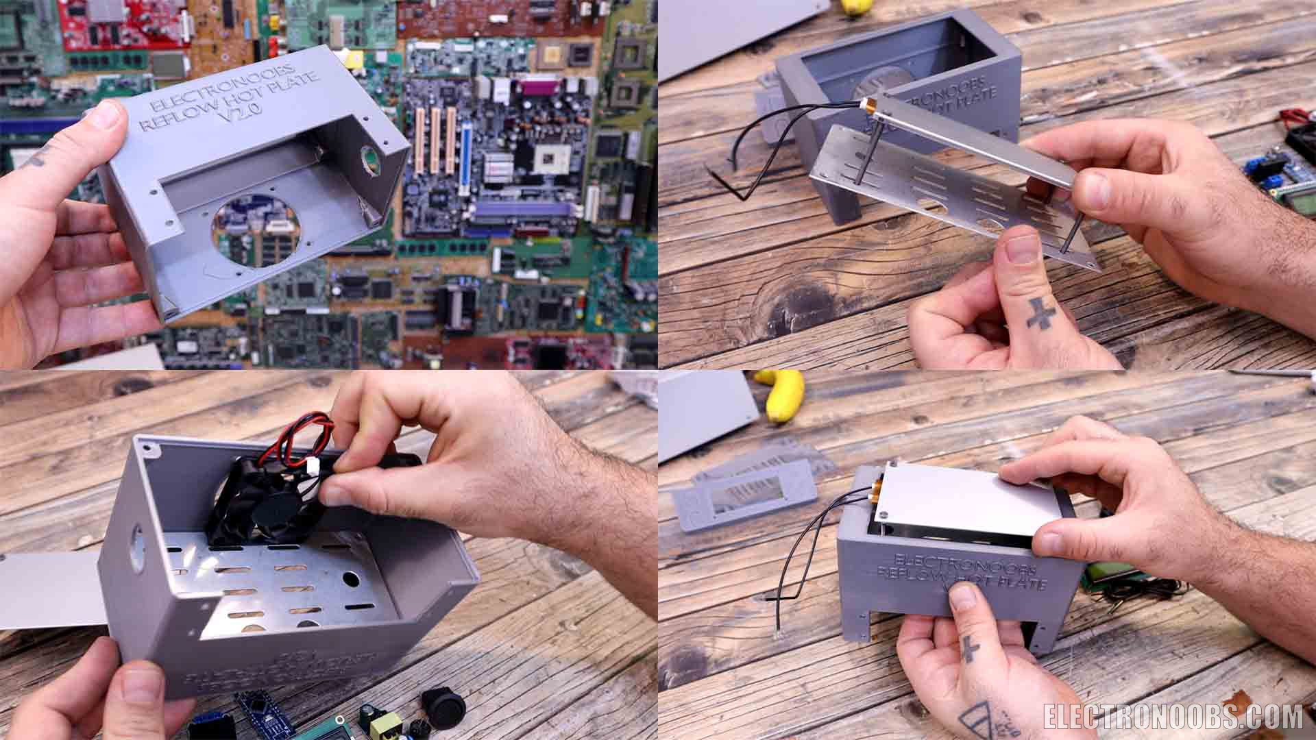
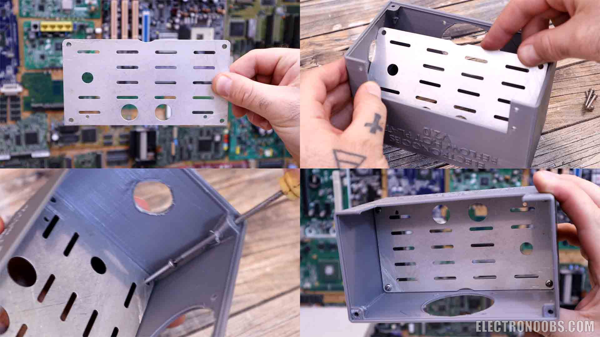
First we need to secure in place the heating plate. For that we need to add that metal plate below because if you will try to add it later, you won’t be able because we will have some plastic parts that will get in our way. So we must add the metal plate first. Inside the case, in the middle, we have 4 holes for screws. Make sure you add holes to your metal plate as well. 4 holes fort the heating plate screws and 4 more holes on each corner for the plastic case screws. Add the plate and tight the screws on each corner.
~Part 5.2 - Add the heating plate
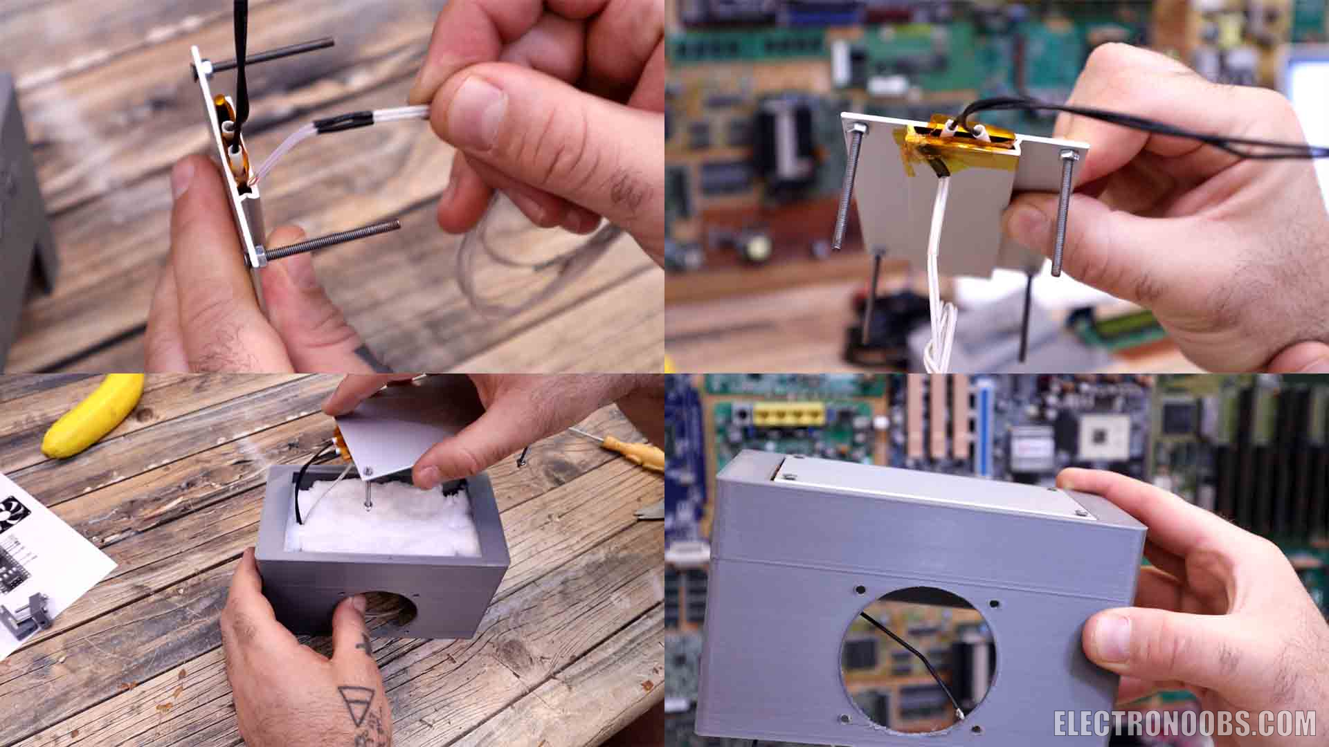
Now take the heating plate and add 4 long screws and tight a nut for each. At this point we also have to secure in place the thermistor on the metal plate so we can measure the temperature. In my case, since I still have a little bit of space aside of the heater element inside, I will add my thermistor inside here. I secure it in place with force and some KEPTON tape that could withstand very high temperatures. Then we add 4 more nuts that will define the maximum height. Before I add the heater inside, I cut some of this insulation foam. I cut it to size and also make holes for the screws. Then I add it in place over the metal plate. Now I add the heater and make sure you pass the power wires and the thermistor to the bottom side because the electronics will be below . From below I tight 4 more screws and the heater is in place. As you can see, the plate gets a little bit above the plastic case so we can easily remove our PCBs.
~Part 5.3 - LCD and Buttons
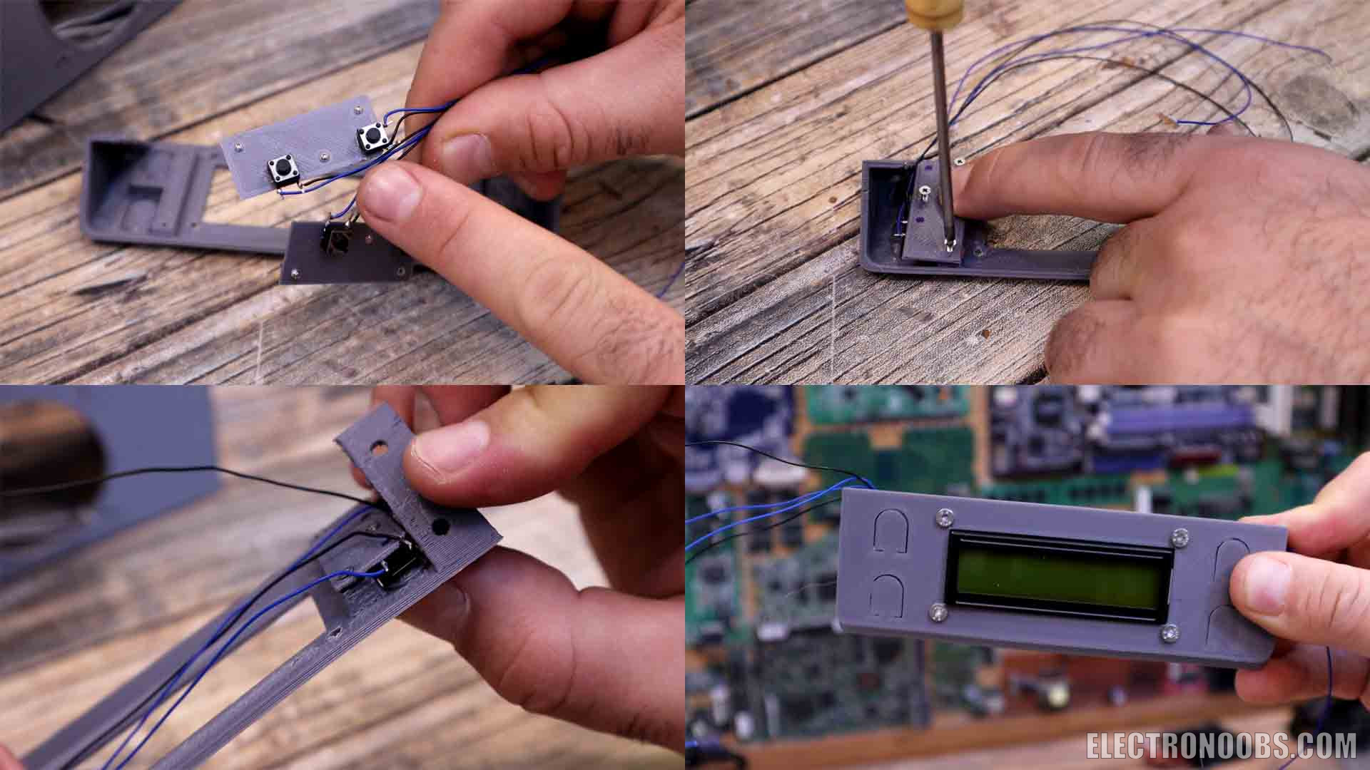
Now we assemble the small part. First, we have to add the push buttons. So, get 4 button and solder wires to each, one black wire for ground and a color one for signal. Each button will go behind a plastic pad I've also printed. Like that, when we push the pad of the case, we will push the button as well. To keep the buttons in place I’ve printed that small plastic part that will get screwed and support the buttons. So I decide where each button will ho and then I glue them to that small support part. Now I screw the support in place with some very tiny screws. Now when I push the plastic pad, the button is pressed, as you can see, we can hear the click.
Now we add the LCD in place. I add some screws and tight some nuts so we have some clearance. Then I add the LCD and add more nuts to keep it in place. Remember to also solder wires for power and the i2c communication
~Part 5.4 - Relay and Arduino
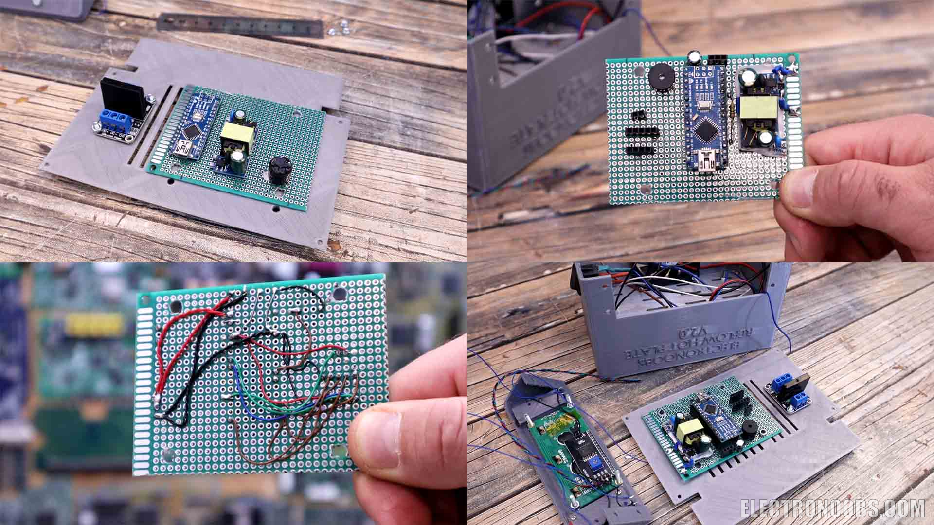
Now I get the relay, a prototyping PCB and the bottom 3D printed part. I screw in place the relay. Now I measure where the PCB will go in order to be screwed on the 4 holes of the printed part and I cut it to size. With the PCB in place I decide where to place the Arduino and the 5V converter and also some outputs and inputs. I solder the Arduino, the regulator and the buzzer in place and 4 sets of pins for the LCD, buttons, the fan and the thermistor. On the back I make the connections with thin wires and some thicker wires for power.
~Part 5.5 - Final Assemble
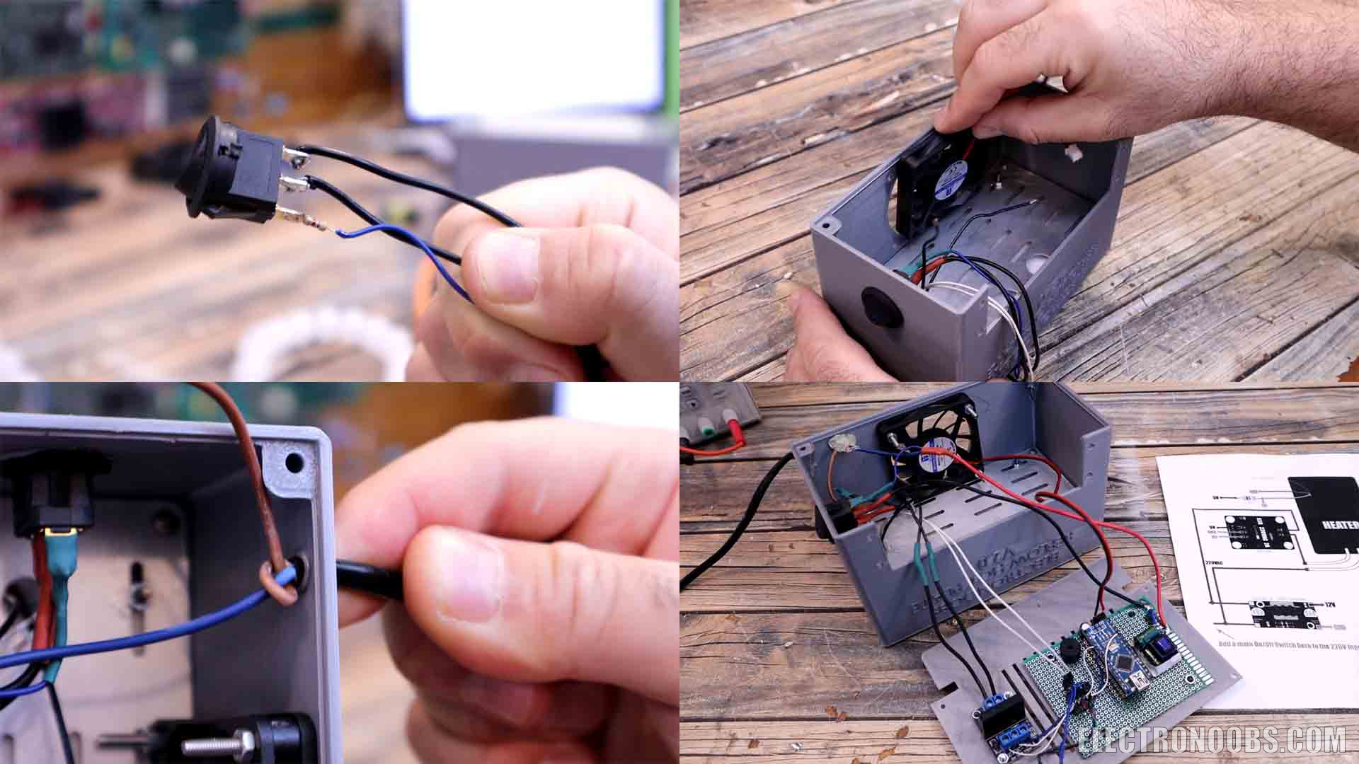
I get the on and off switch and solder 3 wires and the one with the LED also has a resistor to limit the current. I add this switch on the side of the case. Then I screw in place the cooling fan and make sure it will suck the air in. I get the power cable and pass it through the hole on the back and make a knot inside and also add some glue so it will stay in place. Finally, I make all the connections as in the schematic. Main power to the switch and from there we supply the relay and the 5V converter. The relay will then supply the heating plate and so on. Add insulation for all the wires! Everything is connected. Is time for the code so download it from the next part and upload it to the Arduino.
~ Part 6 - Temperature Control Code
First of all, if you want to see how to measure a thermsitor, check this tutorial here. In the code we set the loop refresh rate with the lines below. Then we read the temperature using a library for thermistors, so amke sure you download that library from the link below. According to the elapsed time and the real temperature, we control the PID code that will control the power of the Relay. What we try is to follow a curve, the melting curve of the solder paste. We apply the PID output to the Relay with a PWM signal and this will try to keep the power in such a way that the temperature will follow the setpoint. Once the code passes over all the stages, it will start the cooldown, and also ring the buzzer a few times in order to let the user know that the process is over but the plate is still hot. That’s pretty much what the code dose. I’ve uploaded the code and made sure the temperature control is ok and also tried different PID values till I’ve got decent results and I was closer to this curve for my solder paste.
/*//             ---Have in mind---
 *This code is a first version for the reflow hot plate project.
 *Tutorial here: http://electronoobs.com/eng_arduino_tut161.php
 *Please be careful working with "High Voltage" and double check everything.
 *Only use this project with supervision, never leave it plugged.
 *You can use this code at your own risk. I don't offer any guarantee that you
 *will get the same results as I did and you might have to adjsut some PID values */

#include <thermistor.h>             //Downlaod it here: http://electronoobs.com/eng_arduino_thermistor.php
thermistor therm1(A0,0);            //The 3950 Thermistor conencted on A0
//LCD config
#include <Wire.h>                   //Included by Arduino IDE
#include <LiquidCrystal_I2C.h>      //Downlaod it here: http://electronoobs.com/eng_arduino_liq_crystal.php
LiquidCrystal_I2C lcd(0x27,16,2);   //Define LCD address as 0x27. Also try 0x3f if it doesn't work.

//Inputs and Outputs
int but_1 = 12;
int but_2 = 11;
int but_3 = 10;
int but_4 = 9;
int SSR = 3;
int buzzer = 6;
int Thermistor_PIN = A0;

//Variables
unsigned int millis_before, millis_before_2;    //We use these to create the loop refresh rate
unsigned int millis_now = 0;
float refresh_rate = 500;                       //LCD refresh rate. You can change this if you want
float pid_refresh_rate  = 50;                   //PID Refresh rate
float seconds = 0;                              //Variable used to store the elapsed time
int running_mode = 0;                           //We store the running selected mode here
int selected_mode = 0;                          //Selected mode for the menu
int max_modes = 3;                              //For now, we only work with 1 mode...
bool but_3_state = true;                        //Store the state of the button (HIGH OR LOW)
bool but_4_state  =true;                        //Store the state of the button (HIGH OR LOW)
float temperature = 0;                          //Store the temperature value here
float preheat_setoint = 140;                    //Mode 1 preheat ramp value is 140-150ºC
float soak_setoint = 150;                       //Mode 1 soak is 150ºC for a few seconds
float reflow_setpoint = 200;                    //Mode 1 reflow peak is 200ºC
float temp_setpoint = 0;                        //Used for PID control
float pwm_value = 255;                          //The SSR is OFF with HIGH, so 255 PWM would turn OFF the SSR
float MIN_PID_VALUE = 0;
float MAX_PID_VALUE = 180;                      //Max PID value. You can change this.
float cooldown_temp = 40;                       //When is ok to touch the plate

/////////////////////PID VARIABLES///////////////////////
/////////////////////////////////////////////////////////
float Kp = 2;               //Mine was 2
float Ki = 0.0025;          //Mine was 0.0025
float Kd = 9;               //Mine was 9
float PID_Output = 0;
float PID_P, PID_I, PID_D;
float PID_ERROR, PREV_ERROR;
/////////////////////////////////////////////////////////

void setup() {
  //Define the pins as outputs or inputs
  pinMode(SSR, OUTPUT);
  digitalWrite(SSR, HIGH);        //Make sure we start with the SSR OFF (is off with HIGH)
  pinMode(buzzer, OUTPUT);
  digitalWrite(buzzer, LOW);
  pinMode(but_1, INPUT_PULLUP);
  pinMode(but_2, INPUT_PULLUP);
  pinMode(but_3, INPUT_PULLUP);
  pinMode(but_4, INPUT_PULLUP);
  pinMode(Thermistor_PIN, INPUT);

  lcd.init();                     //Init the LCD
  lcd.noBacklight();              //Activate backlight
  Serial.begin(9600);
  tone(buzzer, 1800, 200);
  millis_before = millis();
  millis_now = millis();
}

void loop() {
  millis_now = millis();
  if(millis_now - millis_before_2 > pid_refresh_rate){    //Refresh rate of the PID
    millis_before_2 = millis();

    temperature = therm1.analog2temp();

    if(running_mode == 1){
      if(temperature < preheat_setoint){
        temp_setpoint = seconds*1.666;                    //Reach 150ºC till 90s (150/90=1.666)
      }

      if(temperature > preheat_setoint && seconds < 90){
        temp_setpoint = soak_setoint;
      }

      else if(seconds > 90 && seconds < 110){
        temp_setpoint = reflow_setpoint;
      }

      //Calculate PID
      PID_ERROR = temp_setpoint - temperature;
      PID_P = Kp*PID_ERROR;
      PID_I = PID_I+(Ki*PID_ERROR);
      PID_D = Kd * (PID_ERROR-PREV_ERROR);
      PID_Output = PID_P + PID_I + PID_D;
      //Define maximun PID values
      if(PID_Output > MAX_PID_VALUE){
        PID_Output = MAX_PID_VALUE;
      }
      else if (PID_Output < MIN_PID_VALUE){
        PID_Output = MIN_PID_VALUE;
      }
      //Since the SSR is ON with LOW, we invert the pwm singal
      pwm_value = 255 - PID_Output;

      analogWrite(SSR,pwm_value);           //We change the Duty Cycle applied to the SSR

      PREV_ERROR = PID_ERROR;

      if(seconds > 130){
        digitalWrite(SSR, HIGH);            //With HIGH the SSR is OFF
        temp_setpoint = 0;
        running_mode = 10;                  //Cooldown mode
      }
    }//End of running_mode = 1


    //Mode 10 is between reflow and cooldown
    if(running_mode == 10){
      lcd.clear();
      lcd.setCursor(0,1);
      lcd.print("    COMPLETE    ");
      tone(buzzer, 1800, 1000);
      seconds = 0;              //Reset timer
      running_mode = 11;
      delay(3000);
    }
  }//End of > millis_before_2 (Refresh rate of the PID code)


  millis_now = millis();
  if(millis_now - millis_before > refresh_rate){          //Refresh rate of prntiong on the LCD
    millis_before = millis();
    seconds = seconds + (refresh_rate/1000);              //We count time in seconds


    //Mode 0 is with SSR OFF (we can selcet mode with buttons)
    if(running_mode == 0){
      digitalWrite(SSR, HIGH);        //With HIGH the SSR is OFF
      lcd.clear();
      lcd.setCursor(0,0);
      lcd.print("T: ");
      lcd.print(temperature,1);
      lcd.setCursor(9,0);
      lcd.print("SSR OFF");

      lcd.setCursor(0,1);
      if(selected_mode == 0){
        lcd.print("Select Mode");
      }
      else if(selected_mode == 1){
        lcd.print("MODE 1");
      }
      else if(selected_mode == 2){
        lcd.print("MODE 2");
      }
      else if(selected_mode == 3){
        lcd.print("MODE 3");
      }


    }//End of running_mode = 0

     //Mode 11 is cooldown. SSR is OFF
     else if(running_mode == 11){
      if(temperature < cooldown_temp){
        running_mode = 0;
        tone(buzzer, 1000, 100);
      }
      digitalWrite(SSR, HIGH);        //With HIGH the SSR is OFF
      lcd.clear();
      lcd.setCursor(0,0);
      lcd.print("T: ");
      lcd.print(temperature,1);
      lcd.setCursor(9,0);
      lcd.print("SSR OFF");

      lcd.setCursor(0,1);
      lcd.print("    COOLDOWN    ");
    }//end of running_mode == 11

    //Mode 1 is the PID runnind with selected mode 1
    else if(running_mode == 1){
      lcd.clear();
      lcd.setCursor(0,0);
      lcd.print("T: ");
      lcd.print(temperature,1);
      lcd.setCursor(9,0);
      lcd.print("SSR ON");

      lcd.setCursor(0,1);
      lcd.print("S");  lcd.print(temp_setpoint,0);
      lcd.setCursor(5,1);
      lcd.print("PWM");  lcd.print(pwm_value,0);
      lcd.setCursor(12,1);
      lcd.print(seconds,0);
      lcd.print("s");
    }//End of running_mode == 1


  }


  ///////////////////////Button detection////////////////////////////
  ///////////////////////////////////////////////////////////////////
  if(!digitalRead(but_3) && but_3_state){
    but_3_state = false;
    selected_mode ++;
    tone(buzzer, 2300, 40);
    if(selected_mode > max_modes){
      selected_mode = 0;
    }
    delay(150);
  }
  else if(digitalRead(but_3) && !but_3_state){
    but_3_state = true;
  }


  ///////////////////////////////////////////////////////////////////
  ///////////////////////////////////////////////////////////////////
  if(!digitalRead(but_4) && but_4_state){
    if(running_mode == 1){
      digitalWrite(SSR, HIGH);        //With HIGH the SSR is OFF
      running_mode = 0;
      selected_mode = 0;
      tone(buzzer, 2500, 150);
      delay(130);
      tone(buzzer, 2200, 150);
      delay(130);
      tone(buzzer, 2000, 150);
      delay(130);
    }

    but_4_state = false;
    if(selected_mode == 0){
      running_mode = 0;
    }
    else if(selected_mode == 1){
      running_mode = 1;
      tone(buzzer, 2000, 150);
      delay(130);
      tone(buzzer, 2200, 150);
      delay(130);
      tone(buzzer, 2400, 150);
      delay(130);
      seconds = 0;                    //Reset timer
    }
  }
  else if(digitalRead(but_4) && !but_4_state){
    but_4_state = true;
  }
}
~Part 7 - Close the case
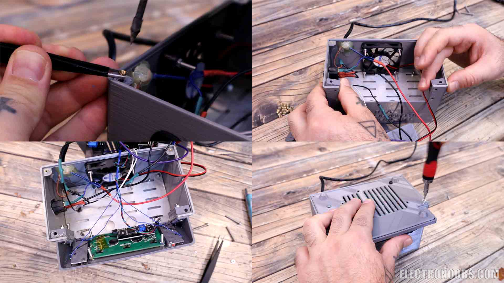
Now that the code is uploaded and we know it works, we can close the case. Take a few insertion thread nuts. Using your soldering iron, we insert them into the holes of the plastic case. As you cans see, we only have holes on two corners. The other two will be added using the small printed parts. We have one for each corner and they will stay in place with the same screws we use to connect the LCD part to the main case. So using two screws we make a sandwich between the LCD part, the main case and these small parts for the screw. Once they are in place, I use my soldering iron once again ad add two more insertion nuts. Now we can add the bottom part and close the entire case and the project is ready. It looks quite good right? But dose it work?
~Part 8 - Reflow Test
Connect it to power and flip the switch. The internal LED of the switch should turn on indicating that power is connected. The LCD will also start and tell the user to select a mode. On the screen we can see temperature, if the relay is ON and when the mode is running, we can see the setpoint, the PWM value and the elapsed time in seconds. I prepare a testing PCB with some solder paste and I add a few components using the tweezers. I place the PCB over the heating plate. From the menu I select mode 1, which is the only mode for now, and I press run. We start with the ramp where we go up to 150 degrees, then the soak part and finally we go above that temperature and reflow the components. Once the components are soldered, we enter the cooldown mode. At this point you can remove the PCB from the plate. The reflow process was OK but some components moved so I had to use the tweezers and put them in place. But in overall, the reflow process was a success.
~Part 9 - See full Video
So guys, what do you think? The entire project is quite low-cost since the heating plate was just a few dollars, the Arduino, the relay and the small components as well and the case is 3D printed. You have the full part list and the prices on the first chapter above. So, do you like my project? If so, comment below or give this video a like.
If my videos help you, consider supporting my work on my PATREON or a donation on my PayPal. Thanks again and see you later guys.
Hey, the link for thermistor lib is not active anymore: http://electronoobs.com/eng_arduino_thermistor.php
Could you please share the valid one?
Thanks!
 @DPilot
2 days ago
@DPilot
2 days ago


Leave a comment
Please login in order to comment.