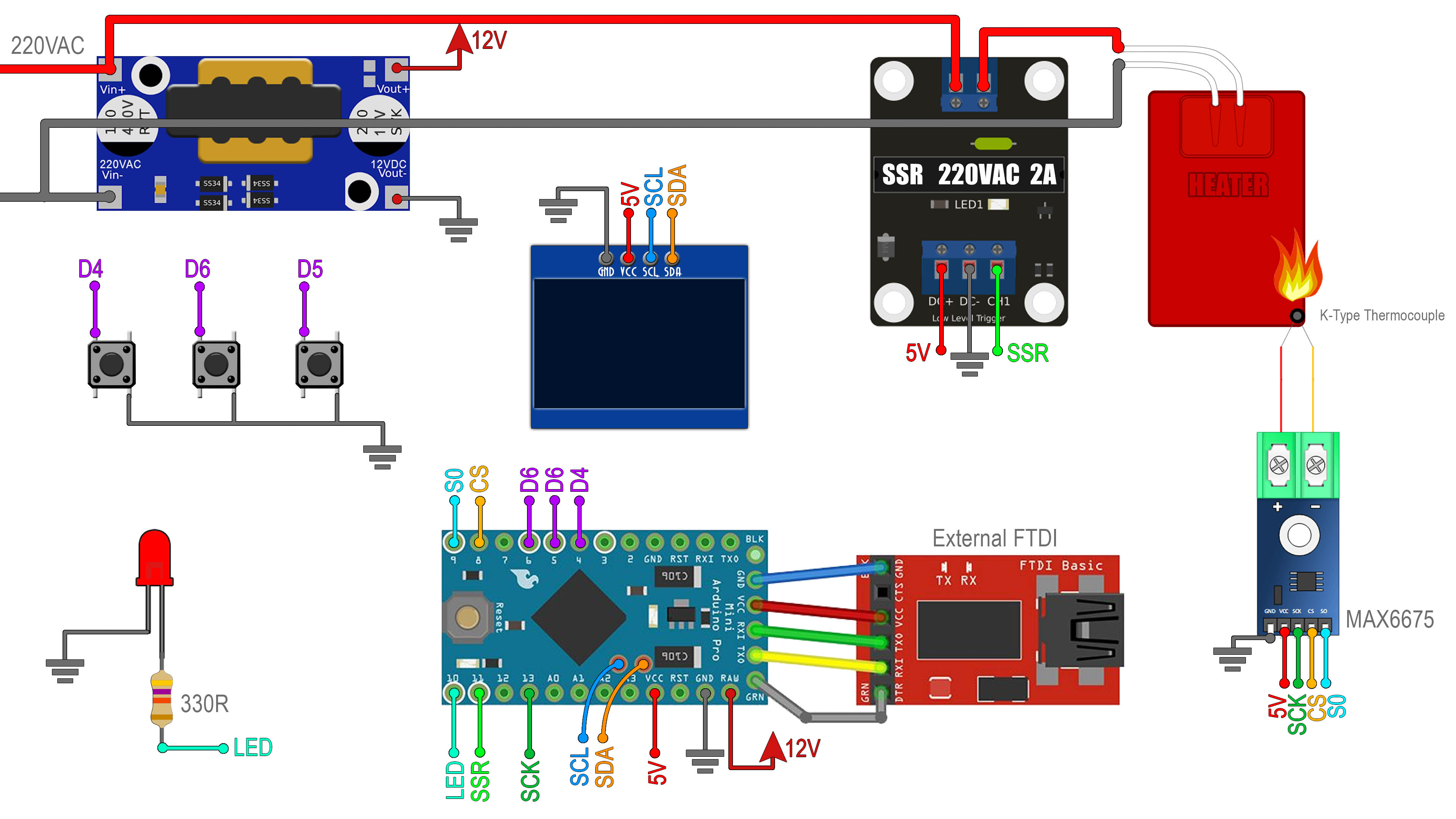
Below you have all the connections for this project. First connect 220VAC from your mains, to the 220VAC to 12VDC converter. Connect the 12V DC to the RAW pin of the Arduino Pro Mini and this will regulate 5V on the Vcc pin. Share GND with all the modules. Then connect the 5V from the Aruino to the OLED screen, MAX6675 amplifier and SSR module. Finally connect the digital pins to the SSR, amplifier LED and screen. Also connect GND to all push buttons and the other pin of each button connected to digital inputs D3, D6 and D5. Connect one side of the main 220VAC directy to the heater load and the other side of the high voltage is connected to on pin of the SSR. THe other pin of the SSR is connected to the load heater. Add the K-type thermocouple and that's it.