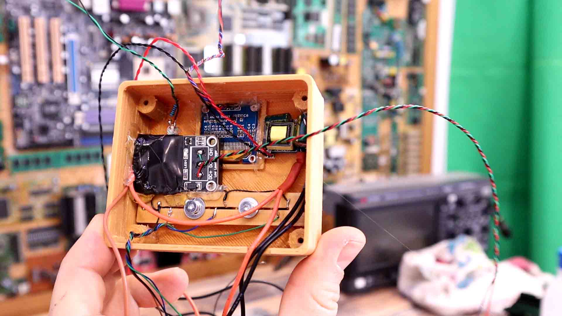

This controller could control 220V AC power and measure the temperature with a thermocouple. It could go up to 500ºC. We can set the setpoint temperature adn it will use some sort of PID control to activate a SSR (solid state relay) and control the pwoer applied to a heater. This could only be used with resistive loads. Big inductive loads might create huge current spikes since the control is pulsed. You have the schematic, part list and code below.
Below you have all the parts needed for this project. The Arduino has a 5V regulator, so we can use the small 220VAC to 12VDC converter and supply the Arduino on the RAW pin with 12V and it will regulate its own 5V for the rest of the difital part. Use the K type thermocouple and the MAX6675 amplifier to measure temperature. Use a bigger SSR if you want more power, the one I've used is 2A and 220V so around 450W. You could easily find relays up to 40A at 220V so around 8000W.

Below you have all the connections for this project. First connect 220VAC from your mains, to the 220VAC to 12VDC converter. Connect the 12V DC to the RAW pin of the Arduino Pro Mini and this will regulate 5V on the Vcc pin. Share GND with all the modules. Then connect the 5V from the Aruino to the OLED screen, MAX6675 amplifier and SSR module. Finally connect the digital pins to the SSR, amplifier LED and screen. Also connect GND to all push buttons and the other pin of each button connected to digital inputs D3, D6 and D5. Connect one side of the main 220VAC directy to the heater load and the other side of the high voltage is connected to on pin of the SSR. THe other pin of the SSR is connected to the load heater. Add the K-type thermocouple and that's it.
Add wires to all modules and the screen, LED and so on. Solder wires to the push buttons and glue them on the small 3D printed part. Then screw that part in place so we could use the buttons. Then, I solder thick wires to the 220VAC to 12VDC converter. Two wires to each input. Do the same with the relay and add shrinking tubes for insulation. I glue everything inside the 3D printed case. Add as much insulationa s you can for the relay adn high voltage converter. Check adn double check the connections in the scheamtic.

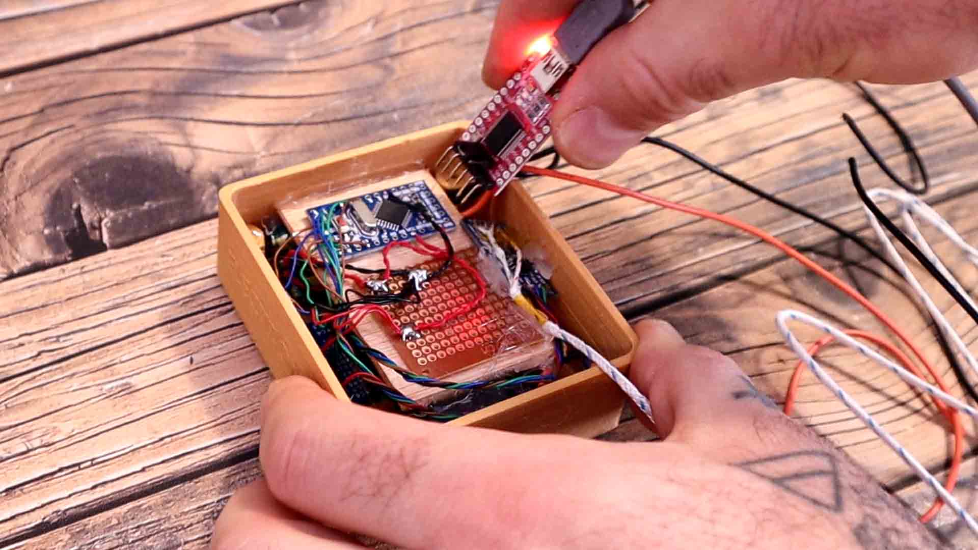
On top of all the modules I add a piece of plywood. Then I glue the Arduino and a small PCB. Here I make all the connections with thin wires. Now I have everythign connected and ready for the code. Fot that I use an external FTDI programmer and upload the code from below.

Below you have the full code for the controller. We have 3 main loops. When the heater is cold and we just turn it on we have the ramp up loop, where the SSR is fully turned on. When we get close to the desired value, we start some sort of PID control. That would change the pulses applied to the SSR. The frequency of these pulses must be low since the AC signal is only 50 or 60 hertz depending on your country. With some lines in the code I set that pulse to 30 hertz. When we power off the controller, we go to the cool down loop where we power off the relay but we are still monitoring the temperature. To detect the 3 push buttons, I’m using interruptions and a debounce in order to make sure we don’t read noise. Read the code line by line for more.
int thermoDO = 9;
int thermoCS = 8;
int thermoCLK = 13;
MAX6675 thermocouple(thermoCLK, thermoCS, thermoDO);

//Arduino Pins
#define SSR_PIN  11
#define but_up  4
#define but_down  5
#define but_stop  6
#define led  10
So now the controller is ready. I can close the case. We have a few wires coming out from the controller+. One is the the thermocouple. Two more are for 220V AC input and the other two are for the load connection, just as we have with the other commercial controllers. To change the PID values, check the first lines in the code and change the P, I and D values. To make good tests is hard without a closed environment and a thermocoupe inside the heater ot a metal block to keep a constant value.
I hope you like this tutorial and maybe you have learned something new. If my videos help you, consider supporting my work on my PATREON or a donation on my PayPal. Thanks again and see you later guys.