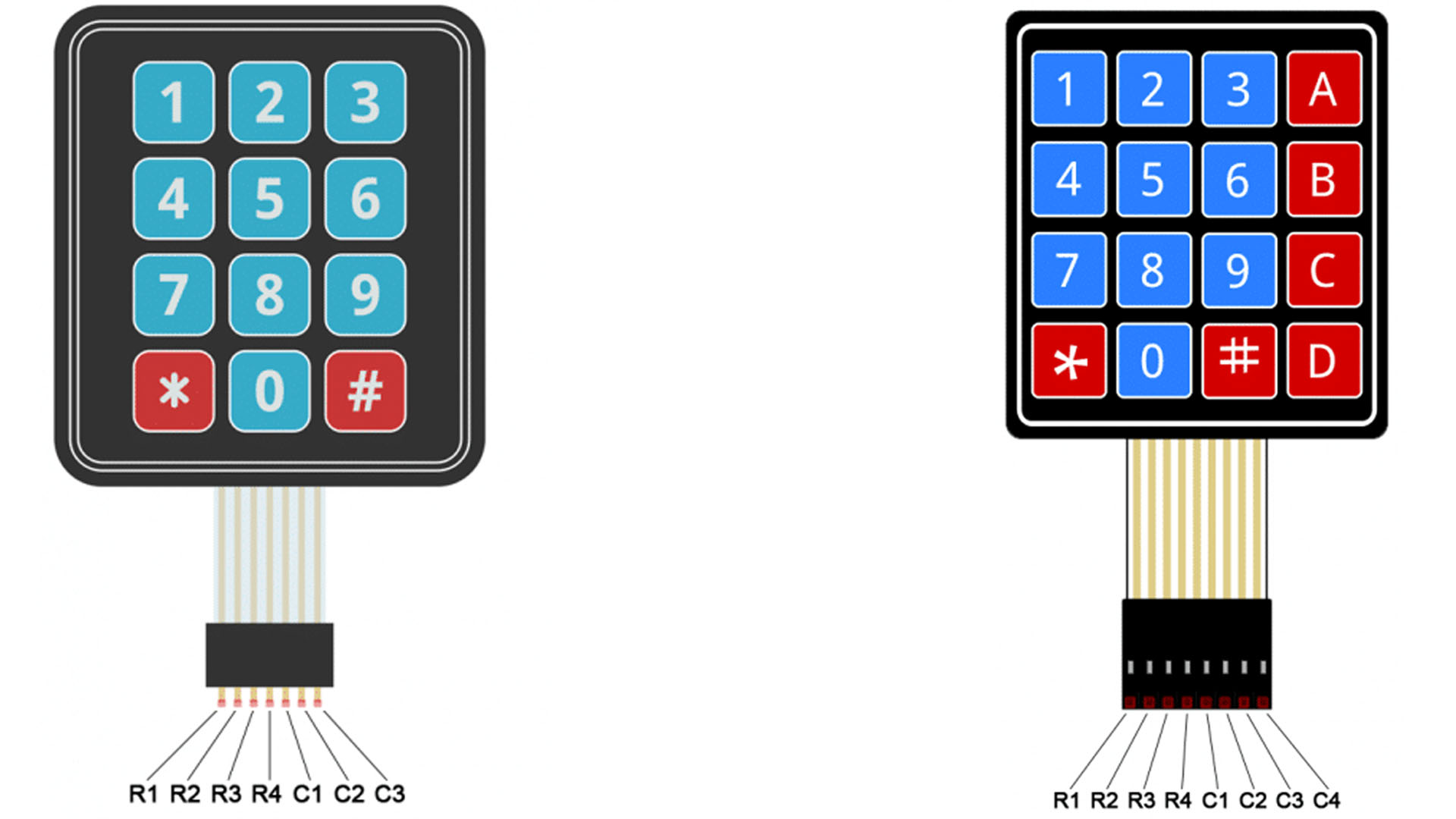
A keypad is a nice simple method of accepting user input into your project. These come in a number of styles and generally there are 2 types a 5×4 keypad and a 4×4 keypad but it could be of any other amount of rows and columns. The numbers stand for the rows and columns, so a 3×4 keypad has 3 columns and 4 rows. These are simple to connect to your Arduino, in the example below we simply connect the 8 connections to 8 pins on our Arduino
In the animated example below, you can see how a keypad works. Usually, for 12 buttons like below, you would need 12 digital pin of the Arduino. But instead of using a single wire for each button, what we do with the keypad library is using "multiplexing". In this case we connect only 7 pins instead of 12. Columns and rows. The Arduino code will alternately apply a high pulse to each column, one by one, as you can see below. So imagine this: If when we apply a high pulse to pin3, if button 7 is pressed, then we will have that high pulse to the pin6, right? Because the button makes the connection between colum of pin3 and row of pin6. Of course, the code will make this very fast, so we won't skip any pushed button. So all we have to do in the code is to read which row pin is "high" when each of the columns pins are "high". Easy right?
On eBay you will find two types of keypads. With 3 columns and 4 rows and with 4 rows and columns. As you can see below, these are the connections for each pin for rows and columns, so now you know how to connect this to the Arduino and change the pins in the code, in case that you use a different pin.
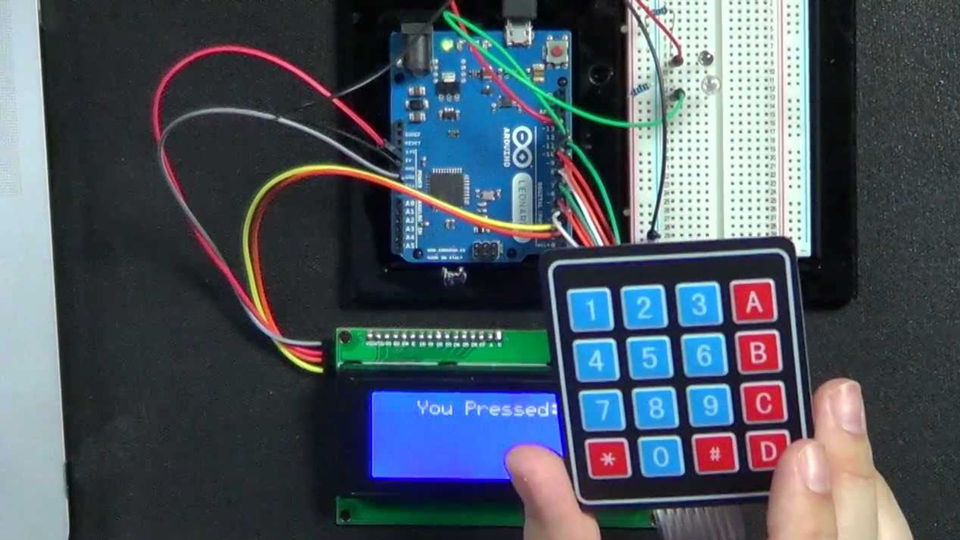
Connect the Keypad to pins from D2 to D9. The example is for a 4 by 5 keypad so we need 8 pins. The code would be the same for a 3x4 but we need to remove a colums. Anyway, connect a i2c LCD if you have one. If not, don't worry. The example code will also print the same think on the serial monitor so you could see the results.
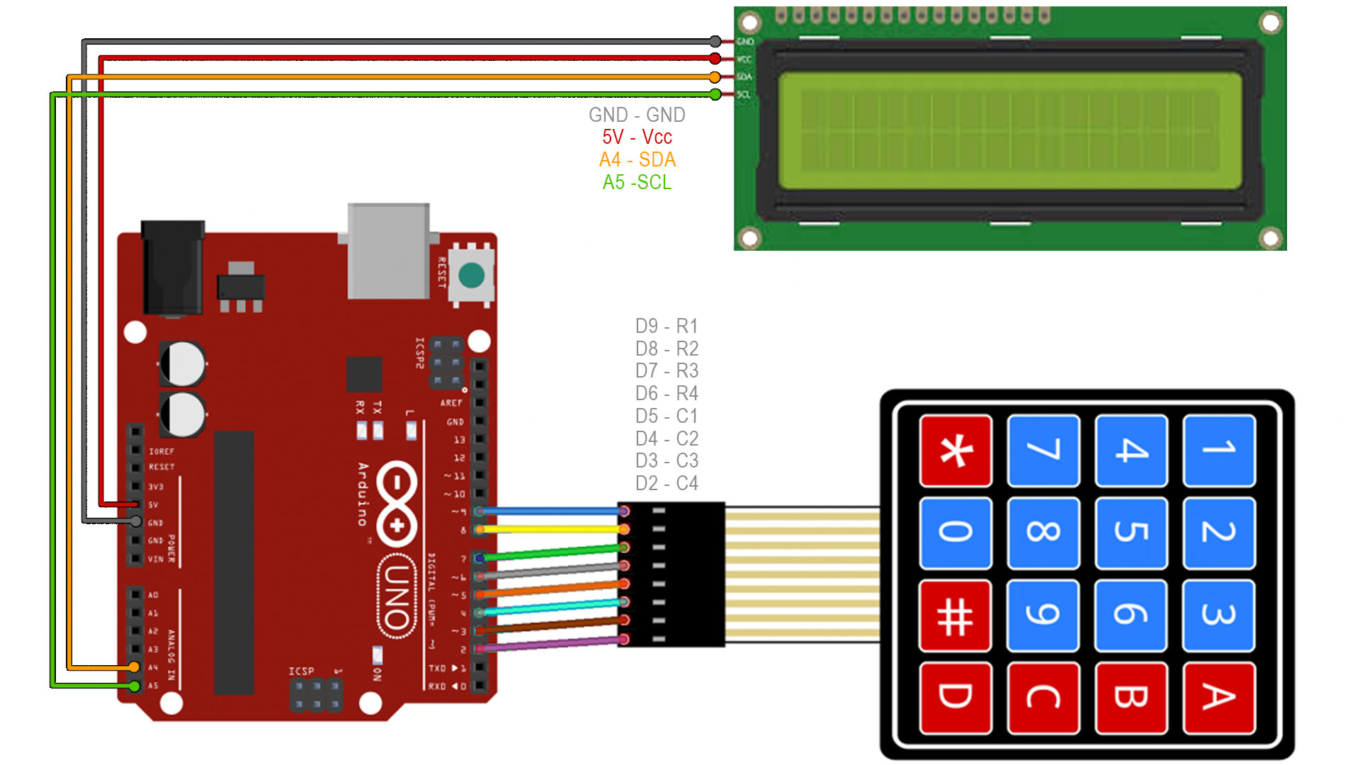
Make the connections as above. Connect a i2c LCD if you have one. If not, don't worry. The example code will also print the same think on the serial monitor so you could see the results. Get the libraries from the links below. Install them to the Arduino IDE using the include .zip library. Upload the code to the Arduino and open serial monitor ot look at the LCD. Each time you press a button, it will print the character.
#include "Adafruit_Keypad.h"            //Downlaod library here: https://electronoobs.com/eng_Arduino_Adafruit_Keypad.php
#include <Wire.h>
#include <LiquidCrystal_I2C.h>          //Download it here: https://www.electronoobs.com/eng_arduino_liq_crystal.php
LiquidCrystal_I2C lcd(0x3f,16,2);       //slave address sometimes can be 0x3f or 0x27. Try both!


const byte ROWS = 4; // rows            //Number of rows your keypad has
const byte COLS = 4; // columns         //Number of columns your keypad has
/* Define the symbols on the buttons of the keypads. This could bea ny other symbol.
   For example, if when I press the "1! button you want to print a '?' just change
   the '1' below with a '?'*/
char keys[ROWS][COLS] = {
  {'1','2','3','A'},
  {'4','5','6','B'},
  {'7','8','9','C'},
  {'*','0','#','D'}
};

byte rowPins[ROWS] = {9, 8, 7, 6};    //connect to the row pinouts of the keypad (as in example schematic)
byte colPins[COLS] = {5, 4, 3, 2};    //connect to the column pinouts of the keypad (as in example schematic)

//initialize an instance of class NewKeypad
Adafruit_Keypad customKeypad = Adafruit_Keypad( makeKeymap(keys), rowPins, colPins, ROWS, COLS);

void setup() {
  Serial.begin(9600);         //Start serial communication with the LCD (for serial monitor)
  delay(10);
  lcd.init();                 //Start i2c communication with the LCD
  lcd.backlight();            //Activate backlight
}

void loop() {
  // put your main code here, to run repeatedly:
  customKeypad.tick();

  while(customKeypad.available()){        //only run this part if a new keypad was pressed
    keypadEvent e = customKeypad.read();
    Serial.print((char)e.bit.KEY);        //Print character on serial monitor
    lcd.clear();
    lcd.setCursor(0,0);
    lcd.print((char)e.bit.KEY);           //Print character on LCD

    if(e.bit.EVENT == KEY_JUST_PRESSED){
      Serial.println(" pressed");
    }
    else if(e.bit.EVENT == KEY_JUST_RELEASED){
      Serial.println(" released");
    }
  }

  delay(10);
}
This is the same but it will store each pressed character in a String so we can print the entire text. Compile and upload.
#include "Adafruit_Keypad.h"            //Downlaod library here: https://electronoobs.com/eng_Arduino_Adafruit_Keypad.php
#include <Wire.h>
#include <LiquidCrystal_I2C.h>          //Download it here: https://www.electronoobs.com/eng_arduino_liq_crystal.php
LiquidCrystal_I2C lcd(0x3f,16,2);       //slave address sometimes can be 0x3f or 0x27. Try both!


const byte ROWS = 4; // rows            //Number of rows your keypad has
const byte COLS = 4; // columns         //Number of columns your keypad has
String text = "";


/* Define the symbols on the buttons of the keypads. This could bea ny other symbol.
   For example, if when I press the "1! button you want to print a '?' just change
   the '1' below with a '?'*/
char keys[ROWS][COLS] = {
  {'1','2','3','A'},
  {'4','5','6','B'},
  {'7','8','9','C'},
  {'*','0','#','D'}
};

byte rowPins[ROWS] = {9, 8, 7, 6};    //connect to the row pinouts of the keypad (as in example schematic)
byte colPins[COLS] = {5, 4, 3, 2};    //connect to the column pinouts of the keypad (as in example schematic)

//initialize an instance of class NewKeypad
Adafruit_Keypad customKeypad = Adafruit_Keypad( makeKeymap(keys), rowPins, colPins, ROWS, COLS);

void setup() {
  Serial.begin(9600);         //Start serial communication with the LCD (for serial monitor)
  delay(10);
  lcd.init();                 //Start i2c communication with the LCD
  lcd.backlight();            //Activate backlight
}

void loop() {
  // put your main code here, to run repeatedly:
  customKeypad.tick();

  while(customKeypad.available()){        //only run this part if a new keypad was pressed
    keypadEvent e = customKeypad.read();
    char Pressed = (char)e.bit.KEY;
    text = text + Pressed;

    lcd.clear();
    lcd.setCursor(0,0);
    lcd.print(text);

    Serial.println(text);

  }

  delay(10);
}
I hope that you like this tutorial. If you consider supporting my work, buy my PCBs on my shop, or maybe consider supporting me on PATREON or if you want, make a PayPal donation. Thank you very much.