A rotary encoder is a type of position sensor that converts the angular position (rotation) of a knob into an output signal that is used to determine what direction the knob is being rotated. Due to their robustness and fine digital control; they are used in many applications including robotics, CNC machines and printers. There are two types of rotary encoder – absolute and incremental. The absolute encoder gives us the exact position of the knob in degrees while the incremental encoder reports how many increments the shaft has moved (steps).The rotary encoder used in this tutorial is of an incremental type.
In the animated example below, you can see how an encoder works. Inside the encoder we have some copper pads (brown color in the animation). These are connected to GND. Then we have two pins, clock and data, with a pullup to 5V. In this way, when the pin is in open circuit, it will be "HIGH" or 5V. While rotationg, these two pins will touch the copper pads, pulling the output to GND since the pads are directy connected to GND. So, each time we touch a copper pad, we have a "LOW" pulse. By counting these pulses, we can count steps. If we detect 10 pulses for example, then the encoder jumped 10 copper pads. By knowing how many pads (steps )the encoder has, we can calculate the angle of rotation.
But! at the same time, using both pins we can also detect the direction of rotation. In the example below, as you can see both pins start with an output of 5V since non is touching the copper pads. If we rotate to the right, then the clock pin will be the first one to drop to GND. If we rotate to the left, the data pin will be the first one to drop to GND. So, just by detecting which pin will change its level first, we can detect the direction of rotation. Doing this with the Arduino is very simple.
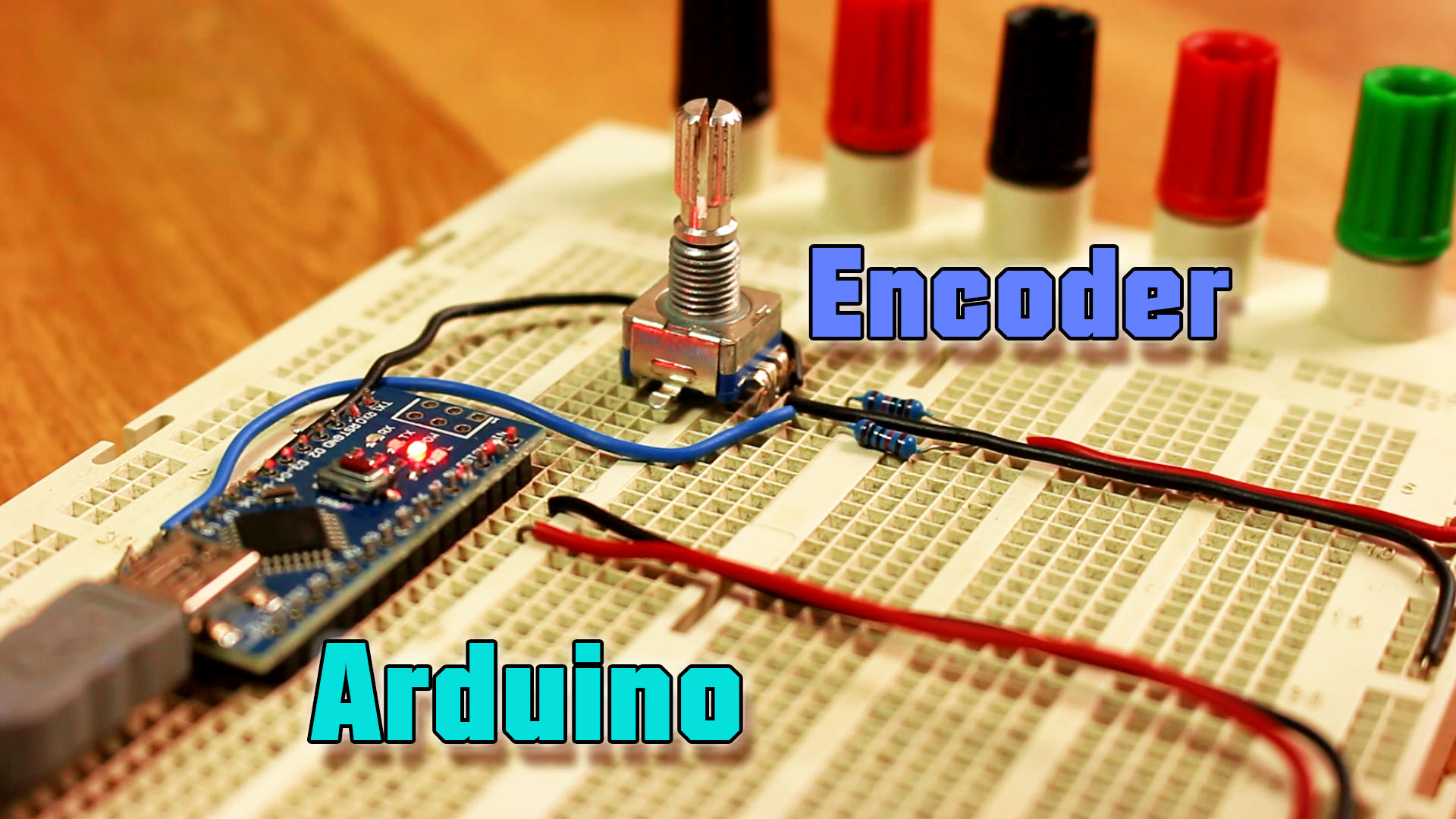
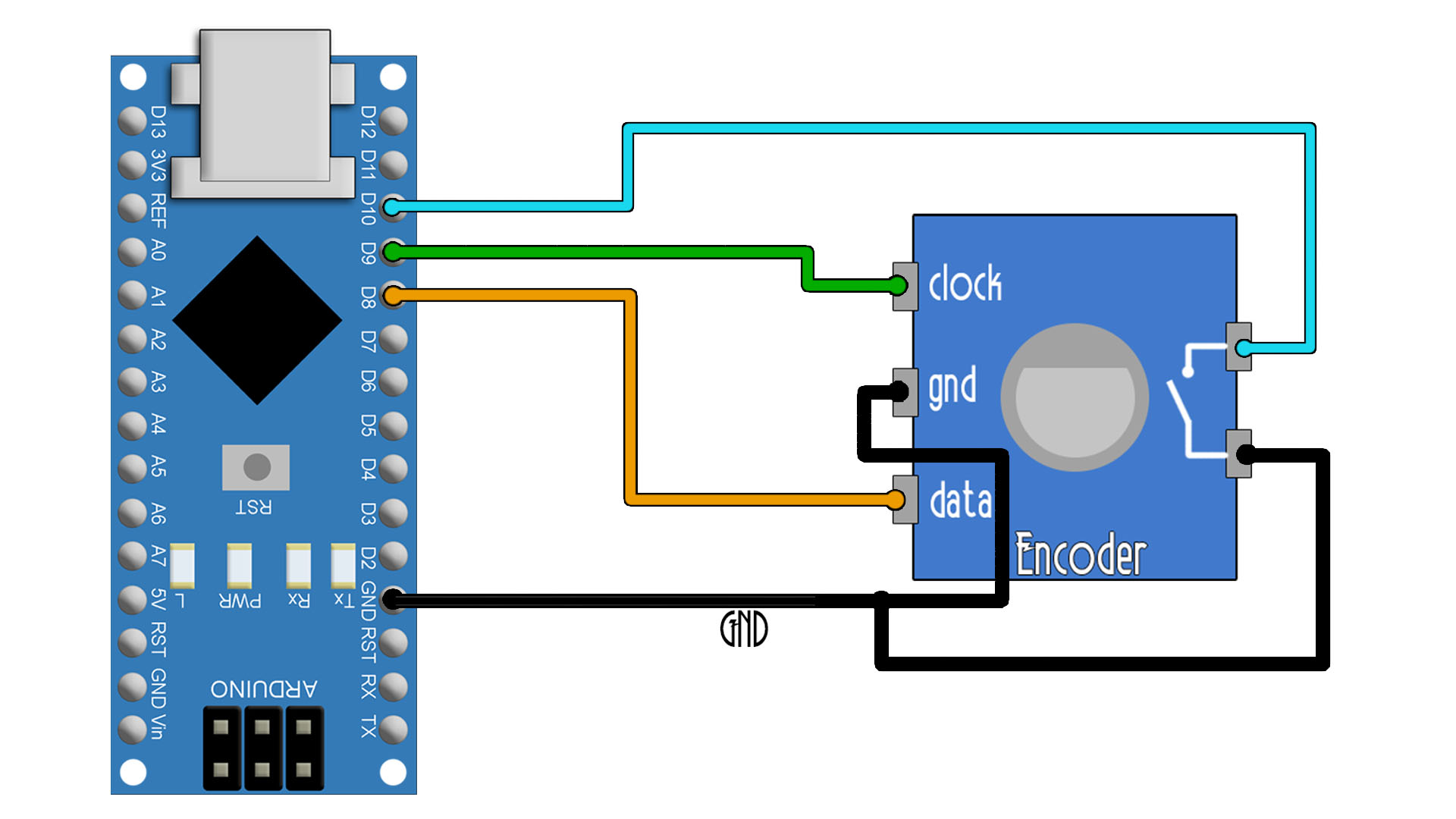
Ok, as you can see below, we have connected the encoder data and clock pins to the Arduino on D8 adn D9. The encoder also has a push button inside taht we could use, so I've connected that to D10. We need pullups for each pin, but instead of adding an external resistor, we can define the pin in the ARduino code as INPUT_PULLUP, and that will do the job. Connect GND to the encoder GND pin.
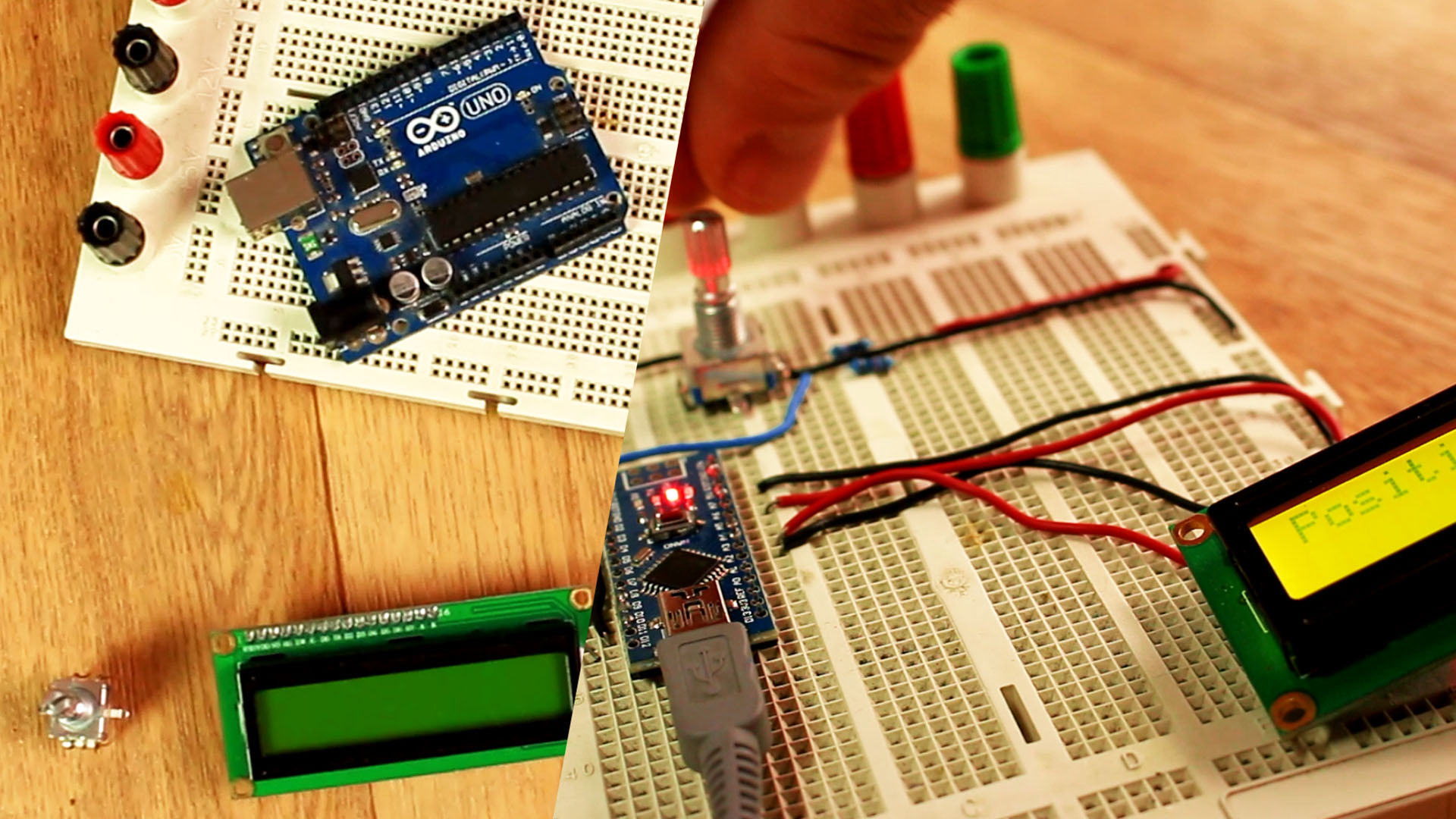
This example doesn't need any library nor the LCD screen. Just print the result on the serial monitor. Make connections as above, connect the USB to the Arduino and then upload the code. Open serial monitor at 9600 bauds and start rotating the encoder and pusing the button to test it. The counter value will increase and decrease. If you want to create a menu, just put limits to the counter and depending on that counter value, decide the position in the menu. Download the .zip code from below or just copy+paste. Read all coments in the code to understand each step.
// Rotary Encoder Inputs
#define Clock 9   //Clock pin connected to D9
#define Data 8    //Data pin connected to D8
#define Push 10   //Push button pin connected to D10

int counter = 0;                    //Use this variable to store "steps"
int currentStateClock;              //Store the status of the clock pin (HIGH or LOW)
int lastStateClock;                 //Store the PREVIOUS status of the clock pin (HIGH or LOW)
String currentDir ="";              //Use this to print text
unsigned long lastButtonPress = 0;  //Use this to store if the push button was pressed or not

void setup() {

  /*  Set encoder pins as inputs with pullups. If you use the Encoder Module, you don't need
   *  pullups for Clock and Data, only for the push button.*/
  pinMode(Clock,INPUT_PULLUP);
  pinMode(Data,INPUT_PULLUP);
  pinMode(Push, INPUT_PULLUP);

  // Setup Serial Monitor
  Serial.begin(9600);

  // Read the initial state of Clock pin (it could be HIGH or LOW)
  lastStateClock = digitalRead(Clock);
}

void loop() {

  // Read the current state of CLK
  currentStateClock = digitalRead(Clock);

  // If last and current state of Clock are different, then "pulse occurred"
  // React to only 1 state change to avoid double count
  if (currentStateClock != lastStateClock  && currentStateClock == 1){

    // If the Data state is different than the Clock state then
    // the encoder is rotating "CCW" so we decrement
    if (digitalRead(Data) != currentStateClock) {
      counter --;
      currentDir ="Counterclockwise";
    } else {
      // Encoder is rotating CW so increment
      counter ++;
      currentDir ="Clockwise";
    }

    Serial.print("Direction: ");
    Serial.print(currentDir);
    Serial.print(" | Counter: ");
    Serial.println(counter);
  }

  // We save last Clock state for next loop
  lastStateClock = currentStateClock;

  // Read the button state
  int btnState = digitalRead(Push);

  //If we detect LOW signal, button is pressed
  if (btnState == LOW) {
    //if 50ms have passed since last LOW pulse, it means that the
    //button has been pressed, released and pressed again
    if (millis() - lastButtonPress > 50) {
      Serial.println("Button pressed!");
    }

    // Remember last button press event
    lastButtonPress = millis();
  }

  // Put in a slight delay to help debounce the reading
  delay(1);
}
Ok, the problem with the code above is that if you make any other process in the void loop that would create any sort of delay, well you migh jump over some steps. If a step occurred while the code is doing another process such as, I don't know, reading an analog input, we might not detect that step and that will look very bad. To solve this problem, we use interruptions. So we make pins D8 and D9 to be able to create an interruption each time their digital value changes. So we can pause the code from any process it was doing, read the clock and data values, and resume the code. Read details in the code.
As you can see in the code below, all we do in the void loop is to check if the counter value cahnged. If yes, we print the new value. Now we can do any other process in the void loop since the counter value will change in the interruption any time we detect a new state cahnge on Data or Clock.
// Rotary Encoder Inputs
#define Clock 9   //Clock pin connected to D9
#define Data 8    //Data pin connected to D8
#define Push 10   //Push button pin connected to D10

int counter = 0;                    //Use this variable to store "steps"
int previous_counter = 0;           //Use this variable to store previous "steps" value
int currentStateClock;              //Store the status of the clock pin (HIGH or LOW)
int StateData;                      //Store the status of the data pin (HIGH or LOW)
int lastStateClock;                 //Store the PREVIOUS status of the clock pin (HIGH or LOW)
String currentDir ="";              //Use this to print text
unsigned long lastButtonPress = 0;  //Use this to store if the push button was pressed or not

void setup() {

  /*  Set encoder pins as inputs with pullups. If you use the Encoder Module, you don't need
   *  pullups for Clock and Data, only for the push button.*/
  pinMode(Clock,INPUT_PULLUP);
  pinMode(Data,INPUT_PULLUP);
  pinMode(Push, INPUT_PULLUP);

  //Here we activate pin change interruptions on pin D8 and D9 with PCINT0 and PCINT1
  PCICR |= (1 << PCIE0);      //enable PCMSK0 scan
  PCMSK0 |= (1 << PCINT0);    //Pin 8 (Data) interrupt. Set pin D8 to trigger an interrupt on state change.
  PCMSK0 |= (1 << PCINT1);    //Pin 9 (Clock) interrupt. Set pin D9 to trigger an interrupt on state change.

  // Setup Serial Monitor
  Serial.begin(9600);

  // Read the initial state of Clock pin (it could be HIGH or LOW)
  lastStateClock = digitalRead(Clock);
}

void loop() {
  if(counter != previous_counter)
  {
    Serial.print("Counter: ");
    Serial.println(counter);
  }

  delay(1);
}

/*In this case, the counter will automatically change its value in the interruption.
  So all we need to do is to print its value in the void loop*/
ISR(PCINT0_vect){
  cli(); //We pause interrupts happening before we read pin values
  currentStateClock =   (PINB & B00000010);       //Check pin D9 state? Clock
  StateData  =   (PINB & B00000001);              //Check pin D8 state? Data
  if (currentStateClock != lastStateClock){
    // If "clock" state is different "data" state, the encoder is rotating clockwise
    if (StateData != currentStateClock){
      counter  ++;                                // We increment
      lastStateClock = currentStateClock;         // Updates the previous state of the clock with the current state
      sei(); //restart interrupts
    }
    //Else, the encoder is rotating counter-clockwise
    else {
      counter --;                                 // We decrement
      lastStateClock = currentStateClock;         // Updates  previous state of the clock with the current state
      sei(); //restart interrupts
    }
  }
}
I hope that you like this tutorial. If you consider supporting my work, buy my PCBs on my shop, or maybe consider supporting me on PATREON or if you want, make a PayPal donation. Thank you very much.