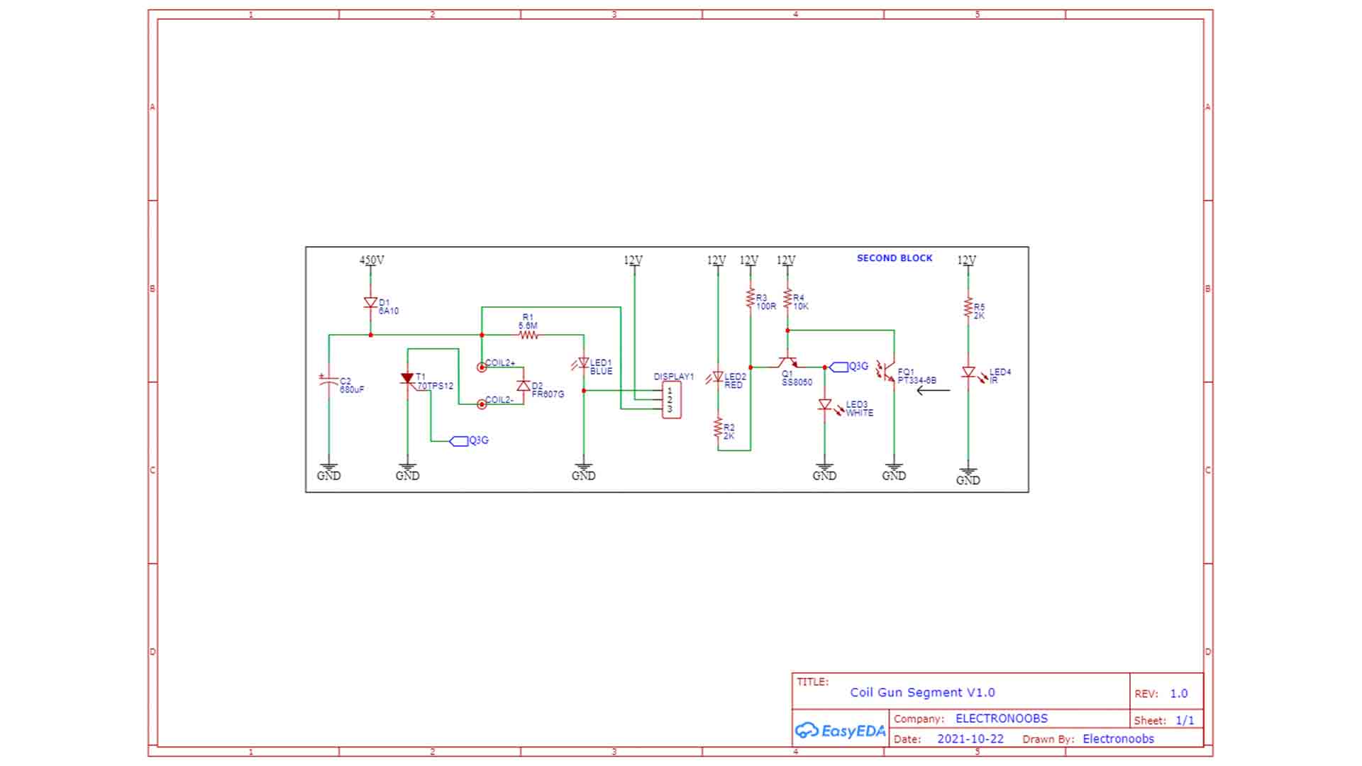
The schematic for the segment is the same but without the first stage controlled by the push button. We can get the signal from the phototransistor detector and apply it to a control circuit that controls a Thyristor. This Thyristor is connected to the coil, so we can turn on and off the power, and with that on and off the magnetic field. When we detect the bullet, we cut off the power so the projectile can continue on the other side. And that’s how is done. The circuit I have for the coil gun segment is something like this below. I have this Thyristor connected to the coil. Its gate is connected to this BJT transistor which is controlled by the infrared sensor output. The circuit is supplied at 450V DC and we will see how to get that voltage in a moment. Since the PCBs have exposed copper pads, we can merge them together and they can share GND and 450V.