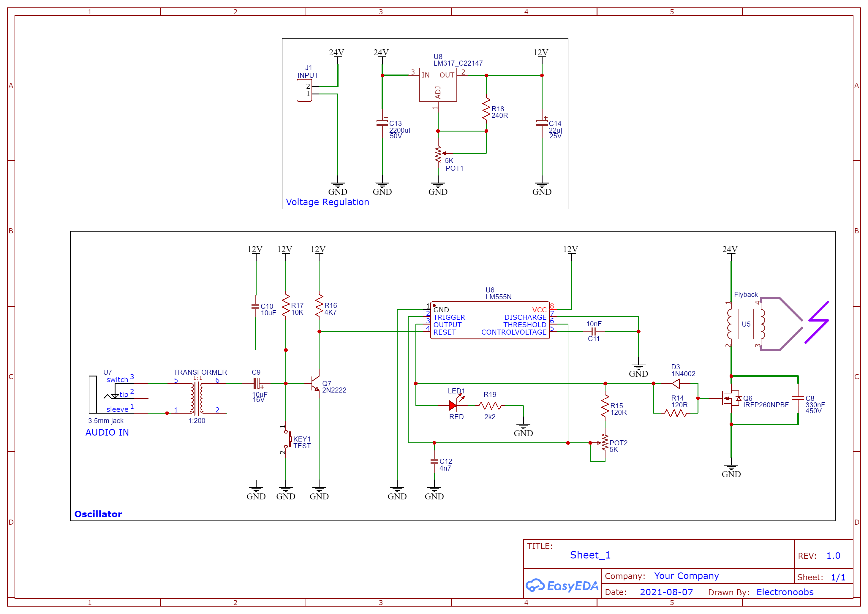

Let’s take a look at the second schematic and this homemade prototype PCB that I’ve made. This circuit is inspired by Franzoli Electronics work. First of all, as you can see I’m now using a huge IGBT and I’ve place it over a big heat dissipator. At such power, the transistor was getting hot in a couple of seconds, very hot, probably more than 100 degrees. We have again a big capacitor of 330nF to oscillate together with the primary coil of the flyback transformer. The main difference for this circuit, is that the music modulation is made with a 555 timer. As you know, this IC will create a square wave and we can change the frequency of that signal using this potentiometer. On top of that, we connect the audio signal to a BJT transistor to invert it and then we control the reset pin of the 555 time, and by that we tell the IC when to enable the high frequency output or not. By that, the output signal will be with the rhythm of the music. The rest of the circuit is just a regulation IC to get 12V from 24V because this circuit works at 24V but we supply the 555 timer with only 12V.
