
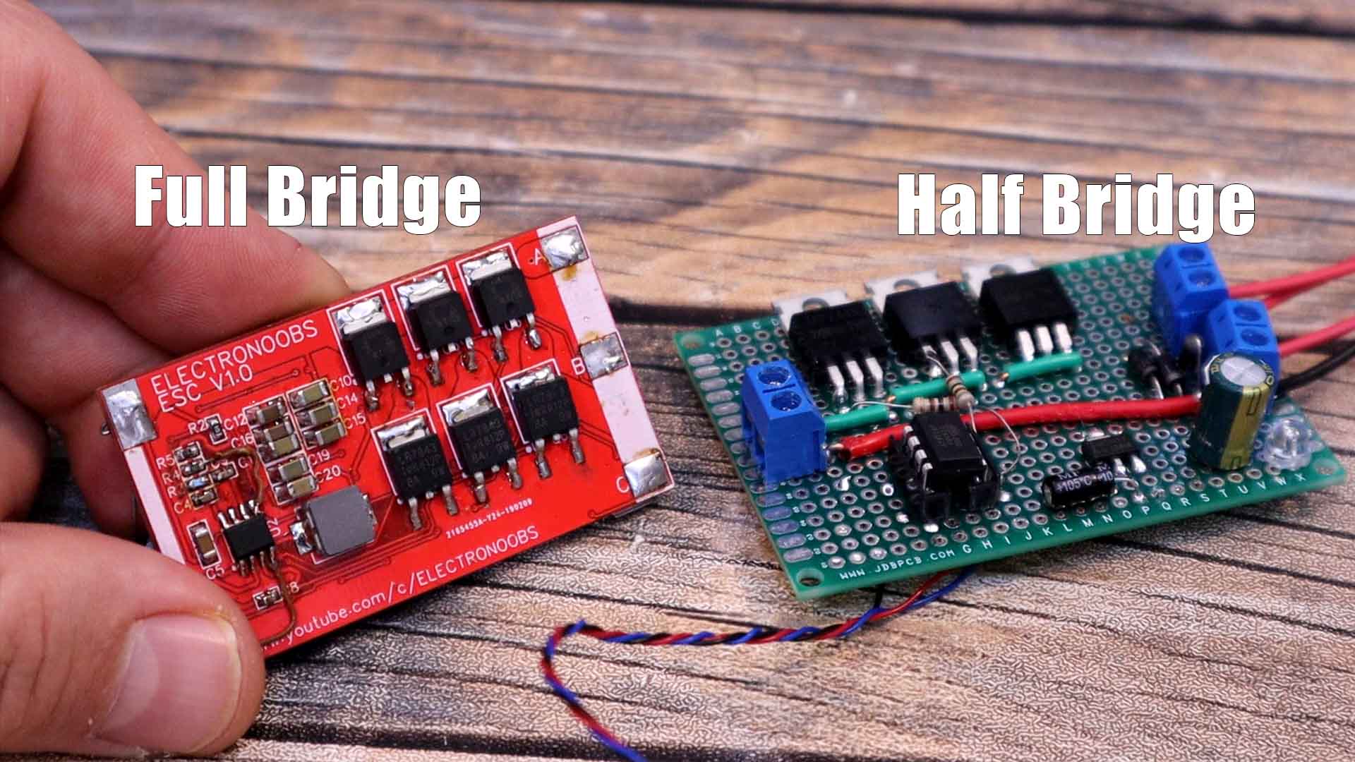
I hope you all remember my open-source ESC design that I’ve made last year and the other versions as well. That one is based on a full triple bridge of MOSFETs and a back EMF closed loop control. This one here for today tutorial, is based on a half bridge control. Basically, half the amount of MOSFETS and half the complexity. This type of ESC only works with those 4 wired brushless motors, meaning we need the 3 phase A, B and C, but also the common point of the star configuration. In this tutorial I will show you this basic half bridge ESC, what’s the deal with that common point on some brushless motors, the components I will use, make the circuit on a PCB and give it a few tests, and I hope you will learn something new. Please have in mind, this circuit has no feedback and is not even close to the results of the full bridge ESC from my previous videos. I'm showing you this circuit just for learning purposes. So guys, let’s get started.
Below you have all the parts needed for this circuit, and on the next step you have the schematic. You can test this circuit on a breadboard or maybe solder it directly to a small prototyping PCB. You can also add an extra LED with a 330 ohm resistor at the AMS117 output, so you can see when the PCB is ON or OFF. Make connections with thick wire so it could handle high current cor the motor. The signal connections could be made with thin wire. Is important to add a big capacior between 12V and gnd near the output.
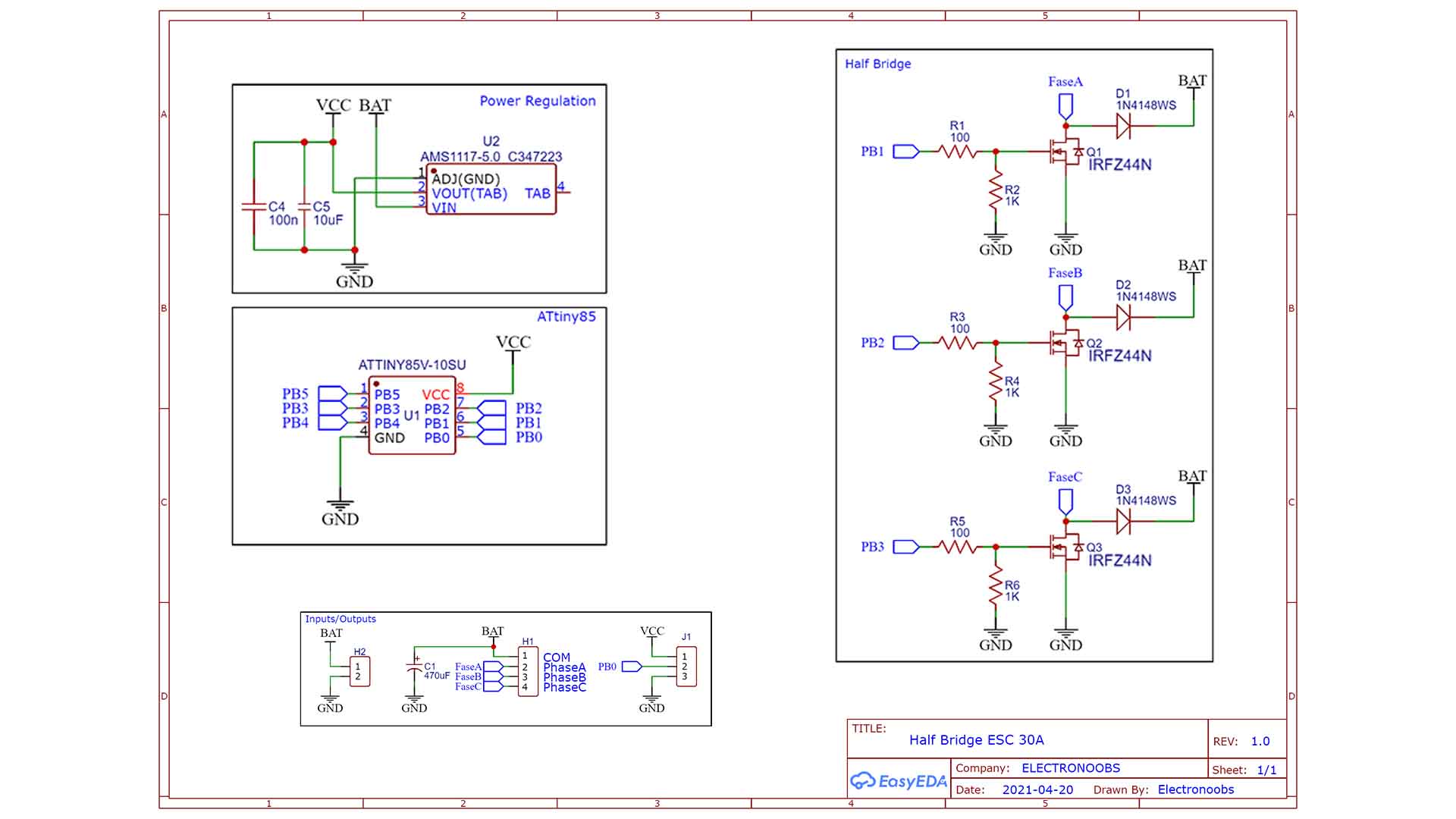
Below you have the schematic I've used. Is very basic and simple. We have 3 N channel MSOFETs connected to ground. Each one has a diode from its drain back to the battery so the current spike from the motors could have a path to flow through and not damage it. Each MSOFET has a pulldown so it would be turned OFF by default. I also add an AMS1117 regulator for 5V and to control the pulse we could use an Arduino, but since this is a very simple design, we can go with a small ATtiny85. To control the speed, we can use a potentiometer for this example but with a more complex code, we could also control the speed with a PWM input.
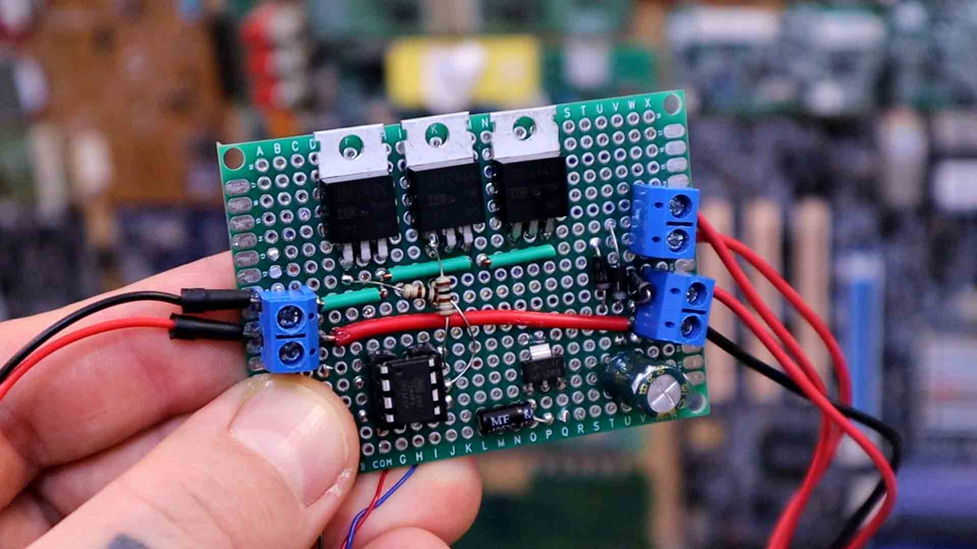
I’ve made all the connections on a prototyping PCB starting with the 3 MOFEST. I've then palced the AMS1117 and made sure that with 12V input I have 5V output. Then I can add the ATtiny. The connections are made with some copper wires on the front and on the back. We also have connections with the small resistors and diodes. I've soldered the potentiometer external to the PCB and I'll use this to adjust the speed. I've used screw terminals fot the battery input and the 4 outputs that go to the motor.
Oh, and by the way, I upload a code to my ATtiny85 using my shield I’ve made in a previous tutorial. So, if you want to know how to make this shield for the Arduino UNO, how to manage the boards in the Arduino IDE and how to upload codes to an ATTINY, see that previous tutorial. In the code, first I define all the variables I use. Then we set the pins for the MSOFET control as outputs and set them to low at the beginning with the registers. In the void loop, we read the voltage from the potentiometer and if it’s over a certain threshold, we activate the rotating sequence. In the sequence, since this is made in open loop control, so we have no feedback, all we do is to switch to high one of the phases, one by one with a small delay in between created by a "if" statement and a counter. But I make another "if" that will chop the pulse in small pulses to also control the power. Basically, that’s it.
//Sequence BAC or CBA or ACB
bool active = false;
unsigned int Delay = 1000;
unsigned int min_delay = 10000;
unsigned int max_delay = 3000;
int duty = 110;
int cycle = 420;
unsigned int actual_time, prev_time, prev_time_2, prev_time_3;
int phase = 0;
bool state = true;

void setup() {
  DDRB |=  B00001110;         //PB1, PB2 and PB3 as OUTPUT
  PORTB &= ~B00001110;        //PB1, PB2 and PB3 to LOW
  DDRB &= ~B00010000;         //PB4 as input (A2)

  actual_time = micros();
  prev_time = actual_time;
  prev_time_2 = actual_time;
  prev_time_3 = actual_time;
}

void loop() {
  int val = analogRead(A2);
  if(val > 100){                                          //Potentiometer threshold
    active = true;
    Delay = map(val, 100, 1024, min_delay, max_delay);    //Map the speed delay
  }
  else if (val < 100){                                    //If below threshold, we turn off all pins.
    active = false;
    PORTB &= ~B00001110;    //PB1, PB2 and PB3 to LOW
  }

  if(active){                                             //If active, we make the rotation loop
    actual_time = micros();
    if(actual_time - prev_time >= Delay){                 //This if creates the delay between each phase
      prev_time += Delay;
      phase++;                                            //Increase the phase to the next
      if(phase > 2){                                      //If phase = 3, we go back to 1 (0 to 2)
        phase = 0;
      }
    }//end of delay

    if(actual_time - prev_time_2 >= cycle){               //This small "if" chops the phase in small pulses
      prev_time_2 = prev_time_2 + cycle;
      if(phase == 0){
        PORTB &= ~B00001100;
        PORTB |=  B00000010;
      }

      else if(phase == 1){
        PORTB &= ~B00001010;
        PORTB |=  B00000100;
      }

      else if(phase == 2){
        PORTB &= ~B00000110;
        PORTB |=  B00001000;
      }
      delayMicroseconds(duty);
      PORTB &= ~B00001110;
    }
  }//end of active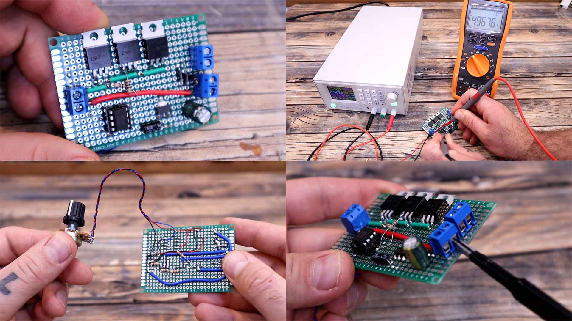
}Now I connect the motor to my board with connections for the 3 phases and the common point. I supply the PCB with 12 volts from my power supply. The PCB automatically starts because it has a voltage regulator for 5V. As you can see, when I increase the potentiometer, the motor starts rotating. Also, I can increase the speed with the potentiometer. Below you can see the signals from each phase on the oscilloscope. We have 3 phases and when one is pulsating, the other two are off. I've stoped the oscilloscope so we can better see each phase. As you can see, the faster the motor spins, the smaller is the delay between the puleses.
So why is the half bridge worst than the full bridge controller? Well, first of all, remember that with the full bridge control, we energize two phases at the same time. One coil has current going in and the other one has current going out and like that is creating two different magnetic fields, one pushing and one pulling. But with the half bridge, we can only energize one phase, so that means less power so less torque. The good thing is that the circuit is way simpler. We don’t have the high side MSOFETs which usually is the one that gives problems and should be made with P-type MSOFETs. We have less components and less signals to control from the microcontroller. But other bad thing about the half bridge configuration, is that we can’t implement the back EMF feedback anymore. Remember that for the virtual zero cross, we need two coils energized and one floating and the sum of all 3 is the virtual 0. This time we can’t do that anymore so the feedback must be made with hall sensors. That means, if I stop the motor with my hand, it won’t start again because it has no feedback and can’t start again by its own. We need to lower the speed and increase it back again slowly.
So guys, that’s how the half bridge controller should work. With a more powerful microcontroller and sensors, we could control the rotation even better but trust me, the full bridge design is a lot better. I do have quite some experience with ESCs, over the last few years I’ve tested many configurations and improved my design more and more from the first PCB that was open loop, had many fails and rotated a very low speeds, the second attempt the prototype for the senosred ESC and closed loop control and after a lot of back EMF testing and code improving, I was able to make my first open-source ESC that was working pretty close to a commercial one.
I hope you like this tutorial and maybe you have learned something new. If my videos help you, consider supporting my work on my PATREON or a donation on my PayPal. Thanks again and see you later guys.


