


We have seen a lot of radio controllers on this channel till now. We’ve seen one using the NRF24 module and making the entire board, weeks back we had the controller made with the HC 12 radio module and a gyro control, but today I have a one of the simplest radio-controller.
This board use a 433Mhz radio connection and an ATTINY 85 chip, so everything is very simple. It has only 4 “digital” channels so we can’t really use it with drones for example. But we could connect anything to these 4 digital outputs. The design is simple and very cheap, just a few dollars.
Let’s start with the ATtiny85 chip. This is an 8-bit RISC microcontroller and sometimes it’s also called a small Arduino. It has 5 IO pins, all 5 can be digital, 3 of them can be analog inputs and two could create PWM signals. To program this chip, we need an SPI communication. My code will use the "micro" function as well, and after searching online, I’ve found that the ATTINY could use those functions only with an 8MHz bootloader. We will reate a shield for the ATtiny85 following the schematic below that can then be connected to an Arduino Uno.
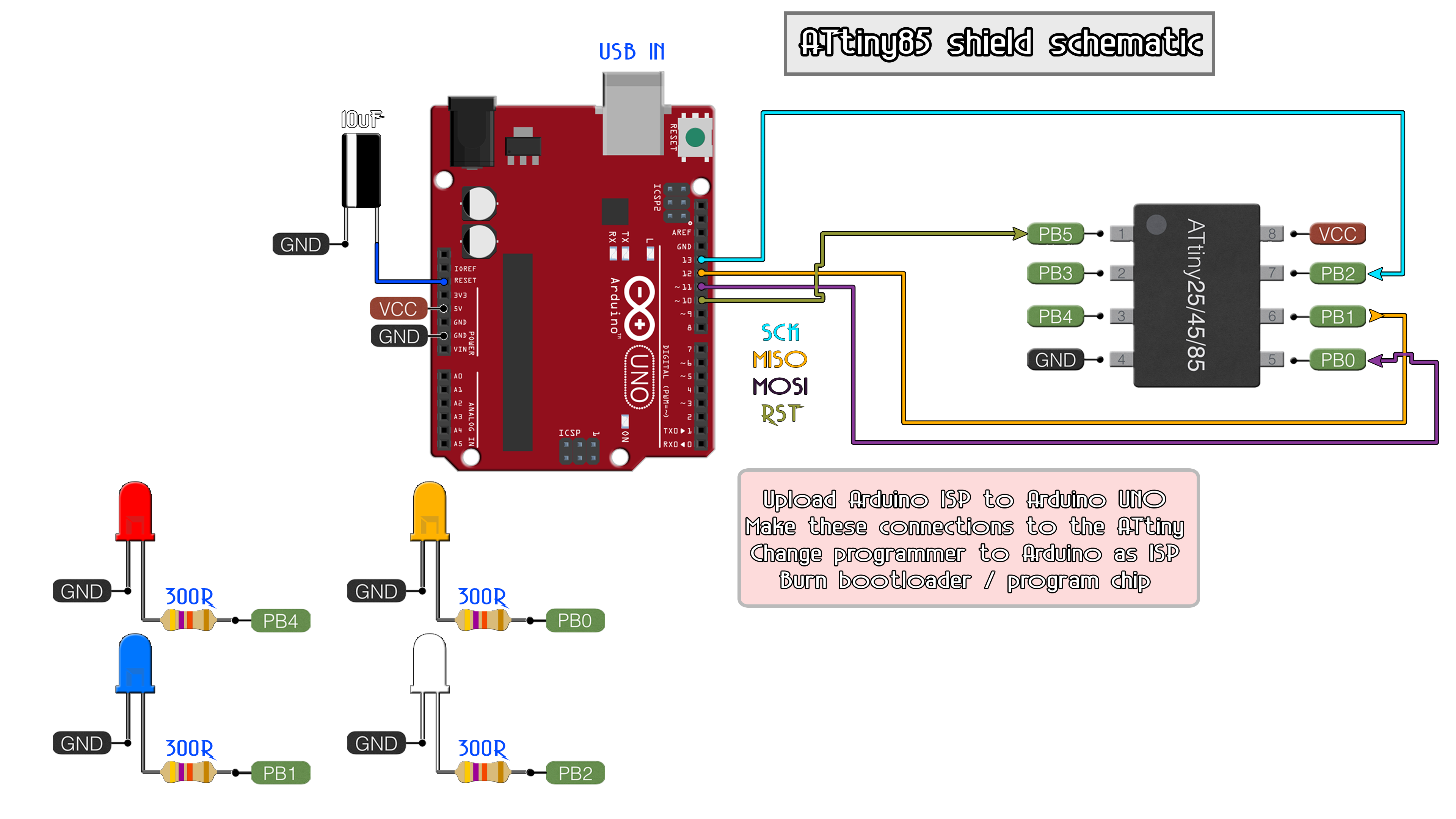
The shield is ready. Plug it into the Arduino UNO and put an ATTINY 85 into the socket. Make sure which is pin one and don’t put the chip reversed. Now connect the Arduino Uno to your PC. Now, pay attention. Right now, I’m using the latest version of the Arduino IDE, which is the 1.8.7. But for some reason the ATtiny85 boards won’t work with this version. For that, go below in the description and download the zip file with the Arduino IDE version 1.0.5.
Extract that in any folder that you want, it doesn’t require installation. I’ve extracted it in program files. Now go below once again and download the attiny master zip file. Open that zip file and copy the tiny folder. Now go to the Arduino 1.0.5 folder, go to hardware, and paste that tiny folder here. Now go back and run Arduino from this folder. With this method we won’t affect the other version of the Arduino that we already have installed.
How, if you go to tools, boards you will see a lot of ATTINY boards. So we are ready.
Ok, so, when I bought the chip, it had a 1MHz internal oscillator bootloader. But we need an 8MHz. for that go to file, examples, Arduino ISP and open that example. Go to boards, and select Arduino UNO, select the com and upload this code to the Arduino. Now we could use the ISP programmer.
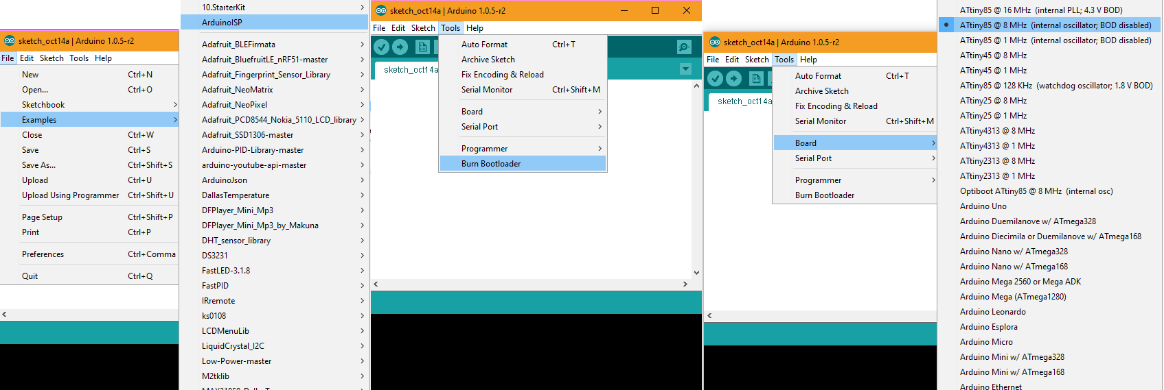
Go back to tools, boards and select ATTINY 85, 8 MHz internal oscillator board. Go once again to tools, programmer, and select Arduino as ISP.
Select tools, and burn bootloader. You will see the LEDs flashing a lot and now the ATTINY 85 has an 8MHz bootloader installed. Is time to program it. Go to example, basic and open the blink example. Change the pin to let’s say digital pin 0 of the ATTINY 85. Make sure you have the ATTINY 85 board selected and click upload. So, there you go, now the LED is blinking with the ATTINY. We don’t need the Arduino anymore.
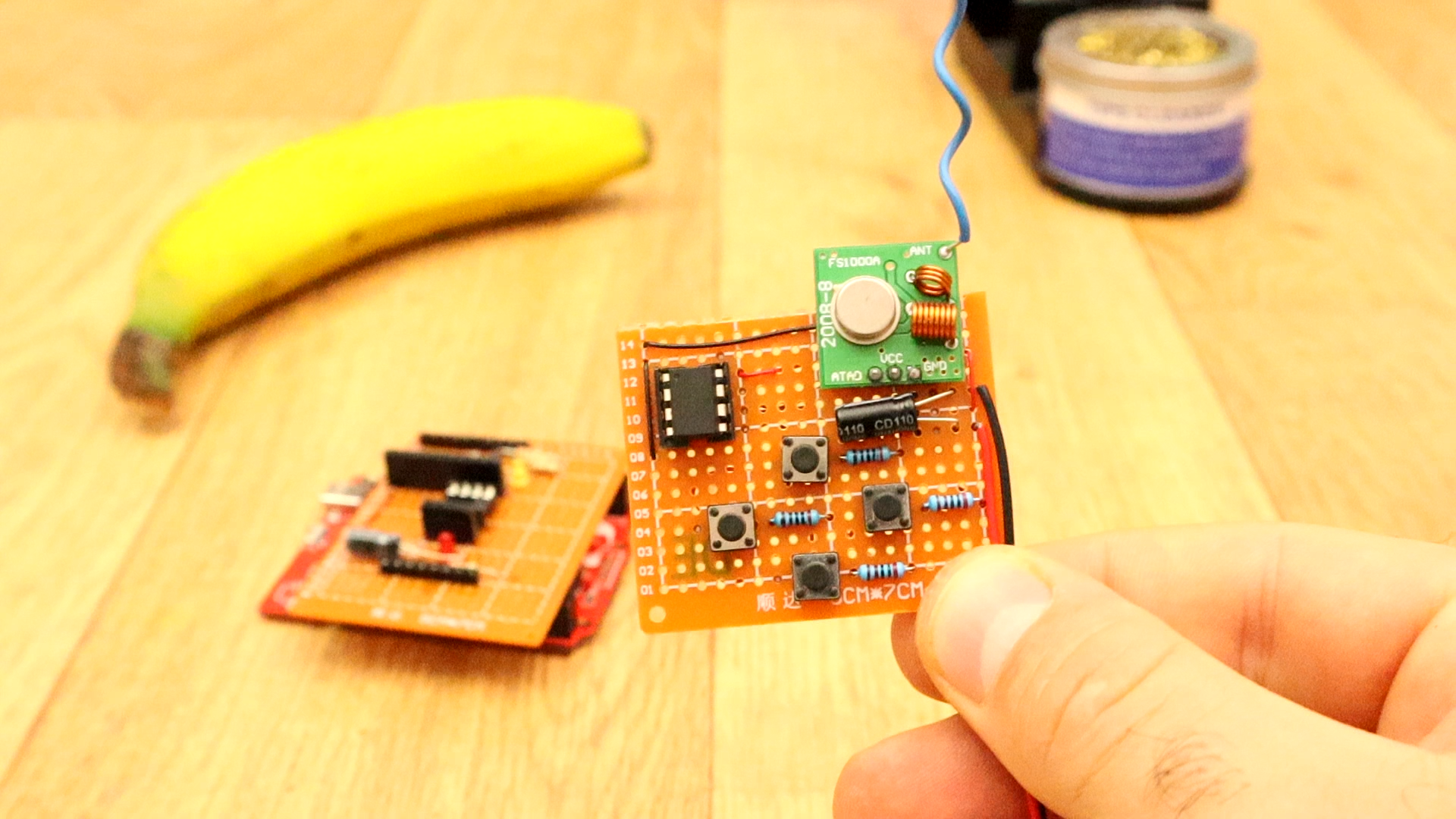
I want a radio connection between two ATTINYs. To keep it simple and cheap, I’ll use two 433MHz modules. I’ve reversed engineered the modules and I’ve made the schematics for both transmitter and receiver and also made my own boards that already include the ATTINY, buttons, and the radio circuits. But first, let’s make this project with the commercial modules that only cost around 50 cents.
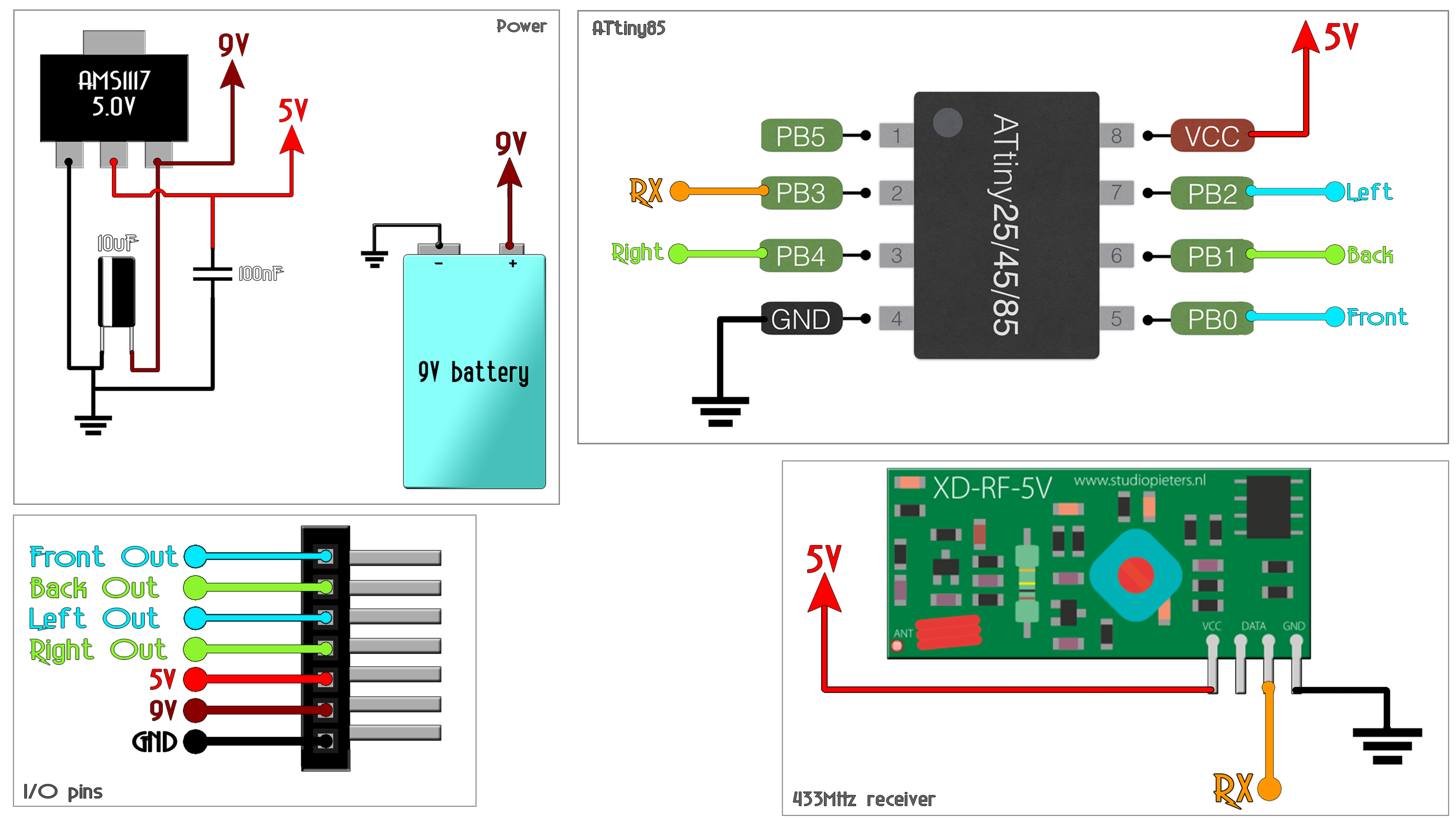
This is the schematic for the transmitter. I’ll have 4 push buttons with pulldowns connected to digital pins 0, 1, 2 and 4 of the ATTINY. Digital pin 3 is the data out pin that goes to the radio transmitter. I’ve also placed an AMS11 17 5V voltage regulator so I could supply the board using a 9V battery. Later I’ve also placed and LED to notify me when the transmitter os powered on and alos a slidwing stitch.
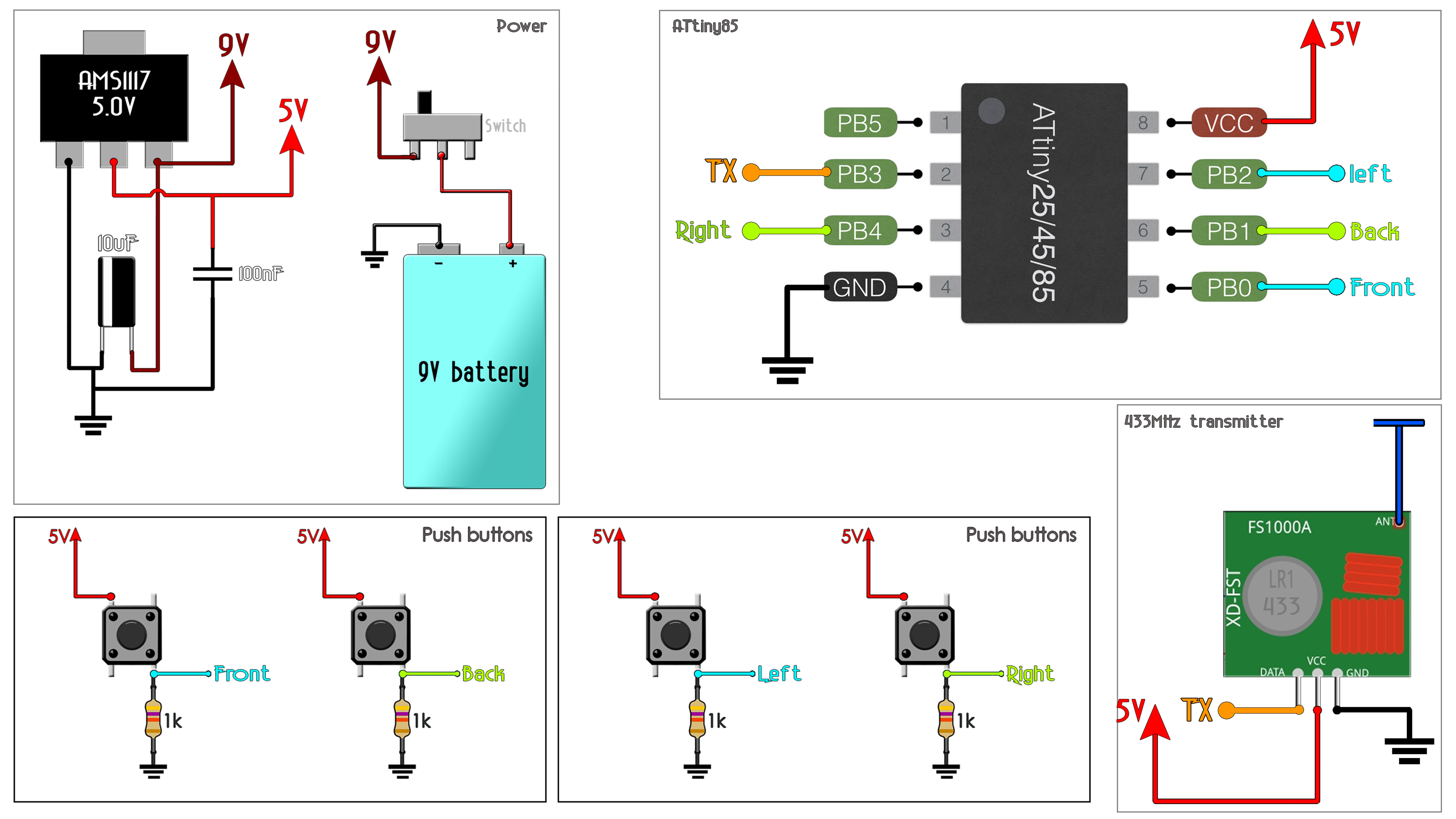
I’ve made the connections on a drilled PCB with sockets for the ATTINY chips and I also solder a wire to the transmitter module as an antenna to increase range. Remember that these modules are not for long range. A maximum of 100 meters using antennas.
This is the schematic for the receiver. This is the board I’ve made for the receiver, it has the ATTINY, the radio receiver, the 5V regulatotr and pins fot input power and output for 4 channels. The outputs could be connected to anything. In this case I’ll later connect some LEDs to show you the results. Pin D3 is the data in from the radio receiver and the receiver board is ready.
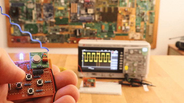
Ok guys, these modules work fine using virtual wire. With Arduino that worked fine, you have a tutorial about this on my webpage. I’ve even made a chat between two arduinos using this modules. But, for some reason, using the ATTINYs, I couldn’t manage to get to work the virtual wire communication. So, I decided to keep it even simple. This is what I do. I create a square wave on the transmitter pin. Depending on which button is pressed, I will change the frequency of that square signal. On the receiver, I measure the frequency, and depending the value, I activate one or other output. Here I have the receiver signal connected to my oscilloscope. As you can see, for each button I have a different frequency and all I have to do now is to detect the range.
That’s it. Upload the codes as before using the Arduino UNO shield and we are ready. As you can see, now, for each button pressed, a different LED is turned on. The downside of this controller is that it only has digital channels. If you want analog signals. You should change the transmitted signal and use some kind of encoding system.


