
This MCP4725 is a DAC module, or digital to analog converter. As its name implies, this module could create analog voltages and we can set the output values using digital numbers. The Arduino for example, doesn’t have a DAC, only ADCs. That’s why this module is great in order to have a steady DC output. You will see that it’s also capable of generating signals, so that’s also interesting. So Stick around in order to learn more about this module and how to use it. So guys, let’s get started.
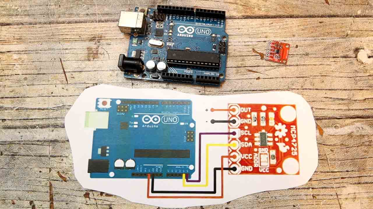
This is the MCP4725 module and this is a DAC or digital to analog converter. It means that we can send digital instructions to it and it will output a steady DC value. But it could also create analog signals such as a sine wave, sawtooth, triangle or square signals, so it could be just like a small function generator but as we will see later it has its limitations. So, this works with i2c communication. So we connect the SCL and SDA pins for clock and data to the pins of the Arduino, pins A4 and A5 as always. The module works at 5V so we also connect the supply and ground from the Arduino. On the out pins we will get the output.
Go to sketch, include library and open the library manager. There search for MCP4725 and select the Adafruit library and install it. Or you could download it from below and install it as a ZIP file. Then download or copy from below this first example code. As you can see in the code, we import the needed library. Then we start an i2c communication with the 0x60 address because my module has the ADDR pin connected to ground. Then we use the set voltage function to set the output to 1, 2, 3, 4 and 5 volts with a 2 seconds delay in between. Upload this code to the Arduino and connect a multimeter at the output.
#include <Wire.h>
#include <Adafruit_MCP4725.h>
Adafruit_MCP4725 dac;
// Set this value to 9, 8, 7, 6 or 5 to adjust the resolution
#define DAC_RESOLUTION    (9)

void setup(void) {
  Serial.begin(9600);
  Serial.println("MCP4725A1 Test");
  // MCP4725A1 address is 0x62 (default)
  // MCP4725A1 address is 0x63 (ADDR pin tied to VCC)
  // MCP4725A1 address is 0x60 (ADDR pin tied to GND)
  dac.begin(0x60); //I have my ADDR pin connected to GND so address is 0x60
}

void loop(void) {
  dac.setVoltage((1*4095)/5, false);        //Set voltage to 1V
  delay(2000);
  dac.setVoltage((2*4095)/5, false);        //Set voltage to 2V
  delay(2000);
  dac.setVoltage((3*4095)/5, false);        //Set voltage to 3V
  delay(2000);
  dac.setVoltage((4*4095)/5, false);        //Set voltage to 4V
  delay(2000);
  dac.setVoltage(4095, false);              //Set voltage to 5V or (Vcc)
  delay(2000);
}Now let’s see another example generating signals. This below is the code for that, and as you can see, we now create a lookup table with the values for our signal. One is for a sine wave of 9 bits, another one is for 8 bits, 7 bits and so on. If we check check the result on the oscilloscope with a resolution of 9 bits you can see the signal is very smooth. Only if we zoom in almost to the maximum we can see some small steps. If we make the same with only 5 bits you would see that the values vector has only 32 different steps. With fewer bits, is obvious that we can see the steps of the DAC. But on the other side, with 9 bits it was practically a perfect sine wave and we can’t see any steps. But anyway, we can always add a capacitor at the output to smooth the steps a little bit.
#include <Wire.h>
#include <Adafruit_MCP4725.h>

Adafruit_MCP4725 dac;

// Set this value to 9, 8, 7, 6 or 5 to adjust the resolution
#define DAC_RESOLUTION    (9)

const PROGMEM uint16_t DACLookup_FullSine_9Bit[512] =
{
  2048, 2073, 2098, 2123, 2148, 2174, 2199, 2224,
  2249, 2274, 2299, 2324, 2349, 2373, 2398, 2423,
  2448, 2472, 2497, 2521, 2546, 2570, 2594, 2618,
  2643, 2667, 2690, 2714, 2738, 2762, 2785, 2808,
  2832, 2855, 2878, 2901, 2924, 2946, 2969, 2991,
  3013, 3036, 3057, 3079, 3101, 3122, 3144, 3165,
  3186, 3207, 3227, 3248, 3268, 3288, 3308, 3328,
  3347, 3367, 3386, 3405, 3423, 3442, 3460, 3478,
  3496, 3514, 3531, 3548, 3565, 3582, 3599, 3615,
  3631, 3647, 3663, 3678, 3693, 3708, 3722, 3737,
  3751, 3765, 3778, 3792, 3805, 3817, 3830, 3842,
  3854, 3866, 3877, 3888, 3899, 3910, 3920, 3930,
  3940, 3950, 3959, 3968, 3976, 3985, 3993, 4000,
  4008, 4015, 4022, 4028, 4035, 4041, 4046, 4052,
  4057, 4061, 4066, 4070, 4074, 4077, 4081, 4084,
  4086, 4088, 4090, 4092, 4094, 4095, 4095, 4095,
  4095, 4095, 4095, 4095, 4094, 4092, 4090, 4088,
  4086, 4084, 4081, 4077, 4074, 4070, 4066, 4061,
  4057, 4052, 4046, 4041, 4035, 4028, 4022, 4015,
  4008, 4000, 3993, 3985, 3976, 3968, 3959, 3950,
  3940, 3930, 3920, 3910, 3899, 3888, 3877, 3866,
  3854, 3842, 3830, 3817, 3805, 3792, 3778, 3765,
  3751, 3737, 3722, 3708, 3693, 3678, 3663, 3647,
  3631, 3615, 3599, 3582, 3565, 3548, 3531, 3514,
  3496, 3478, 3460, 3442, 3423, 3405, 3386, 3367,
  3347, 3328, 3308, 3288, 3268, 3248, 3227, 3207,
  3186, 3165, 3144, 3122, 3101, 3079, 3057, 3036,
  3013, 2991, 2969, 2946, 2924, 2901, 2878, 2855,
  2832, 2808, 2785, 2762, 2738, 2714, 2690, 2667,
  2643, 2618, 2594, 2570, 2546, 2521, 2497, 2472,
  2448, 2423, 2398, 2373, 2349, 2324, 2299, 2274,
  2249, 2224, 2199, 2174, 2148, 2123, 2098, 2073,
  2048, 2023, 1998, 1973, 1948, 1922, 1897, 1872,
  1847, 1822, 1797, 1772, 1747, 1723, 1698, 1673,
  1648, 1624, 1599, 1575, 1550, 1526, 1502, 1478,
  1453, 1429, 1406, 1382, 1358, 1334, 1311, 1288,
  1264, 1241, 1218, 1195, 1172, 1150, 1127, 1105,
  1083, 1060, 1039, 1017,  995,  974,  952,  931,
   910,  889,  869,  848,  828,  808,  788,  768,
   749,  729,  710,  691,  673,  654,  636,  618,
   600,  582,  565,  548,  531,  514,  497,  481,
   465,  449,  433,  418,  403,  388,  374,  359,
   345,  331,  318,  304,  291,  279,  266,  254,
   242,  230,  219,  208,  197,  186,  176,  166,
   156,  146,  137,  128,  120,  111,  103,   96,
    88,   81,   74,   68,   61,   55,   50,   44,
    39,   35,   30,   26,   22,   19,   15,   12,
    10,    8,    6,    4,    2,    1,    1,    0,
     0,    0,    1,    1,    2,    4,    6,    8,
    10,   12,   15,   19,   22,   26,   30,   35,
    39,   44,   50,   55,   61,   68,   74,   81,
    88,   96,  103,  111,  120,  128,  137,  146,
   156,  166,  176,  186,  197,  208,  219,  230,
   242,  254,  266,  279,  291,  304,  318,  331,
   345,  359,  374,  388,  403,  418,  433,  449,
   465,  481,  497,  514,  531,  548,  565,  582,
   600,  618,  636,  654,  673,  691,  710,  729,
   749,  768,  788,  808,  828,  848,  869,  889,
   910,  931,  952,  974,  995, 1017, 1039, 1060,
  1083, 1105, 1127, 1150, 1172, 1195, 1218, 1241,
  1264, 1288, 1311, 1334, 1358, 1382, 1406, 1429,
  1453, 1478, 1502, 1526, 1550, 1575, 1599, 1624,
  1648, 1673, 1698, 1723, 1747, 1772, 1797, 1822,
  1847, 1872, 1897, 1922, 1948, 1973, 1998, 2023
};

void setup(void) {
// For Adafruit MCP4725A1 the address is 0x62 (default) or 0x63 (ADDR pin tied to VCC)
  // For MCP4725A0 the address is 0x60 or 0x61
  // For MCP4725A2 the address is 0x64 or 0x65
  dac.begin(0x60);  //My ADDR pin is connected to GND
}

void loop(void) {
  uint16_t i;
  for (i = 0; i < 512; i++)
    {
      dac.setVoltage(pgm_read_word(&(DACLookup_FullSine_9Bit[i])), false);
    }
}Now let’s make another code. This time we read the input from a potentiometer and create a delay. Varying this delay, we can change the frequency of the signal. Upload the code below and add a potentiometer to analog input pin A0 and a push button to digital pin D2. As you can see we can now change the frequency as well. Also if I push the button, we can change the signal type from sine, to triangle or sawtooth. One thing that you can notice is that the maximum frequency is only 62 Hertz. That’s very, very slow for a function generator, right? The i2c communication of the module works at 400Khz, but even so, because we need to send so many bits, and so many values for each wave, limits the maximum frequency. But anyway, at a lower resolution we can get to higher speeds than only 62Hz.
#include <Wire.h>
#include <Adafruit_MCP4725.h>
int signals = 0;
int freq = 0;

Adafruit_MCP4725 dac;

const PROGMEM uint16_t DACLookup_Sine_100[100] =
{
 2048, 2176, 2304, 2431, 2557, 2680, 2801, 2919,
 3034, 3145, 3251, 3353, 3449, 3540, 3625, 3704,
 3776, 3842, 3900, 3951, 3995, 4031, 4059, 4079,
 4091, 4095, 4091, 4079, 4059, 4031, 3995, 3951,
 3900, 3842, 3776, 3704, 3625, 3540, 3449, 3353,
 3251, 3145, 3034, 2919, 2801, 2680, 2557, 2431,
 2304, 2176, 2048, 1919, 1791, 1664, 1538, 1415,
 1294, 1176, 1061,  950,  844,  742,  646,  555,
  470,  391,  319,  253,  195,  144,  100,   64,
   36,   16,    4,    0,    4,   16,   36,   64,
  100,  144,  195,  253,  319,  391,  470,  555,
  646,  742,  844,  950, 1061, 1176, 1294, 1415,
 1538, 1664, 1791, 1919
};

const PROGMEM uint16_t DACLookup_Triangle_100[100] =
{
    0,   82,  164,  246,  328,  410,  491,  573,
  655,  737,  819,  901,  983, 1065, 1147, 1229,
 1310, 1392, 1474, 1556, 1638, 1720, 1802, 1884,
 1966, 2048, 2129, 2211, 2293, 2375, 2457, 2539,
 2621, 2703, 2785, 2867, 2948, 3030, 3112, 3194,
 3276, 3358, 3440, 3522, 3604, 3686, 3767, 3849,
 3931, 4013, 4095, 4013, 3931, 3849, 3767, 3686,
 3604, 3522, 3440, 3358, 3276, 3194, 3112, 3030,
 2948, 2867, 2785, 2703, 2621, 2539, 2457, 2375,
 2293, 2211, 2129, 2048, 1966, 1884, 1802, 1720,
 1638, 1556, 1474, 1392, 1310, 1229, 1147, 1065,
  983,  901,  819,  737,  655,  573,  491,  410,
  328,  246,  164,   82
};

const PROGMEM uint16_t DACLookup_Saw_100[100] =
{
    0,   41,   82,  123,  164,  205,  246,  287,
  328,  369,  410,  451,  491,  533,  573,  615,
  655,  697,  737,  779,  819,  861,  901,  943,
  983, 1025, 1065, 1107, 1147, 1189, 1229, 1271,
 1310, 1353, 1392, 1433, 1474, 1515, 1556, 1597,
 1638, 1679, 1720, 1761, 1802, 1843, 1884, 1925,
 1966, 2007, 2048, 2089, 2129, 2171, 2211, 2253,
 2293, 2334, 2375, 2416, 2457, 2498, 2539, 2580,
 2621, 2662, 2703, 2744, 2785, 2826, 2867, 2908,
 2948, 2989, 3030, 3071, 3112, 3153, 3194, 3235,
 3276, 3317, 3358, 3399, 3440, 3481, 3522, 3563,
 3604, 3645, 3686, 3727, 3767, 3809, 3849, 3891,
 3931, 3973, 4013, 4095
};

void setup(void){
   dac.begin(0x60);                                             //My ADDR pin is connected to GND so address is 0x60
   pinMode(2, INPUT_PULLUP);
   attachInterrupt(digitalPinToInterrupt(2), change_type, LOW); // Connect button on D2
}

void SINE(void){
   uint16_t i;
   for(i = 0; i < 100; i++){
      dac.setVoltage(pgm_read_word(&(DACLookup_Sine_100[i])), false);
      delayMicroseconds(freq);
   }
}

void TRIANGLE(void){
   uint16_t i;
   for(i = 0; i < 100; i++){
      dac.setVoltage(pgm_read_word(&(DACLookup_Triangle_100[i])), false);
      delayMicroseconds(freq);
   }
}

void SAWTOOTH(void){
   uint16_t i;
   for(i = 0; i < 100; i++){
      dac.setVoltage(pgm_read_word(&(DACLookup_Saw_100[i])), false);
      delayMicroseconds(freq);
   }
}

void change_type(void){
   if(signals < 4 )
      signals ++;
   if(signals ==3)
      signals =0;
}

void loop(void){
   freq = analogRead(A0)+1;
   switch(signals){
   case 0:
      SINE();
      break;
   case 1:
      TRIANGLE();
      break;
   case 2:
      SAWTOOTH();
      break;
   default:
      break;
   }
}Well guys, that’s how you can use the MCP4725 DAC module. You have the example codes and the library above ready to download. hope that you have learned something new and if my videos help you, consider supporting my work on my PATREON or a donation on my PayPal. Thanks again and see you later guys.


