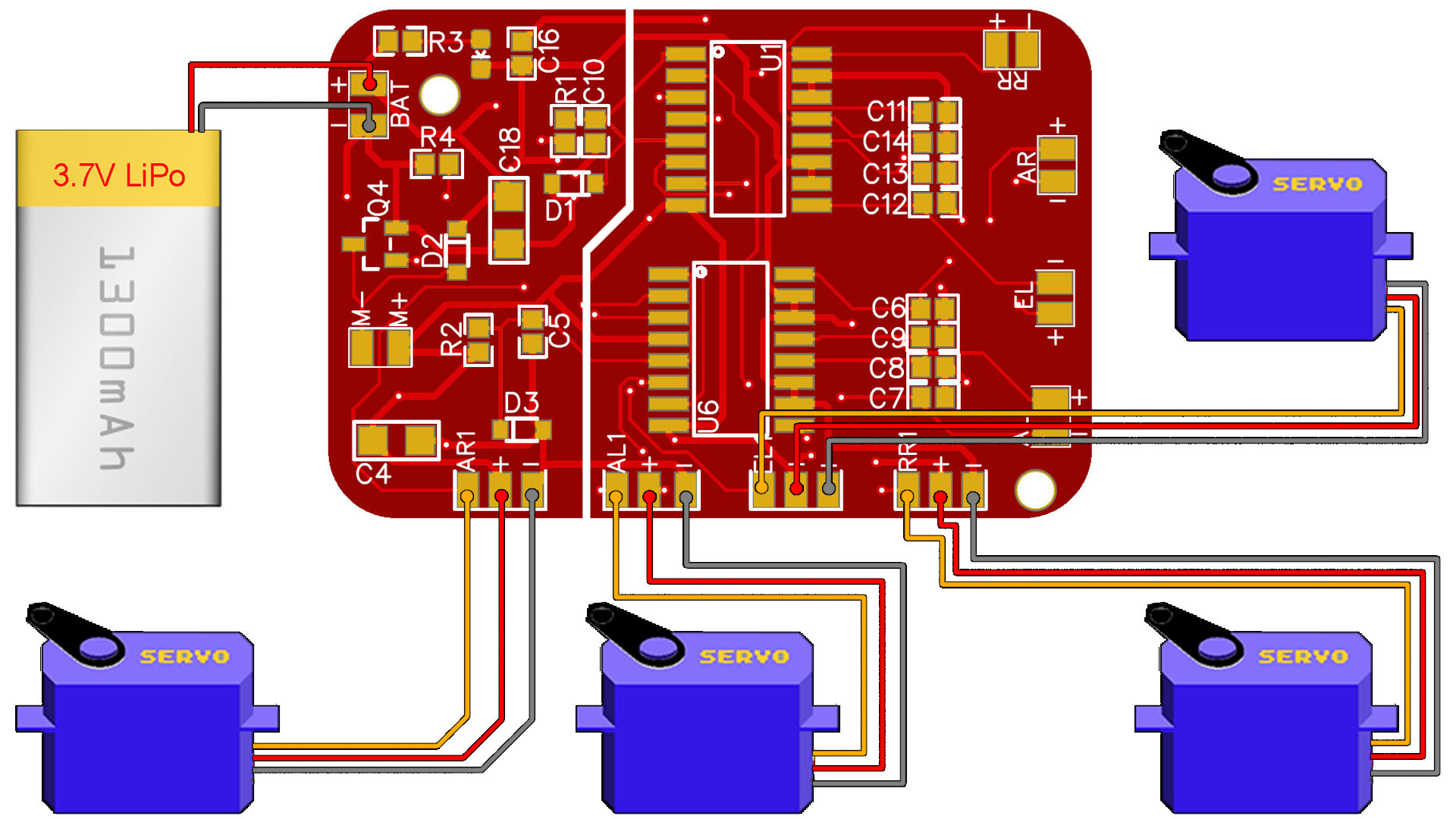
In the video the PCB doesn't have the servo pads but I've made a simple test with some wires connected to the pins. But now, I've cahnged the PCB to have the servo pads for signal, GND and Vcc. So, get the final GERBER file of the PCB from here, order to JLCPCB and get the board. Then, download this second code and upload it to the board using the FTDI programmer and see how to control servos. Remember to haev the same radio controller as in the past tutorial based on Arduino and the NRF24 radio mdoule and use the same pipe code: pipeIn = 0xE8E8F0F0E1LL.
SERVO_AR1.attach(2);
  SERVO_AL1.attach(5);
  SERVO_EL1.attach(9);
  SERVO_RR1.attach(A0);
  SERVO_AR1.writeMicroseconds(1500);  // set servo to mid-point
  SERVO_AL1.writeMicroseconds(1500);  // set servo to mid-point
  SERVO_EL1.writeMicroseconds(1500);  // set servo to mid-point
  SERVO_RR1.writeMicroseconds(1500);  // set servo to mid-point
  .
  .
  .
I hope you will like this simple tutorial. make sure you check all the scheamtics, codes, and also the past tutorial on the Arduino based radio trasnmitter with the NRF24 radio module, because you will need that for this tutorial. Consider supporting my work on PATREON.