
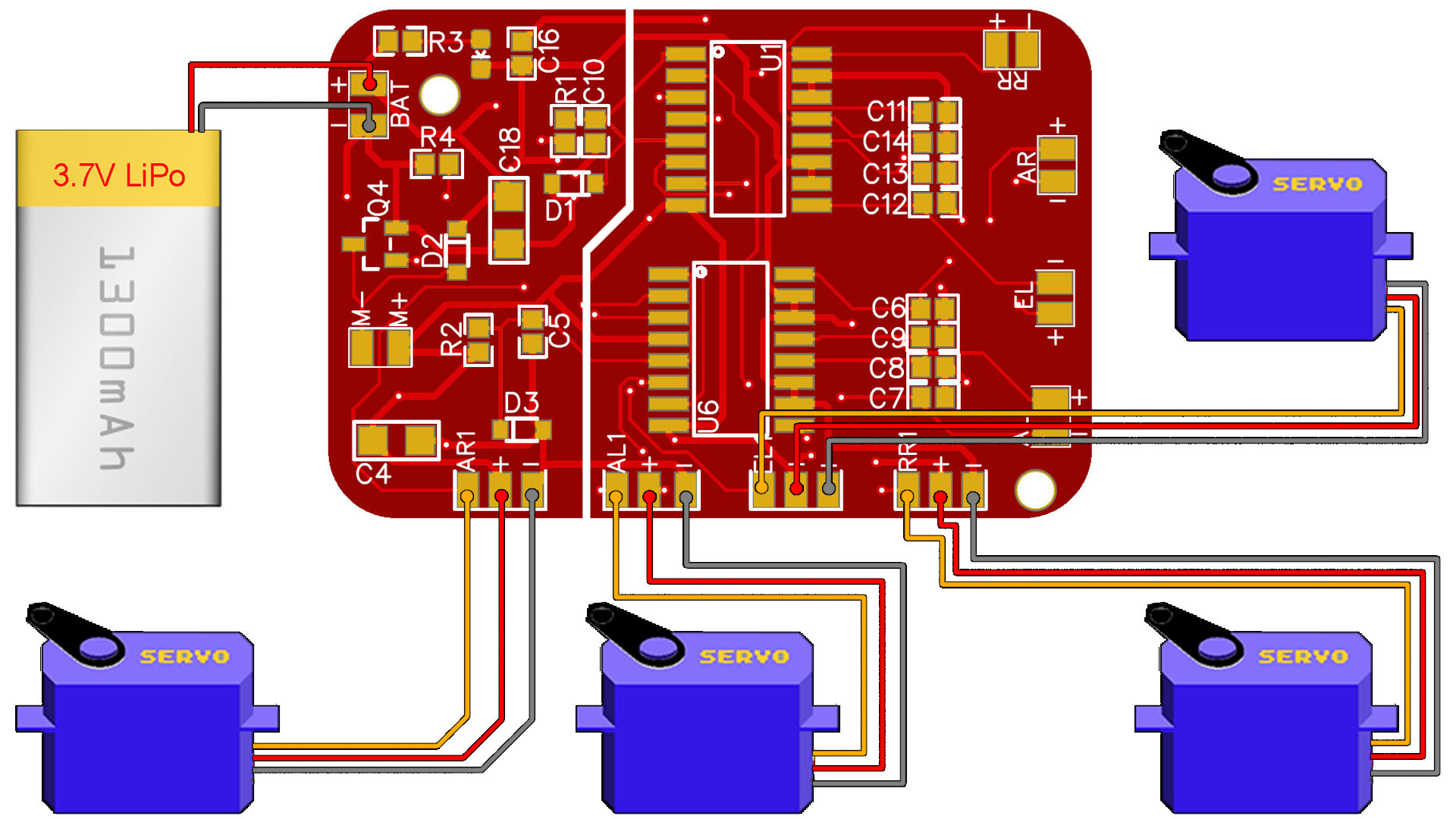
This is the code for the second test of this Tiny receiver PCB with servos. In the video the PCB doesn't have the servo pads but I've made a simple test with some wires connected to the pins. But now, I've cahnged the PCB to have the servo pads for signal, GND and Vcc. So, get the final GERBER file of the PCB from here, order to JLCPCB and get the board. Then, download this second code and upload it to the board using the FTDI programmer and see how to control servos. Remember to haev the same radio controller as in the past tutorial based on Arduino and the NRF24 radio mdoule and use the same pipe code: pipeIn = 0xE8E8F0F0E1LL. Remember to downlaod and install the NRF24 library to your IDE.
/* Test code for the Radio control receiver with servos
 * Install the NRF24 library to your IDE
 * Upload this code to the Tiny receiver PCB
 * Connect a NRF24 module to it:
 * Tutorial: https://electronoobs.com/eng_arduino_tut105.php
 * Scheamtic: https://electronoobs.com/images/Arduino/tut_105/sch_3.jpg
 * Code: https://electronoobs.com/eng_arduino_tut105_code2.php
 * Transmitter tutorial: https://electronoobs.com/eng_arduino_tut86.php

    Module // Arduino UNO
    GND    ->   GND
    Vcc    ->   3.3V
    CE     ->   D7
    CSN    ->   D8
    CLK    ->   D13
    MOSI   ->   D11
    MISO   ->   D12

Please, like share and subscribe : https://www.youtube.com/c/ELECTRONOOBS
*/

#include <SPI.h>
#include <nRF24L01.h>   //Download it here: https://electronoobs.com/eng_arduino_NRF24_lib.php
#include <RF24.h>
#include <Servo.h>      //To create PWM signals we need this lybrary

const uint64_t pipeIn = 0xE8E8F0F0E1LL; //Remember that this code is the same as in the transmitter
RF24 radio(7, 8);

//We could use up to 32 channels
struct MyData {
byte throttle; //We define each byte of data input, in this case just 6 channels
byte yaw;
byte pitch;
byte roll;
byte AUX1;
byte AUX2;
};

MyData data;

void resetData()
{
//We define the inicial value of each data input
//3 potenciometers will be in the middle position so 127 is the middle from 254
data.throttle = 0;
data.yaw = 127;
data.pitch = 127;
data.roll = 127;
data.AUX1 = 0;
data.AUX2 = 0;

}

Servo SERVO_AR1;
Servo SERVO_AL1;
Servo SERVO_EL1;
Servo SERVO_RR1;


/**************************************************/

void setup()
{
  //Select pins for the servos (see PCB)
  SERVO_AR1.attach(2);
  SERVO_AL1.attach(5);
  SERVO_EL1.attach(9);
  SERVO_RR1.attach(A0);
  SERVO_AR1.writeMicroseconds(1500);  // set servo to mid-point
  SERVO_AL1.writeMicroseconds(1500);  // set servo to mid-point
  SERVO_EL1.writeMicroseconds(1500);  // set servo to mid-point
  SERVO_RR1.writeMicroseconds(1500);  // set servo to mid-point

  Serial.begin(9600); //Set the speed to 9600 bauds if you want.
  //You should always have the same speed selected in the serial monitor
  resetData();
  radio.begin();
  radio.setAutoAck(false);
  radio.setDataRate(RF24_250KBPS);

  radio.openReadingPipe(1,pipeIn);
  //we start the radio comunication
  radio.startListening();
}

/**************************************************/

unsigned long lastRecvTime = 0;

void recvData()
{
while ( radio.available() ) {
radio.read(&data, sizeof(MyData));
lastRecvTime = millis(); //here we receive the data
}
}

/**************************************************/

void loop()
{
recvData();
unsigned long now = millis();
//Here we check if we've lost signal, if we did we reset the values
if ( now - lastRecvTime > 1000 ) {
// Signal lost?
resetData();
}


int angle_aleron1 = map(data.yaw, 0,255,700,2300);
int angle_aleron2 = map(data.yaw, 0,255,2300,700);
int angle_rudder = map(data.pitch, 0,255,700,2300);
int angle_elevator = map(data.pitch, 0,255,2300,700);


SERVO_AL1.writeMicroseconds(angle_aleron1);
SERVO_AR1.writeMicroseconds(angle_aleron2);
SERVO_EL1.writeMicroseconds(angle_rudder);
SERVO_RR1.writeMicroseconds(angle_elevator);

//Uncomment below for debug
/*
Serial.print("Throttle: "); Serial.print(data.throttle);  Serial.print("   ");
Serial.print("Yaw: "); Serial.print(data.yaw);  Serial.print("   ");
Serial.print("Pitch: "); Serial.print(data.pitch);  Serial.print("   ");
Serial.print("Roll: "); Serial.print(data.roll);  Serial.print("\n");
*/
}//end void loop

/**************************************************/


