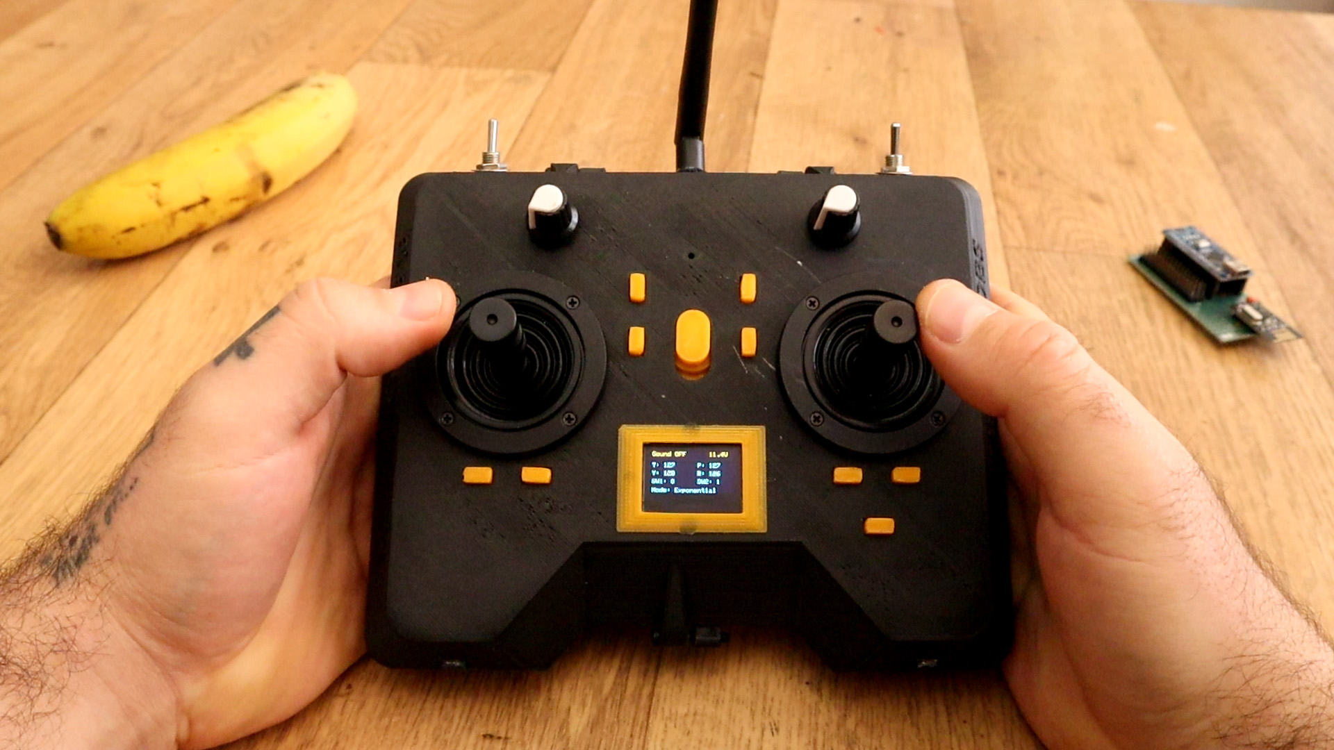
Yes, I've made another radio controller. Why? well, I wanted to have a more commercial look. So, I've designed a 3D case, then I've used some high quality joysticks in order to have better analog read, It has an OLED screen so we could see the data we send and we could also digitally adjust the data. It also has 2 modes, linear and exponential.
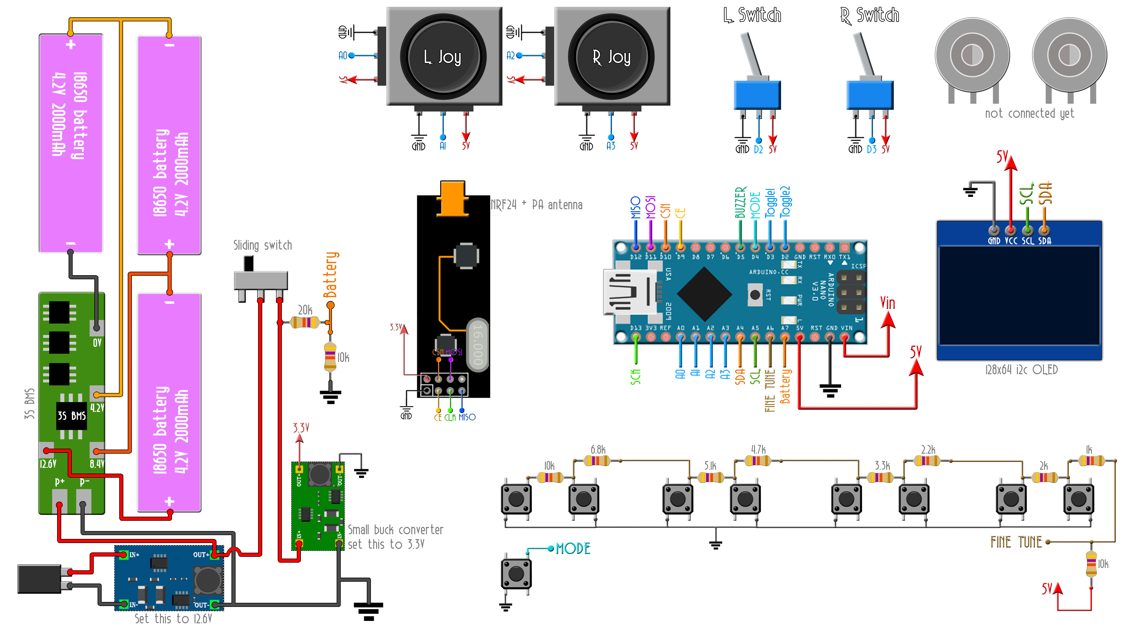
Below you ahve the schematic for this project with all the connections and components values. Check all you need for this porject on the full part list below as well. Make sure you set the buck converters to 12.6V and 3.3V befor you connect them to the circuit.
The case is made out of 2 main parts, the top and bottom part. Then we need 9 plastic push buttons, 4 push button double support and one single support. We also need the sliding switch button. To close the case I've sued 3 3mm screws, two on the top part and one more on the bottom.
I've used 2 perimeters and 20% infill for all the parts and PLA material. There's no need for supports. The parts are already oriented and ready to print. My printer has a 0.4mm nozzle, and the layer height was set to 0.3mm.
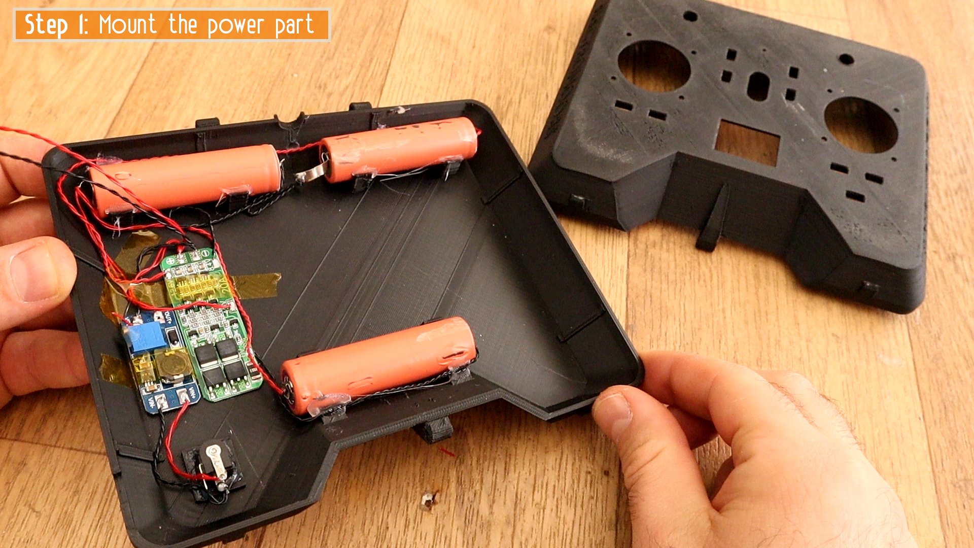
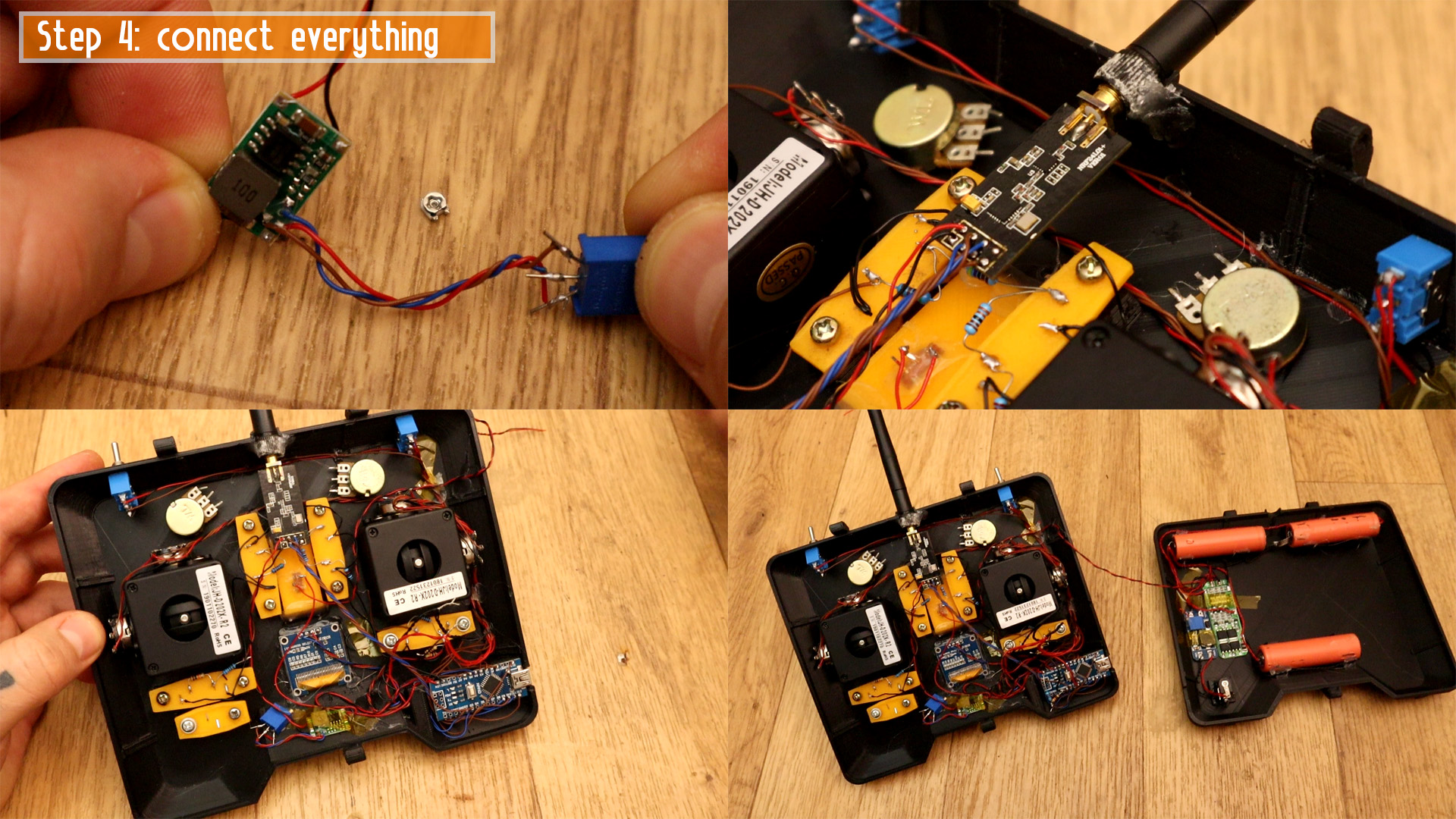
First, I connect in series the batteries and glue them to the back part of the radio controller. Then I solder wires from the DC jack to the big boost/buck converter and I plug in the main adaptor. Then I set the converter to 12.6V and glue the potentiometer so it will stay that way. Now I connect the batteries to the 3S BMS and the output from the buck convrerter to the BMS input/output. I glue everything on the case.
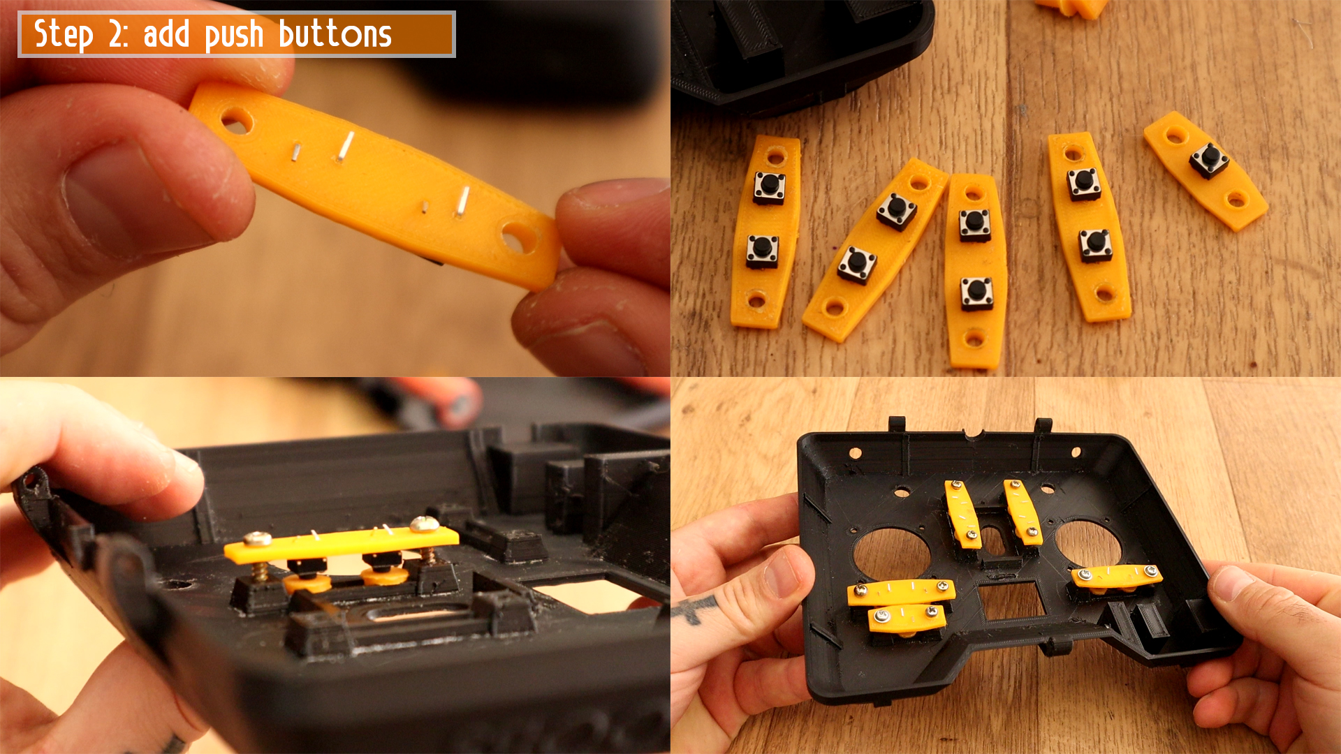
Step 2 is to add all the small push buttons. Place 2 buttons on each support as you can see below. Also, one button on the small support. Then, add a small plastic push button in each hole on the top aprt of the case and then we screw in place all the supports on the top part of the 3D printed case.
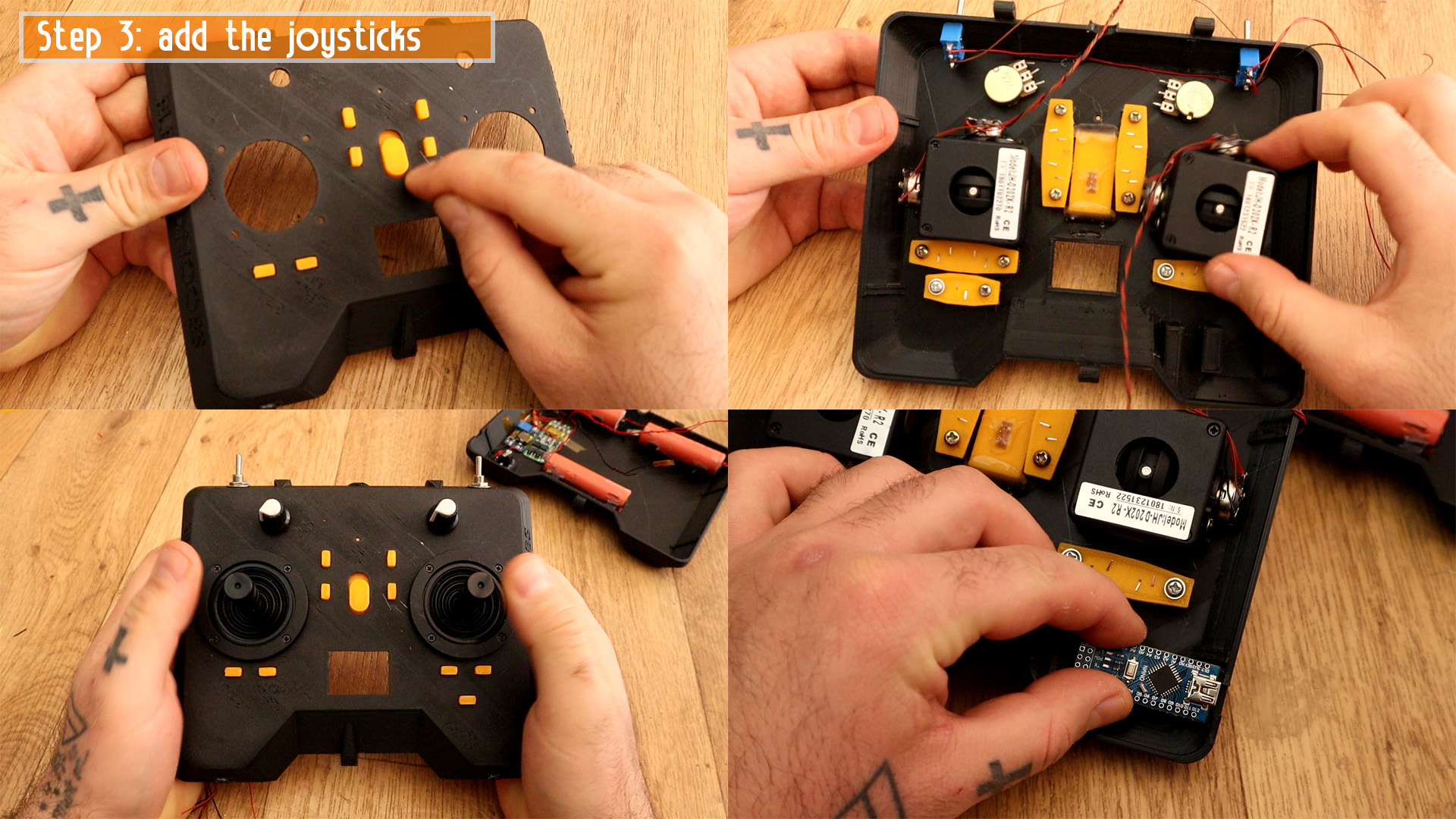
Now, add wires to the potentiometers of the joysticks for GND, 5V and signal. Then screw in place the joysticks and also the sliding switch in the middle of the controller. Add the toggle switchs and the potentiometers on the top side. Finally, glue in place the Arduino NANO on one corner.
Ok, now,
Ok, for the code, make sure you downlaod and install the OLED and NRF24 libraries from the link below as well. Then, download the code, compile and uplaod it to the Arduino. For more details read the comments in the code in order to know how to tune all the values for the joystick read and the battery read as well.
#include <SPI.h>
#include <nRF24L01.h>             //Downlaod it here: https://www.electronoobs.com/eng_arduino_NRF24.php
#include <RF24.h>
#include <Wire.h>
#include <Adafruit_GFX.h>         //Downlaod it here: https://www.electronoobs.com/eng_arduino_Adafruit_GFX.php
#include <Adafruit_SSD1306.h>     //Downlaod it here: https://www.electronoobs.com/eng_arduino_Adafruit_SSD1306.php
#include <EEPROM.h>