Panel Cookies
SteamPunk Radio
Help me by sharing this post

PREVIOUS POST       NEXT POST

Author Andrei
02/09/2019

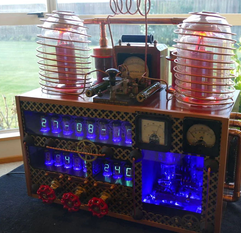
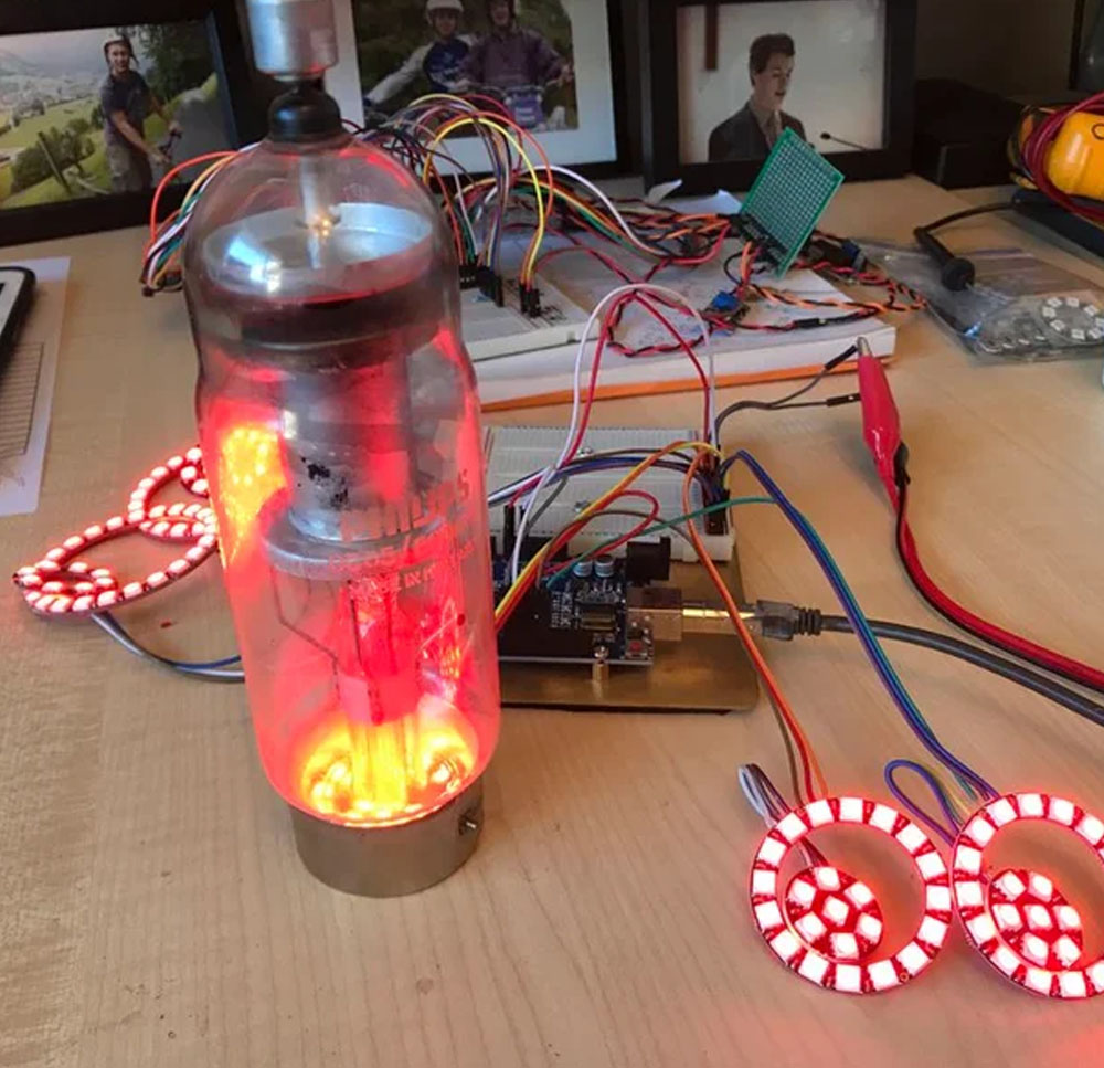
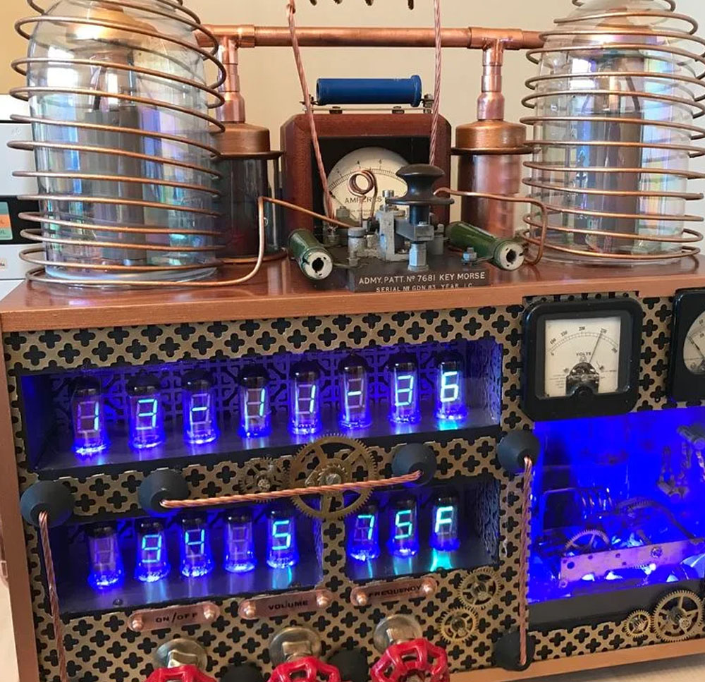
This is another very interesting project witha cool look with sixteen IV-11 VFD tubes, two Arduino Mega cards, ten LED Neon light circuits, a servo, an electromagnet, two MAX6921AWI IC Chips, five DC power supplies, a HV power supply, two DC Volt meters, a DC Amp meter, FM stereo radio, 3W power amplifier, LCD screen, and keyboard. Apart from this list, two software programs had to developed from scratch and finally the construction of the entire radio required about 200 hours of work and was made by ChristineNZ.
He decided to include this project onto the Instructables site not expecting members to reproduce this project in its entirety but rather to cherry pick the elements that where of interest to them.


This projects’ use of the MAX6921AWI chip builds on of his previous Alarm Clock project. Each set of eight IV-11 tubes are controlled via a single MAX6921AWI chip using the Multiplex method of control. The two attached PDFs show the wiring of the eight-tube set and how the MAX6921AWI chip is wired to the tube set and, in its turn, wired to the Arduino Mega 2560. Strict colour coding of the wiring is required to ensure that segment and Grid voltage lines are kept separate. It is very important to identify the tube outputs, see attached PDF on full post, this includes the 1.5V heater pins 1 and 11, the 24v anode pin, and finally the eight segment and “dp” pins, 3 – 10. At this time, it is also worth testing each segment and “dp” using a simple test rig before starting to wire the tube set. Each tube pin is wired in series with the next down the line of tubes till the last tube where extra wiring is added to allow remote connection to the MAX6921AWI chip.


As the project name suggests this is a radio and he decided to use a RDA5807M FM module. While this unit was work well its format requires very great care in attaching wires in order to create a PCB board. The solder tabs on this unit are very weak and will break off making it very difficult to solder a wire onto that connection. See full post here with more details and step by step.

Apart this post, if you have your own project and you need good quality PCBs, consider using the services of JLCPCB.com which will offer you quite good services, I use their services a lot of my PCBs.

Consider supporting ELECTRONOOBS on PATREEON.


Help me by sharing this post

PREVIOUS POST       NEXT POST


yt_link
insta_link
fb_link
twitter_link
Blog#93 - SteamPunk Radio

Last tutorials

All about Arduino PWM frequencies
Debug Arduino and ESP with PlatformIO
Homemade Best Two Hand Multimeter with Arduino
Homemade Baby White Noise Generator
Measure AC RMS with Arduino

ADVERTISERS


Affiliate Disclosure

ADVERTISERS


PCBWAY PCB service


Curso Arduino Online nivel Intermedio