Today we will take a look over what is FOC control, create an awesome PCB and control a triple phase brushless motor with it at very low speeds and precise movement. FOC is a very common and useful method of controlling brushless motors and is used a lot in robotics. I want to explain to you how it works, how the PCB is made and show you the code and an example for an open loop control and then a closed loop control using a magnetic encoder which is also very important. As always, you can get from below the PCB files, the schematic and everything you need to make the same project. So guys, let’s get started.
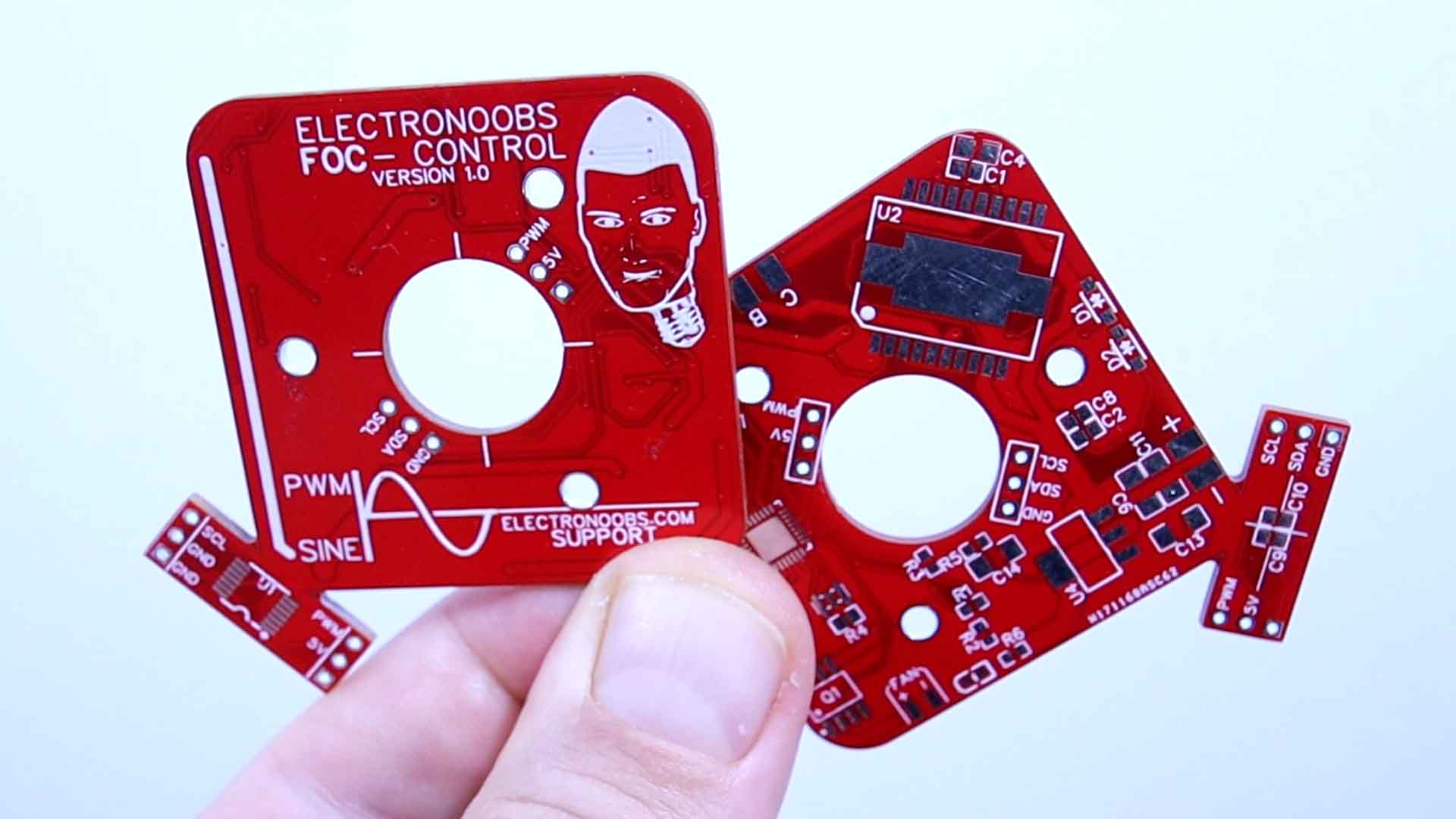
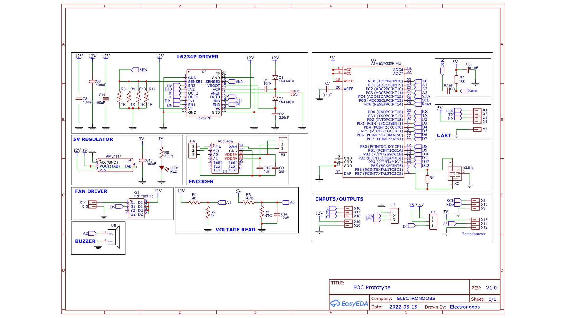
Today we don’t make a normal brushless motor controller or so-called ESC. We make a controller that is called FOC and stands for field-oriented control and for this project I’ve made a PCB that you could download from below and order it at PCBWAY as always, and make the same project. It has everything you need and it has screws for the motor, a smaller PCB for the magnetic encoder which is very important, it also has the triple phase driver and an ATMEGA328 microcontroller and a bunch of inputs and outputs. So get my files and go to PCBWAY.com and click the quote now button. Insert the PCB size and select the amount and solder mask color. Click save to cart and on the next page upload my GERBER files. Place the order in just a couple of minutes and receive perfect PCBs. They look amazing with the red solder mask. I’ve made the design in such a way that later we can cut the tiny part and place it over the big PCB.
The PCB is compatible with Arduino and you have to solder the ATmega328p chip, the 16MHz resonator, some small resistors, the 5V regulator and the motor driver. Follow the schematic and solder all the needed components. We also need big resistor for the sense pin of the driver. The PCB also has a space for a buzzer and inputs for PWM or potentiometer analog read. On the PCB we also have a MOSFET and a fan connector in case that we want to contrtol a fan and cool the driver.
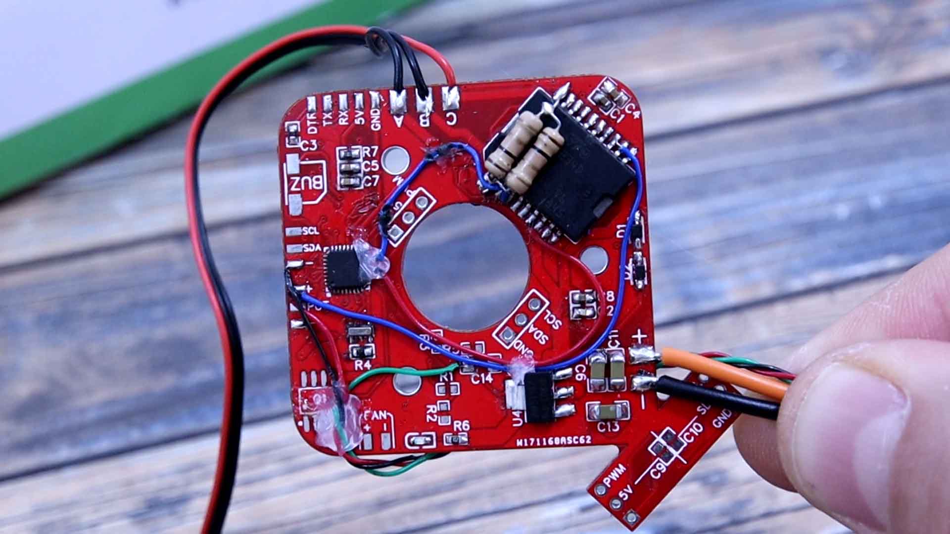
The schematic is quite easy. The basic configuration of the ATmega328 chip. Then, we connect the PWM pins to the driver and from the driver to the brushless motor pads. We create the 5V regulation from 12 to 16V main input. We also have some voltage dividers in order to read the voltage input with the Arduino ADC.
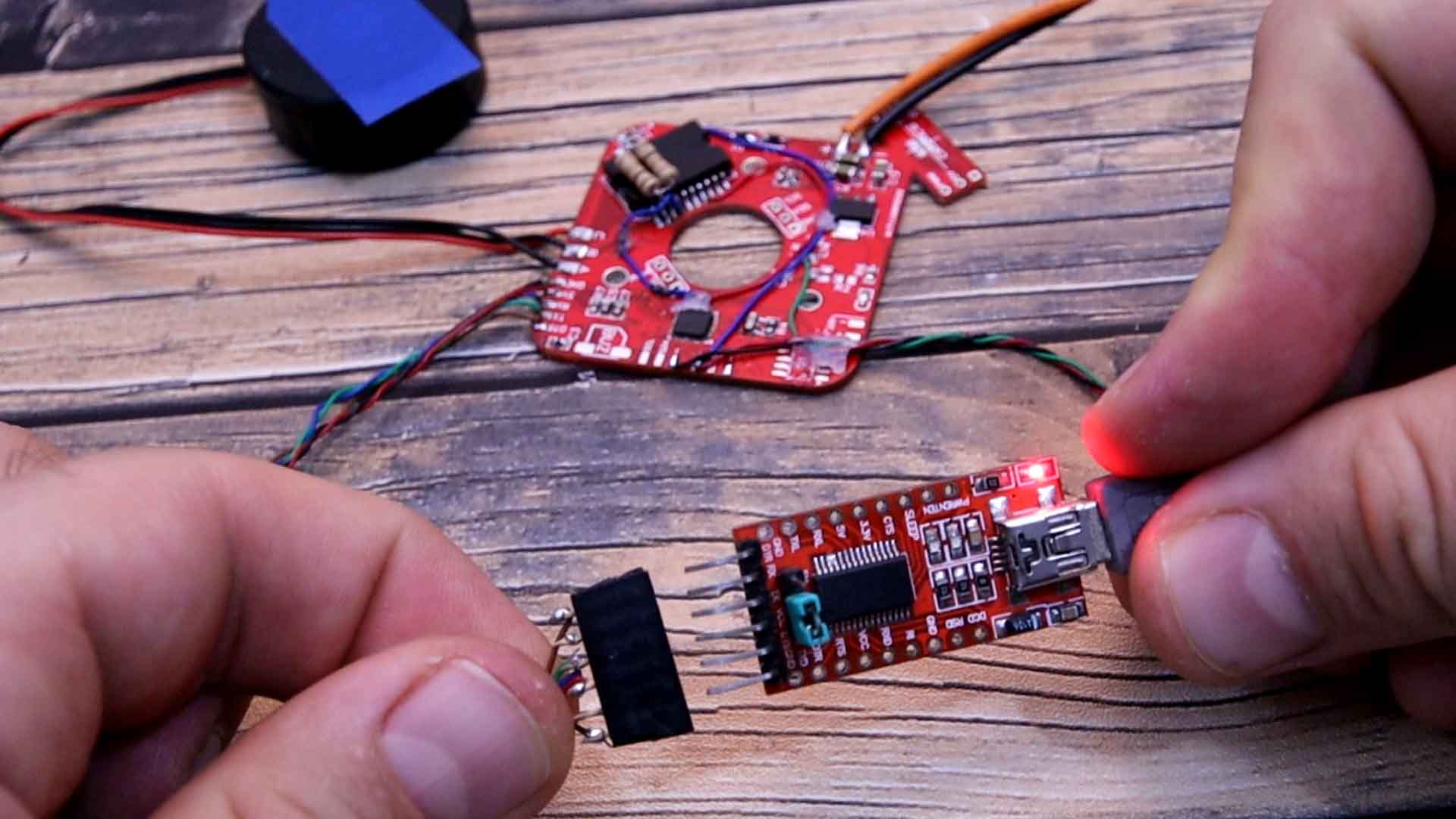
In the code we pass from angle to radians by multiplying our angle by PI and dividing it by 180, then we use the sine function to get the value and then multiply that by 127 which is the middle point of the analog write function and we sum the other half of 127 because the analog write doesn’t work with negative values. The first code we will test is for open loop control of the angle so we have no feedback and this is the code on the link below. In the setup loop we must set the frequency of pins 9, 10 and 11 to be the same, using registers. We add 120 to each phase in order to add the phase difference. To keep the values in range of 0 and 359. Then we calculate the SPWM analog values with the formula before. We write the PWM values to each pin of the motor using analog write. To control the angle, in the void loop we read the potentiometer and we multiply that value by the 360 degrees and we equal it to the phase A value. I upload this code to my PCB using an external FTDI module connected on RX, TX and DTR pins and let’s see the results.
//Inputs and outputs
const int potentiometer = A3;     // The speed/angle potentiometer is connected on this pin
const int Enable_Pin = 8;         // Enable pin for the driver
const int Motor_phase_A = 9;      //Pin for driver input of phase A
const int Motor_phase_B = 10;     //Pin for driver input of phase B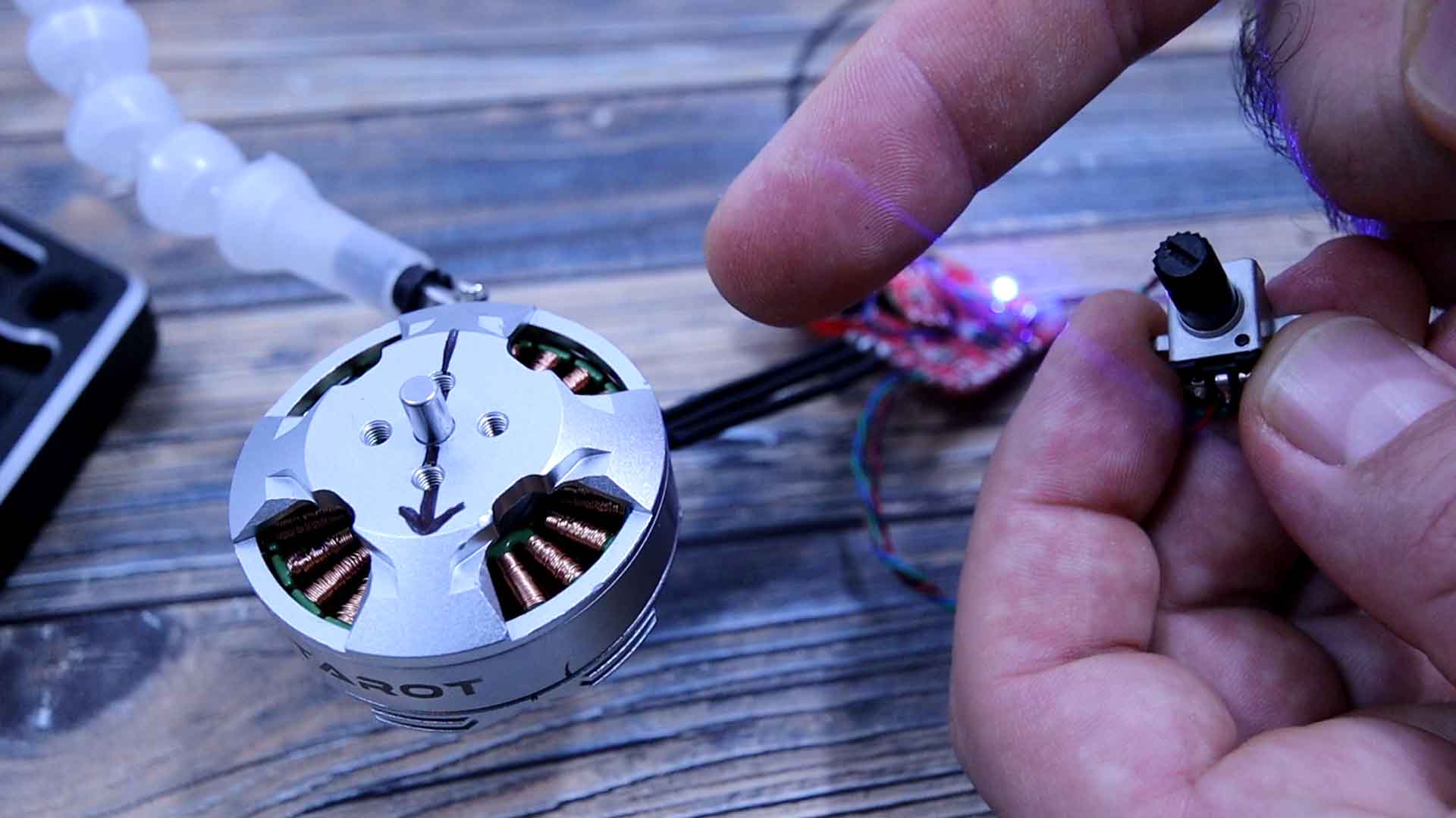
const int Motor_phase_C = 11; //Pin for driver input of phase C}The next example is using the same code but instead of changing the position, we create a continuous loop and we change the delay in between each loop by reading the potentiometer. By that we control the speed so I upload this code and as you can see, we can now control the rotation speed using the potentiometer. The motor is still in FOC control but we change the frequency. It can go very slow. It almost looks like it doesn’t move, but trust me, it moves.
You can get the files for my PCB for free, the schematic and everything you need from the links here on electronoobs.com. I hope that you like this project and that you have learned something new. If so, give me a like or comment on my YouTube channel. If my videos help you, consider supporting my work on my PATREON or a donation on my PayPal. Thanks again and see you later guys.