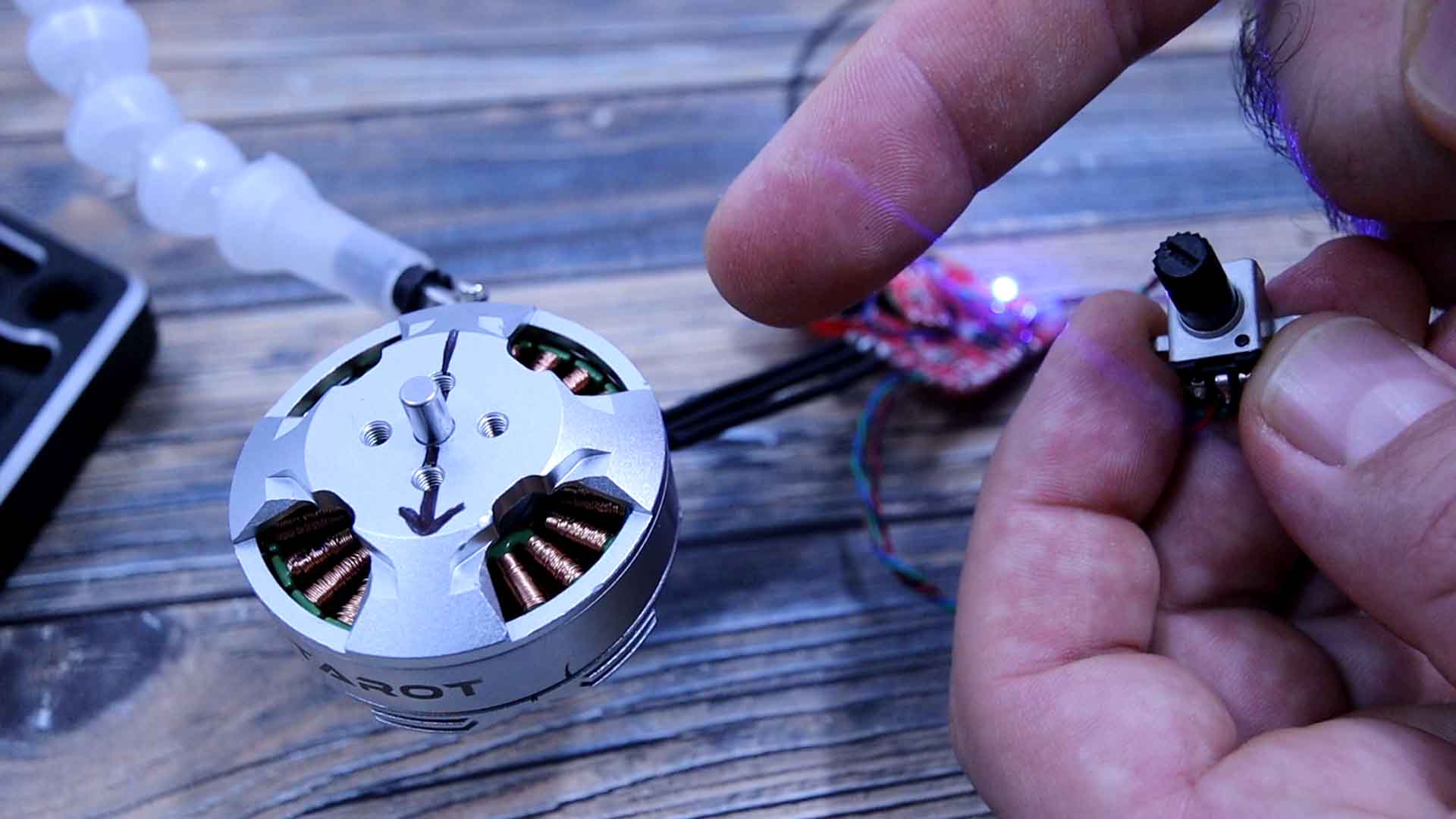
The next example is using the same code but instead of changing the position, we create a continuous loop and we change the delay in between each loop by reading the potentiometer. By that we control the speed so I upload this code and as you can see, we can now control the rotation speed using the potentiometer. The motor is still in FOC control but we change the frequency. It can go very slow. It almost looks like it doesn’t move, but trust me, it moves.
/* Open loop FOC control of the angle of a brushless motor
 * More on https://electronoobs.com/eng_arduino_tut176.php"
 * YouTube channel: https://www.youtube.com/c/ELECTRONOOBS */

//Inputs and outputs
const int potentiometer = A3;     // The speed/angle potentiometer is connected on this pin
const int Enable_Pin = 8;         // Enable pin for the driver
const int Motor_phase_A = 9;      //Pin for driver input of phase A
const int Motor_phase_B = 10;     //Pin for driver input of phase B
const int Motor_phase_C = 11;     //Pin for driver input of phase C

//Variables used in the code
int16_t SINE_A = 0;               //Initial angle value of the phase A
int16_t SINE_B = 120;             //Initial angle value of the phase B
int16_t SINE_C = 240;             //Initial angle value of the phase C
int poles = 11;                   /*Amount of poles of the motor (change this value if the motor is not
                                  getting to a full rotation. For example, my motor has 28 poles but I had
                                  to add "11" in order to make a full rotation*/
uint32_t adc_read = 0;            //Variable to store the pot ADC value.


void setup() {
  Serial.begin(9600);
  //We need to set the PWM frequency to be the same for all 3 pins D9, D10 and D11
  TCCR0B = TCCR0B & 0b11111000 | 0x03 ; // Changing would affect millis() and delay() so better to leave it default (0x03).
  TCCR1B = TCCR1B & 0b11111000 | 0x01;  // Set PWM frequency at 31250Hz for D9 and 10, (0x03 is default value, gives 490 Hz).
  TCCR2B = TCCR2B & 0b11111000 | 0x01;  // Set PWM frequency at 31250Hz for D11 D3, (0x03 is default value, gives 490 Hz).

  pinMode(potentiometer, INPUT);
  pinMode(Motor_phase_A, OUTPUT);
  pinMode(Motor_phase_B, OUTPUT);
  pinMode(Motor_phase_C, OUTPUT);
  pinMode(Enable_Pin, OUTPUT);
  digitalWrite(Enable_Pin, HIGH);
}

void loop() {
  moving(); // The motor is moving.
}


void moving()
{
  SINE_A = SINE_A + 1;      //Add 1 so the rotation will continue 1 by 1
  SINE_B = SINE_A + 120;    //We have a 120 phase difference betweeen phase A and B
  SINE_C = SINE_B + 120;    //We have a 120 phase difference betweeen phase B and C

  //Range calculation of Sine Signal
  SINE_A = SINE_A%360;    //Keep the values between 0 and 359
  SINE_B = SINE_B%360;    //Keep the values between 0 and 359
  SINE_C = SINE_C%360;    //Keep the values between 0 and 359

  //Calculate the PWM values for creating a sine signal (SPWM)
  int SINE_A_PWM = sin((double)SINE_A*PI/180)*127.5+127.5;  //Multiply by PI and divide by 180 in order to pass from degrees to radians
  int SINE_B_PWM = sin((double)SINE_B*PI/180)*127.5+127.5;  //Multiply by 127.5 and add 127.5 in order to keep the range between 0-255
  int SINE_C_PWM = sin((double)SINE_C*PI/180)*127.5+127.5;  //Sine values between -1 and 1 are placed between 0-255 for PWM.

  analogWrite(Motor_phase_A, SINE_A_PWM*0.7);               //You might change the 0.7 value for more torque...
  analogWrite(Motor_phase_B, SINE_B_PWM*0.7);               //You might change the 0.7 value for more torque...
  analogWrite(Motor_phase_C, SINE_C_PWM*0.7);               //You might change the 0.7 value for more torque...

  adc_read = analogRead(potentiometer);
  delay(adc_read/15);         //Controlling the loop delay, we control the speed of rotation
}