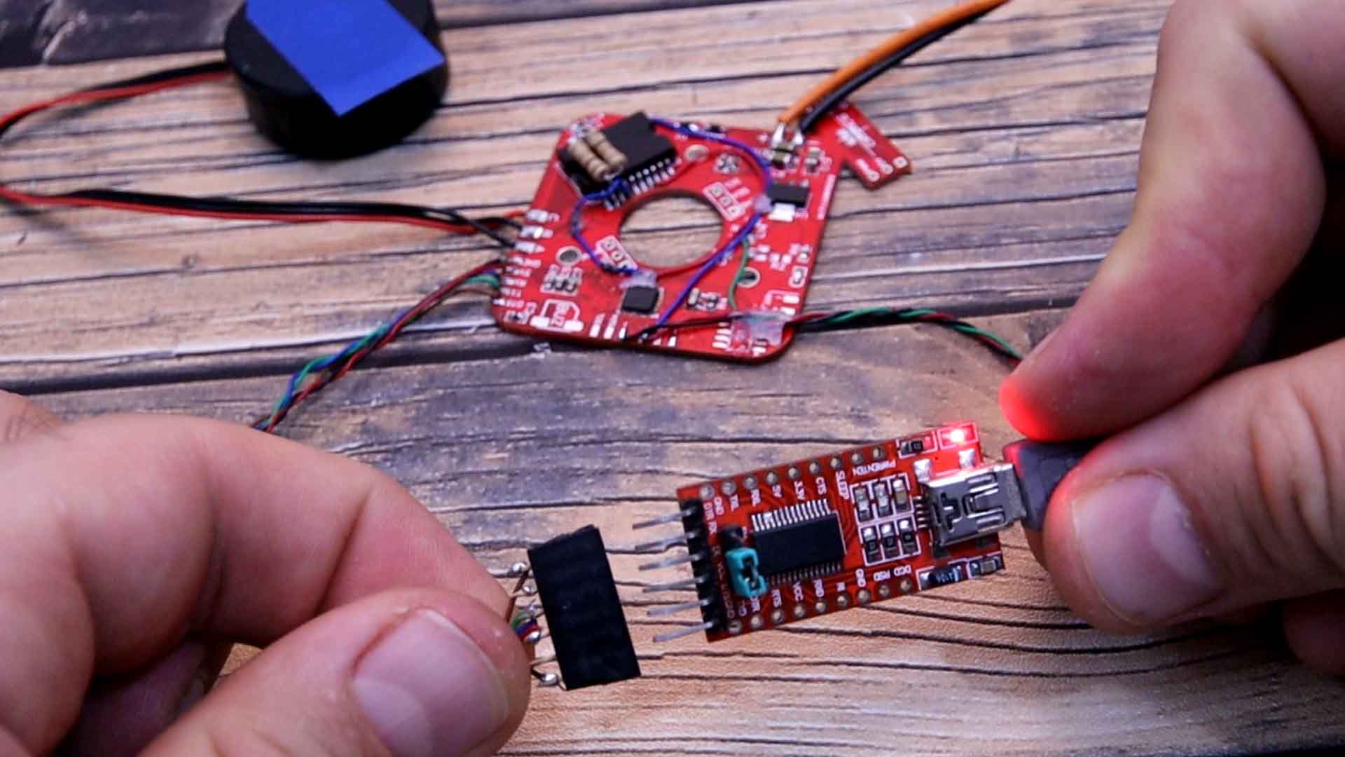
In the code we pass from angle to radians by multiplying our angle by PI and dividing it by 180, then we use the sine function to get the value and then multiply that by 127 which is the middle point of the analog write function and we sum the other half of 127 because the analog write doesn’t work with negative values. The first code we will test is for open loop control of the angle so we have no feedback and this is the code on the link below. In the setup loop we must set the frequency of pins 9, 10 and 11 to be the same, using registers. We add 120 to each phase in order to add the phase difference. To keep the values in range of 0 and 359. Then we calculate the SPWM analog values with the formula before. We write the PWM values to each pin of the motor using analog write. To control the angle, in the void loop we read the potentiometer and we multiply that value by the 360 degrees and we equal it to the phase A value. I upload this code to my PCB using an external FTDI module connected on RX, TX and DTR pins and let’s see the results.
/* Open loop FOC control of the angle of a brushless motor
 * More on https://electronoobs.com/eng_arduino_tut176.php
 * YouTube channel: https://www.youtube.com/c/ELECTRONOOBS */

//Inputs and outputs
const int potentiometer = A3;     // The speed/angle potentiometer is connected on this pin
const int Enable_Pin = 8;         // Enable pin for the driver
const int Motor_phase_A = 9;      //Pin for driver input of phase A
const int Motor_phase_B = 10;     //Pin for driver input of phase B
const int Motor_phase_C = 11;     //Pin for driver input of phase C

//Variables used in the code
int16_t SINE_A = 0;               //Initial angle value of the phase A
int16_t SINE_B = 120;             //Initial angle value of the phase B
int16_t SINE_C = 240;             //Initial angle value of the phase C
int poles = 10;                   /*Amount of poles of the motor (change this value if the motor is not
                                  getting to a full rotation. For example, my motor has 28 poles but I had
                                  to add "11" in order to make a full rotation*/
uint32_t adc_read = 0;            //Variable to store the pot ADC value.
uint16_t pot_angle;               //Variable to store setpoint angle.


void setup() {
  Serial.begin(9600);
  //We need to set the PWM frequency to be the same for all 3 pins D9, D10 and D11
  TCCR0B = TCCR0B & 0b11111000 | 0x03 ; // Changing would affect millis() and delay() so better to leave it default (0x03).
  TCCR1B = TCCR1B & 0b11111000 | 0x01;  // Set PWM frequency at 31250Hz for D9 and 10, (0x03 is default value, gives 490 Hz).
  TCCR2B = TCCR2B & 0b11111000 | 0x01;  // Set PWM frequency at 31250Hz for D11 D3, (0x03 is default value, gives 490 Hz).

  pinMode(potentiometer, INPUT);
  pinMode(Motor_phase_A, OUTPUT);
  pinMode(Motor_phase_B, OUTPUT);
  pinMode(Motor_phase_C, OUTPUT);
  pinMode(Enable_Pin, OUTPUT);
  digitalWrite(Enable_Pin, HIGH);
}


void loop() {
  moving();             // Function for moving the motor
  //Read the potentiometer 10 times for better values
  for(uint8_t i=0;i<i++){
    adc_read += analogRead(potentiometer);
    delayMicroseconds(100);
  }
  adc_read=adc_read/10;
  /*The ADC read with the arduino is from 0 to 1023. We need to pass from ADC read to angle of the motor
    For that we multiply by 360 whitch is a full sine rotation. But to make a full motor rotation, we need
    a few sine rotations, that's why we multiply by the "poles" variable */
  pot_angle = (((float)adc_read)* (360*poles)/1024);
  SINE_A = pot_angle;     //Pass the degree information to the SINE_A variable
}


void moving(){
  SINE_B = SINE_A + 120;  //We have a 120 phase difference betweeen phase A and B
  SINE_C = SINE_B + 120;  //We have a 120 phase difference betweeen phase B and C

  //Range calculation of Sine Signal
  SINE_A = SINE_A%360;    //Keep the values between 0 and 359
  SINE_B = SINE_B%360;    //Keep the values between 0 and 359
  SINE_C = SINE_C%360;    //Keep the values between 0 and 359

  //Calculate the PWM values for creating a sine signal (SPWM)
  int SINE_A_PWM = sin((double)SINE_A*PI/180)*127.5+127.5;  //Multiply by PI and divide by 180 in order to pass from degrees to radians
  int SINE_B_PWM = sin((double)SINE_B*PI/180)*127.5+127.5;  //Multiply by 127.5 and add 127.5 in order to keep the range between 0-255
  int SINE_C_PWM = sin((double)SINE_C*PI/180)*127.5+127.5;  //Sine values between -1 and 1 are placed between 0-255 for PWM.

  analogWrite(Motor_phase_A, SINE_A_PWM*0.7);               //You might change the 0.7 value for more torque...
  analogWrite(Motor_phase_B, SINE_B_PWM*0.7);               //You might change the 0.7 value for more torque...
  analogWrite(Motor_phase_C, SINE_C_PWM*0.7);               //You might change the 0.7 value for more torque...
}