This project is awesome, and I bet that you want one as well. This is yet the best multimeter I’ve made so far and let me tell you why. Well, first of all, is homemade, and that’s awesome, especially knowing that I’ve designed it myself. But second of all, it is very small but it has a lot of modes. It can measure voltage very precisely. The same for resistance and also capacitance. And if that is not enough, it can also measure inductance which usually is a bit more complicated, but this one does it very well. And on top of that we also have other modes for current measurement, frequency, continuity, pulse generator, diodes and who knows what other modes I could program for future firmware updates. And on top of that, it also has a space for a Bluetooth module so we could connect it to our smart glasses project and see the measurement in front of our eyes, that’s pretty cool, right? Is very easy to use with both hands and you don't have to place it over a table as you do with common multimeters, that’s very practical. Is rechargeable with a USB connector and it has battery protection and much more. I’m sharing all my files with you and also the code as open source in case that you want to make the same project. So let me show you all the details about this PCB, the code, how it works and make the entire multimeter. This was more than 1 year of work. So guys, let’s get started.
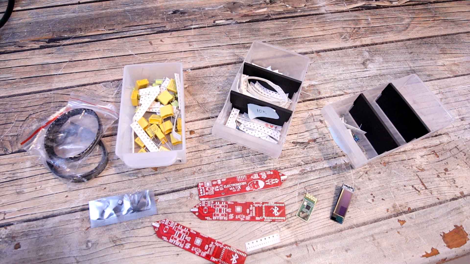
Check the scheamtic on the next part for all the values. But this is the list for the components that we need to make this PCB. Have in mind taht for example, for the ATMEGA328p-MU is better to just take it out from an Arduino NANO clone togehter with the 16MHz resonator. For the ADS1115 and the ACS712, the same, just take them out from premade modules. Sometimes, the module is cheaper than just the IC, especially these days with this IC scarcity. For the 0402 resistors and capacitors, you have the values on the schematic. For the SMD OLED display, again, just buy the module, desolder the SMD strip of the display and then solder it on the multimeter PCB (be careful of the orientation). For the HC-05 module, make sure you get the SMD vrsion and not the full module. You also have links for the 3D case and the GERBERs of the PCB for free. But you could also get it from my shop and like that you support my work. Thank you.
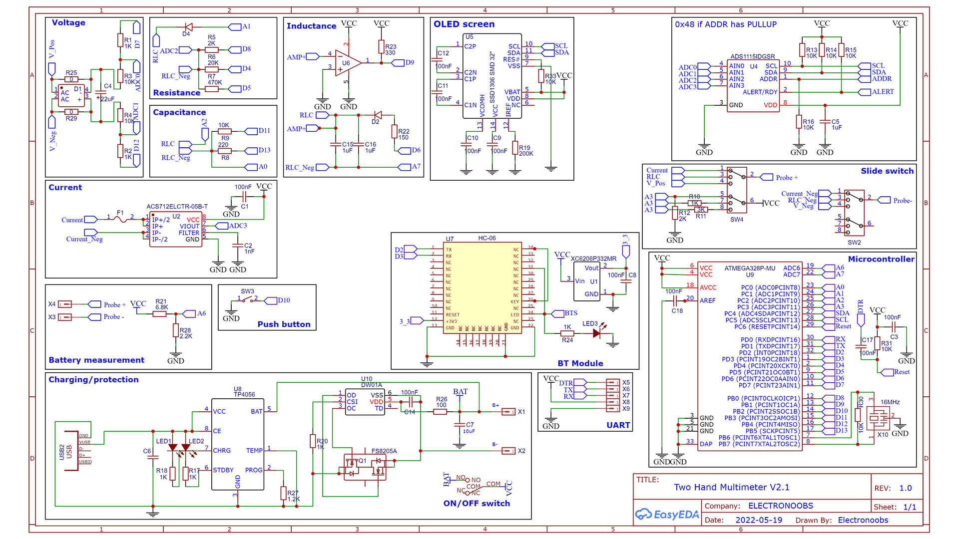
The scheamtic is complex but I've tried to separate it into individual parts for voltage measurement, resistance, current and so on. You could solder each part one by one and test them out for degug. Soldering 0402 components is not that difficult. Aslo, if you don't use the BT module, you don't have to solder it neighter the 3.3V regulator. Follow the values below.
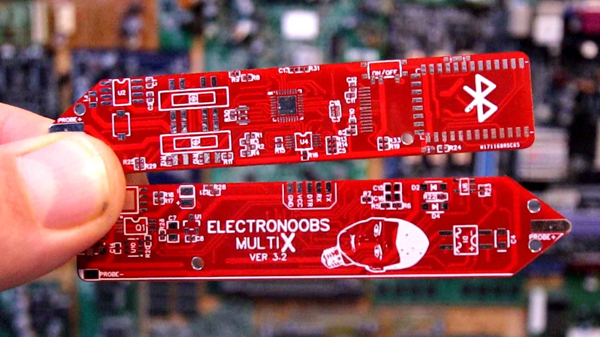
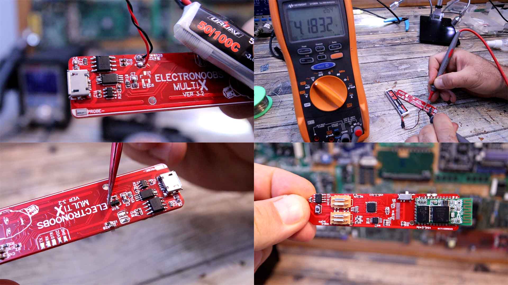
Before we go over the code and all the modes, we need to assemble it. With help from PCBWAY I was able to improve my prototype getting better and better and this is the final PCB. As you can see, it is very, very small for a multimeter, measuring only 1 and a half cm wide. So guys, get the GERBER files for the PCB from below and then we go to our dear PCBWAY. We click the quote now button and insert the size of the PCB. I also select the amount of the PCBs and the color of the solder mask, red in my case. Save to cart and on the next page upload the GERBER files you’ve downloaded from my website in a zip format. make the payment and in under 5 minutes, the order process is done. The PCBs arrive to Spain in around 10 days and they look awesome, just as I wanted them to be. Ok, now we have the PCB and is time to assemble all the components. I’ve used a lot of 0402 components which are quite small and might be a bit difficult to solder, but with patience, everything can be done. You have the full part list and the values on the schematic above, so check it out and buy each separate component. You could download it for free, or, if you want to support my work, get them from my shop for a ver small donation :)
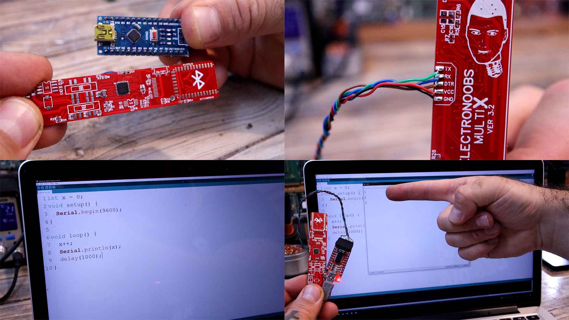
The most crucial part is the microcontroller, once it works, we can solder the rest. To make this faster, I’ve took mine out from an Arduino NANO clone, together with the 16MHz resonator. That speeds up the process and also assures you that the chip has a bootloader. When you buy a new chip, they sometimes come brand new, without a bootloader. Use the hot air gun and take out the chip and the resonator. Take the PCB and we must solder the ATMEGA328 microcontroller, the resonator, the R30 resistor, the R31 resistor and the C17 capacitor. We must have these components in order to test the microcontroller. So place some solder paste and solder the IC. You might need to retouch some of the small pins. Then add the resistors and capacitors. Then, on the back, solder wires to the UART pins for DTR, RX and TX together with GND and VCC. Connect an external FTDI module. To test the microcontroller I always upload a code like the one below. In this way, we make communication with the monitor and print a counter. Upload it and open the monitor. If you get the counter from the board, that means that the microcontroller works ok. We can now solder the rest.
Let’s solder the battery charging and protection components on the back. Also solder the USB connector. Now get a 3.7V battery and connect it to the battery pads plus and minus. Check the voltage with the multimeter and make sure everything is ok. Then connect the USB connector and check if the charging process works. If yes, we can continue. On the front part of the PCB, solder all the small resistors, the capacitors, the on and off switch, the ADC chip of 16 bits and the OPAMP. We also have some small LEDs. Soldering 0402 components is not that difficult. Carefully solder all the small components. Then I also add a small push button.
Finally we have to add two slide switches. The reason I’ve used two switches, is because I wasn't able to find a sliding switch with 3 outputs and 3 lines. We must have that in order to separate the current mode from voltage mode.
In the previous version I was using a rotary switch to do that. But that component is very very big for such a small multimeter, so I had to make this approach. Later, together with a suposables 3D printed case, we will merge these sliding switches together and they will move at the same time. Ok, solder the rest of the components on the back. And finally, we can also solder the Bluetooth module. Make sure that you solder a 3.3V regulator for the module, because more than that might burn it. Check this schematic above for all the values and components.
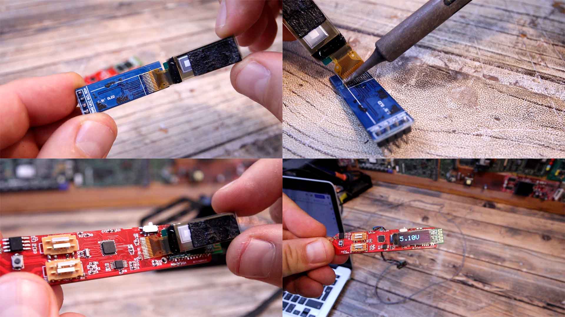
So, the PCB is ready, all that is left is to add the OLED display. For that, you can get an OLED display module and just desolder the display from the small PCB. Then solder that display on our PCB and is ready to go because it already has the needed components on the PCB. At this point you need to test each part separately.
//How to invert 180º SSD1306 display:      https://github.com/greiman/SSD1306Ascii/issues/23
#include <SPI.h>
#include <Adafruit_GFX.h>                 //download here: https://www.electronoobs.com/eng_arduino_Adafruit_GFX.php
#include <Adafruit_SSD1306.h>             //downlaod here: https://www.electronoobs.com/eng_arduino_Adafruit_SSD1306.php
#define OLED_RESET 2
Adafruit_SSD1306 display(OLED_RESET);

void setup() {
  display.begin(SSD1306_SWITCHCAPVCC, 0x3C);  // initialize with the I2C addr 0x3C (for the 128x32 or 64 from eBay)
  delay(100);
  display.clearDisplay();             //Clean the buffer
  display.display();                  //Send data to screen
  delay(100);
}

void loop() {
  int x = random(1,4);
  display.clearDisplay();             //Clean the buffer
  display.setCursor(0,0);             //Start on position 0:0
  display.setTextSize(1);             //Font size of 1
  display.setTextColor(WHITE);        //White on black
  display.print("       VOLTAGE");    //Print text with line jump
  display.setCursor(5,16);            //Move 16 pixels downwards and 5 to the right
  display.setTextSize(2);             //Now set the font to size 2
  display.print("3.");                //Print another line
  display.print(x);                   //Print "X" value which is random between 1 and 4
  display.print("V");                 //Print the "V" for volts
  display.display();                  //Finally display the created image
  delay(100);                         //Small delay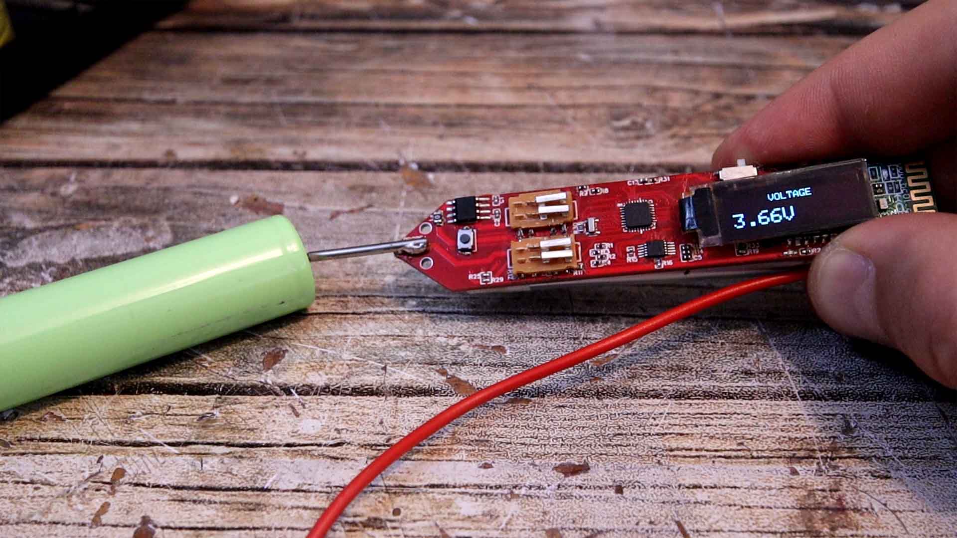
}For the probes you will need a cable and two metal pins. I’ll get mine from a cheap multimeter that cost me only 2 dollars. I solder the metal pin on the tip of the multimeter. Then I solder the red wire with the probe on the probe pin on the other side of the PCB. Now we can measure with it, so download from below the final code. Now remove the UART wires. Then we can solder the battery to the battery pads on the back. Slide the on off switch and turn it on. Slide the switch to the right and we are into voltage mode. Since the input for voltage has a voltage divider with a value of 11, this multimeter can measure up to 55V DC. The AC voltage measurement is not ready yet, since the rectifier I’ve used has a voltage drop that is too big and is not even linear…
The 3D case is not quite ready, but I will have a beter version as soon and I will also fix the rest of the problems, but I think this could be a very useful product, right? Is small, decent precision for homemade projects, is portable and rechargeable, it has multiple modes and could still have improvements. I think that the size is the best improvement from my previous PCB, right? If my videos help you, consider supporting my work on my PATREON or a donation on my PayPal. Thanks again and see you later guys.