About me
  History
  Let's learn
  Contact us
  Arduino tutorials
 Circuits tutorials
  Robotics tutorials
 Q&A
Q&A Blog
Blog  Arduino
  Circuits
 Robotics
  Modules
  Gadgets
  Printers
  Materials
  3D objects
  3D edit
  Donate
  Reviews
  Advertising


Transmitter
You can download the STL files of the Spitfire plane here. Please support me subscribing to my
This tutorial is divided in 3 parts: transmitter, body construction and the receiver.
 3D printed body
 Transmitter
 Receiver
3D printed Spitfire - Transmitter
We want to build the radio controller for our Spitfire airplane. For that we will use an old controller. I bought mine from a second hand store. All we need from the old controller is the case, joysticks and the back battery pack. We will connect an Arduino nano to the 4 potentiometers of the two joysticks. Using a power amplified NRF24 radio module we will sent the analog input values of those potentiometers to the plane receiver which will also have an NRF24 module and arduino.
1.
2.
3.
4.
5.
6.
Ok, so first we open our old radio controller case. We will se the main PCB with the joysticks. We won't need those circuits so the first thing we have to do is cut the PCB tracks using a cutter. We do that because we want to use the joysticks but we don't want to have any short circuits.
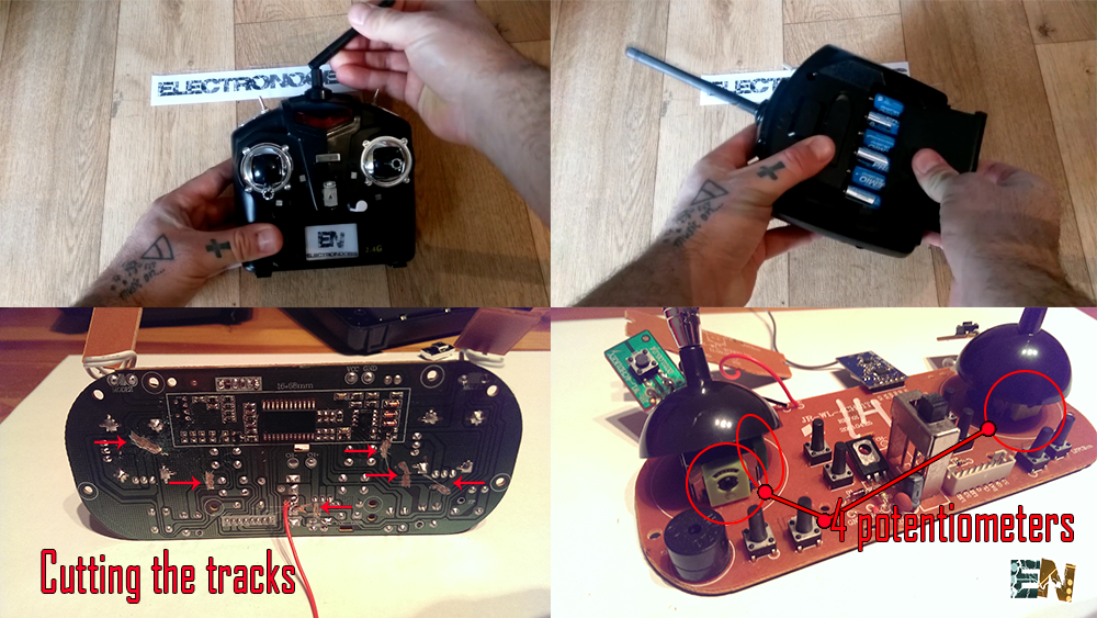
As we can see in the photo above we have to cut the tracks from each potentiometer and the main switch. We will use that switch too to power on/off the controller. The controller has a 6 1.5V battery pack with a total of 9 volts. First we have to connect the positive 9 volts to the main switch and ground to the ground of our circuit. In the next foto we can see all the connections that we have to make.
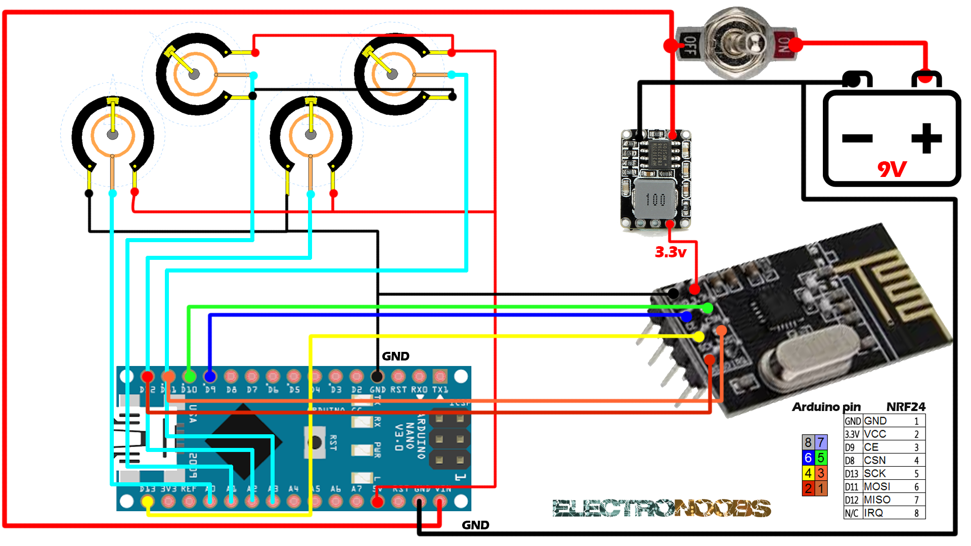
As we said before first solder the 9 volts positive output to the switch and ground to the arduino and 3.3V voltage regulator ground. Next solder a wire from the switch to the external input for the arduino and to the 3.3V voltage regulator. In this way when we switch on the switch the entire circuit is powered. We use an external voltage regulator of 3.3V because the NER24 module requires a lot of current and arduino can't supply that amount.
Finnaly connect ground and 5 volts from the arduino to each of the 4 potentiometers. Connect the output of each one to analog input A0, A1, A2 and A3 of the arduino. Our circuit is ready.
You can download the
![]()
To install it we just go to Sketch -> Include library and we open the .zip file that we've just downloaded.
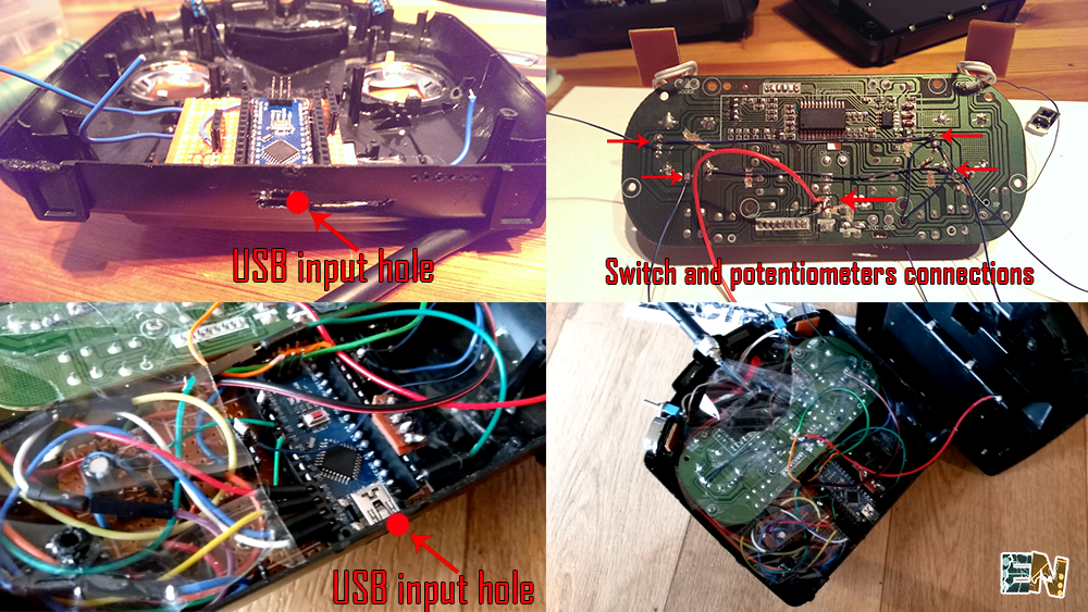
Ok, so we fit everything in the case. In my controller project I've added 2 switches and an extra potentiometer to make mine a 7 channels controller. If you whant to do that just add them, connect 5 volts and ground to them and connect the output to one of the arduino pins. late in the code you could add extra channels. I've made a hole in the case in order to program it without opening it. I glue the NRF24+PA antenna and close the case. Now it's time to program the arduino. In this example we will send 4 chanels representing the 4 analog values from the 4 potentiometers.
You can download the
To install it we just go to Sketch -> Include library and we open the .zip file that we've just downloaded.
/*A basic 4 channel transmitter using the nRF24L01 module.*/
/* Like, share and subscribe, ELECTRONOOBS */
/* http://www.youtube/c/electronoobs */

/* First we include the libraries. Download it from
   my webpage if you donw have the NRF24 library */

#include <SPI.h>
#include <nRF24L01.h>
#include <RF24.h>

/*Create a unique pipe out. The receiver has to
  wear the same unique code*/

const uint64_t pipeOut = 0xE8E8F0F0E1LL;

RF24 radio(9, 10); // select  CSN  pin

// The sizeof this struct should not exceed 32 bytes
// This gives us up to 32 8 bits channals
struct MyData {
  byte throttle;
  byte yaw;
  byte pitch;
  byte roll;
};

MyData data;

void resetData()
{
  //This are the start values of each channal
  // Throttle is 0 in order to stop the motor

  data.throttle = 0;
  data.yaw = 127;
  data.pitch = 127;
  data.roll = 127;
}

void setup()
{
  //Start everything up
  radio.begin();
  radio.setAutoAck(false);
  radio.setDataRate(RF24_250KBPS);
  radio.openWritingPipe(pipeOut);
  resetData();
}

/**************************************************/

// Returns a corrected value for a joystick position that takes into account
// the values of the outer extents and the middle of the joystick range.
int mapJoystickValues(int val, int lower, int middle, int upper, bool reverse)
{
  val = constrain(val, lower, upper);
  if ( val < middle )
    val = map(val, lower, middle, 0, 128);
  else
    val = map(val, middle, upper, 128, 255);
  return ( reverse ? 255 - val : val );
}

void loop()
{
  // The calibration numbers used here should be measured
  // for your joysticks using the TestJoysticks sketch.
  data.throttle = mapJoystickValues( analogRead(0), 13, 524, 1015, true );
  data.yaw      = mapJoystickValues( analogRead(1),  1, 505, 1020, true );
  data.pitch    = mapJoystickValues( analogRead(2), 12, 544, 1021, true );
  data.roll     = mapJoystickValues( analogRead(3), 34, 522, 1020, true );

  radio.write(&data, sizeof(MyData));
}
You can download the
Open it in arduinio IDE and upload it to the radio controller arduino.
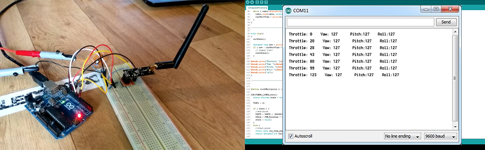
In order to test our controller we connect a NRF24 module to another arduino folowing the same connections as in the photo above. We upload the next receiver example code to it. This code should print all the received values for each channel. Once we upload the code to the receiver test arduino, open serial monitor. Power up the radio controller and see the results.
You can download the
Open it in arduinio IDE and upload it to the receiver test arduino.
In the next figure we can see the second arduino connected to another NRF24 module and with the receiver test code uploaded to it. We can see the received values printed on th serial monitor of the arduino IDE. remember to set the serail baud rate to the one in the code, if not you won't be able to see the printed values.