
 About me
  History
  Let's learn
  Contact us
  Arduino tutorials
 Circuits tutorials
  Robotics tutorials
 Q&A
Q&A Blog
Blog  Arduino
  Circuits
 Robotics
  Modules
  Gadgets
  Printers
  Materials
  3D objects
  3D edit
  Donate
  Reviews
  Advertising


BadAss Tank - Transmitter

1.
2.
3.
4.
5.
6.
7.
8.
9.
10.
11.
Intro
We will build a radio controlled Tank from scratch using Arduinos. This tutorial is divided in four parts. The construction of the radio control transmitter, the receiver, the H bridge and motor control and the tank case building. The final Tank will be 3D printed so that part of the tutorial is more for those who own a 3D printer. If you don't have a 3D printer just build a simple robot using two wheels.
BadAss Tank - Transmitter

Transmitter introduction
What we want to do is connect 4 potentiometers to the analog inputs of the arduino and send each input value to a receiver using the NRF24 module. We will create 4 radio channels, we will read each of the 4 analog inputs, map the values to the desired range and send each value using a 8 bits channel for each input.
Schematic!
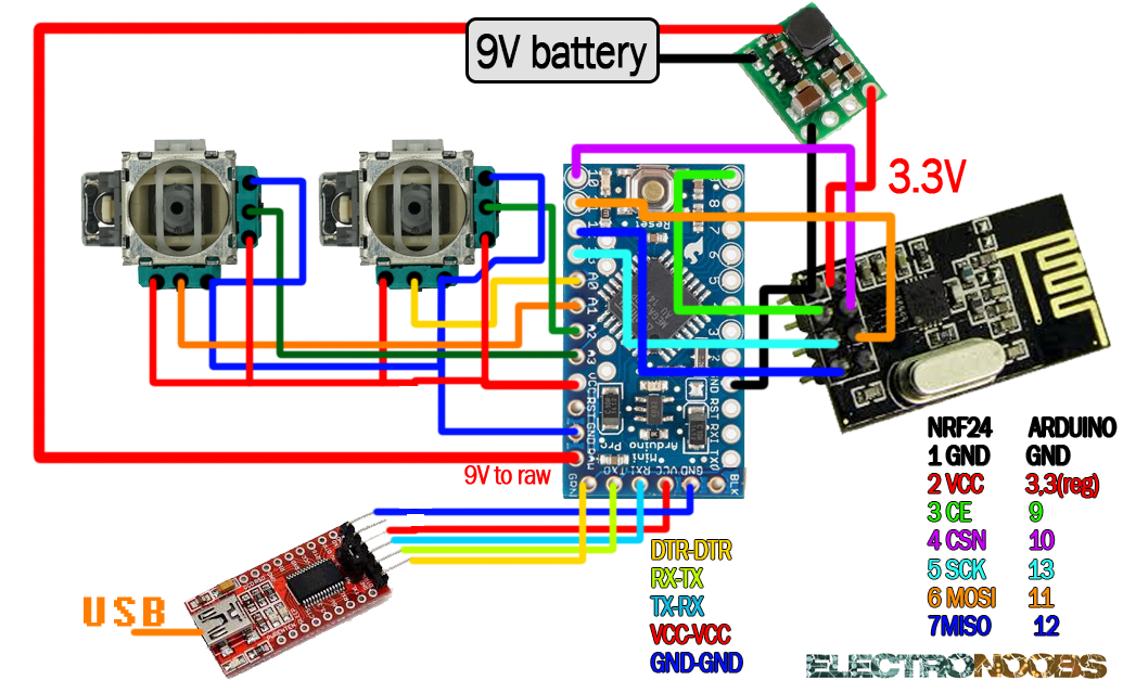
Connections!
If you are using an Arduino NANO you won't need a FTDI module to program yor microcontroller. First of all we have to power up our Arduino. To do that we connect a 9V battery directly to the RAW input pin and ground of the arduino. The launchboard must have his own 5V or 3.3V regulator. The NRF24 module use a lot of curent so we won't power it from a 3.3V output of the arduino. In stead of that we will use an external 3.3 voltage regulator. Apply a higher voltage to this module and it will burn in a second so be carefoul. We have to share ground between the NRF24 module and the Arduino. The pin conection for the radio module is shown in the picture above. All we need to do is connect the middle pin of each potentiometer to a analog input of the arduino. COnnect 5V and ground to the other 2 pins of each potentiometer and we are done.
All we need to do now is program the microcontroller and start sending data.
To install it we just go to Sketch -> Include library and we open the .zip file that we've just downloaded.
Code!
Transmitter code!
Download the
//4 channels transmitter
#include <SPI .h>
#include <nRF24L01.h>
#include <RF24.h>>
const uint64_t pipeOut = 0xE8E8F0F0E1LL; //This same code should be in the receiver as well
RF24 radio(9, 10); //select CE and CSN pins
//We can have up to 32 channels of 8 bits
struct MyData {
byte throttle; //We define each byte to an analog input
byte yaw;
byte pitch;
byte roll;
};
MyData data;
void resetData()
{//We define the start value of our data
data.throttle = 0;
data.yaw = 127;
data.pitch = 127;
data.roll = 127;
}
void setup()
{
radio.begin();
radio.setAutoAck(false);
radio.setDataRate(RF24_250KBPS);
radio.openWritingPipe(pipeOut);
resetData();
}
/**************************************************/
// We map the values from 0-1024 a 0-255,
//because we have 8 bits channels and 8 bits = 254,
//once we receive the values in the receiver we can map the values once again so don't worry
int mapJoystickValues(int val, int lower, int middle, int upper, bool reverse)
{
val = constrain(val, lower, upper);
if( val < middle )
val = map(val, lower, middle, 0, 128);
else
val = map(val, middle, upper, 128, 255);
return ( reverse ? 255 - val : val );
}
void loop()
{
// We read the analog input values
//Set to "true" it will invert the value reading
//Set to "false" it will use values from 0 to 1024
//This part is just in case you connect the pontenciometers reversing the wires
//and to adjust the values
data.throttle = mapJoystickValues( analogRead(0), 13, 524, 1015, true );
data.yaw = mapJoystickValues( analogRead(1), 1, 505, 1020, true );
data.pitch = mapJoystickValues( analogRead(2), 12, 544, 1021, true );
data.roll = mapJoystickValues( analogRead(3), 34, 522, 1020, true );
radio.write(&data, sizeof(MyData));//Sending the data
}
Now in order to test if the transmitter works well download the next code below and upload it to another arduino. Connect the NRF24 module to this second arduino in the same way as the transmitter. Power up the transmitter and open the serial monitor of the arduino IDE. This seconde test code should print on your monitor the received values. If the values are not in the range that you whant just use the "mapJoystickValues" function in the transmitter code to change the range.
You can download the