
 About me
  History
  Let's learn
  Contact us
  Arduino tutorials
 Circuits tutorials
  Robotics tutorials
 Q&A
Q&A Blog
Blog  Arduino
  Circuits
 Robotics
  Modules
  Gadgets
  Printers
  Materials
  3D objects
  3D edit
  Donate
  Reviews
  Advertising


BadAss Tank - Receiver

1.
2.
3.
4.
5.
6.
7.
8.
9.
10.
11.

Receiver
Receiver introduction
We know that our arduino radio controller from the previous part will send us 4 channels of data. Each channel with 1 byte of information, which means 0 to 254 values. We connect the NRF24 module to our arduino NANO (or MEGA if you whant) in the same way as in the transmitter part. Once we receive tne 0 to 254 values for each channel we will use those value to control the movement of our tank. Using
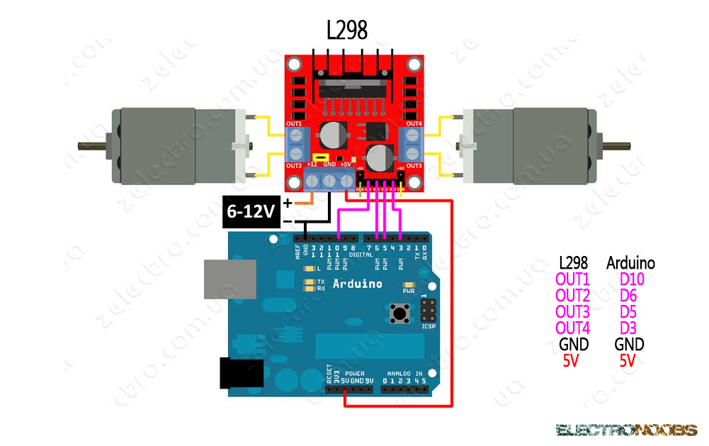
So what we need is to build or buy an H bridge module. Conect the radio module to our arduino and the arduino analog outputs to the H bridge. Connect the two DC motors to the H bridge and we are done.
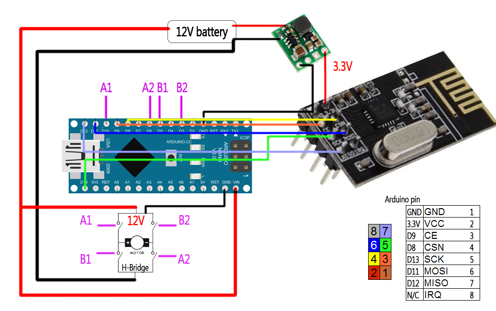
Connections!
If you are using an Arduino NANO or Mega you won't need a FTDI module to program yor microcontroller. First of all we have to power up our Arduino. To do that we connect our 12V battery directly to the RAW input pin and ground of the arduino. The launchboard must have his own 5V or 3.3V regulator. The NRF24 module use a lot of curent so we won't power it from a 3.3V output of the arduino. In stead of that we will use once again an external 3.3 voltage regulator. Apply a higher voltage to this module and it will burn in a second so be carefoul. We have to share ground between the NRF24 module and the Arduino. The pin conection for the radio module is shown in the picture above.
All is left to do now is program the microcontroller and start receiving data and controling those motors.
You can download the
To install it we just go to Sketch -> Include library and we open the .zip file that we've just downloaded.
Receiver code!
/* 4 channels receiver example (PWM output) */

#include <SPI.h>
#include <nRF24L01.h>
#include <RF24.h>
const uint64_t pipeIn = 0xE8E8F0F0E1LL; //Remember that this code is the same as in the transmitter

RF24 radio(9, 8); //Remember, here we changed the CSN pin from 10 to 8

//We could use up to 32 channels
struct MyData {
byte throttle; //We define each byte of data input, in this case just 4 channels
byte yaw;
byte pitch;
byte roll;
};

MyData data;

void resetData()
{
//We define the inicial value of each data input
//3 potenciometers will be in the middle position so 127 is the middle from 254
data.throttle = 0;
data.yaw = 127;
data.pitch = 127;
data.roll = 127;

}

/**************************************************/

void setup()
{
//We define the H bridge output pins
pinMode(10,OUTPUT);   //Left forward
pinMode(6,OUTPUT);    //Left backward
pinMode(5,OUTPUT);    //Right forward
pinMode(3,OUTPUT);    //Right bakward

resetData();
radio.begin();
radio.setAutoAck(false);
radio.setDataRate(RF24_250KBPS);

radio.openReadingPipe(1,pipeIn);
//we start the radio comunication
radio.startListening();

}

/**************************************************/

unsigned long lastRecvTime = 0;

void recvData()
{
while ( radio.available() ) {
radio.read(&data, sizeof(MyData));
lastRecvTime = millis(); //here we receive the data
}
}

/**************************************************/

void loop()
{
recvData();
unsigned long now = millis();
//Here we check if we've lost signal and if we did we reset the values unsigned long now = millis();
if ( now - lastRecvTime > 1000 ) {
// Signal lost?
resetData();
}

//we make an analogWrite using the received values
//This is just a small example, you could always start working with the values //to achive better results. We will just use one joystick (pitch and roll)

if (data.pitch > 135 && 119 < data.roll && data.roll < 135)
{
analogWrite(10,data.pitch);
analogWrite(5,data.pitch);
}

if (data.pitch < 119 && 119 < data.roll && data.roll < 135)
{
analogWrite(6,255-data.pitch);
analogWrite(3,255-data.pitch);
}

if (data.roll > 135 && 119 < data.pitch && data.pitch < 135)
{
analogWrite(10,data.roll);
analogWrite(3, data.roll);
}

if (data.roll < 119 && 119 < data.pitch && data.pitch < 135)
{
analogWrite(5,255-data.roll);
analogWrite(6,255-data.roll);
}

if (119 < data.roll && data.roll < 135 && 119 < data.pitch && data.pitch < 135)
{
analogWrite(3,0);
analogWrite(5,0);
analogWrite(6,0);
analogWrite(10,0);
}

}

/**************************************************/
Next page - 3D tank construction: