
This circuit is a so-called TRIAC dimmer or sometimes called an AC dimmer circuit. You see, a few weeks ago I made a video about universal motors and showed you how they work internally and how to connect them, but I’ve also shown you a crude circuit for controlling AC power and how to control the speed of that AC motor. That circuit is called an AC dimmer and is made with a component called a TRIAC. Today I want to explain you how AC dimming works, how a TRIAC works and why is such an important component and show you a few AC dimming circuits and test them out with motors, AC light bulbs or other AC devices. This video can be quite interesting, so guys, let’s get started.
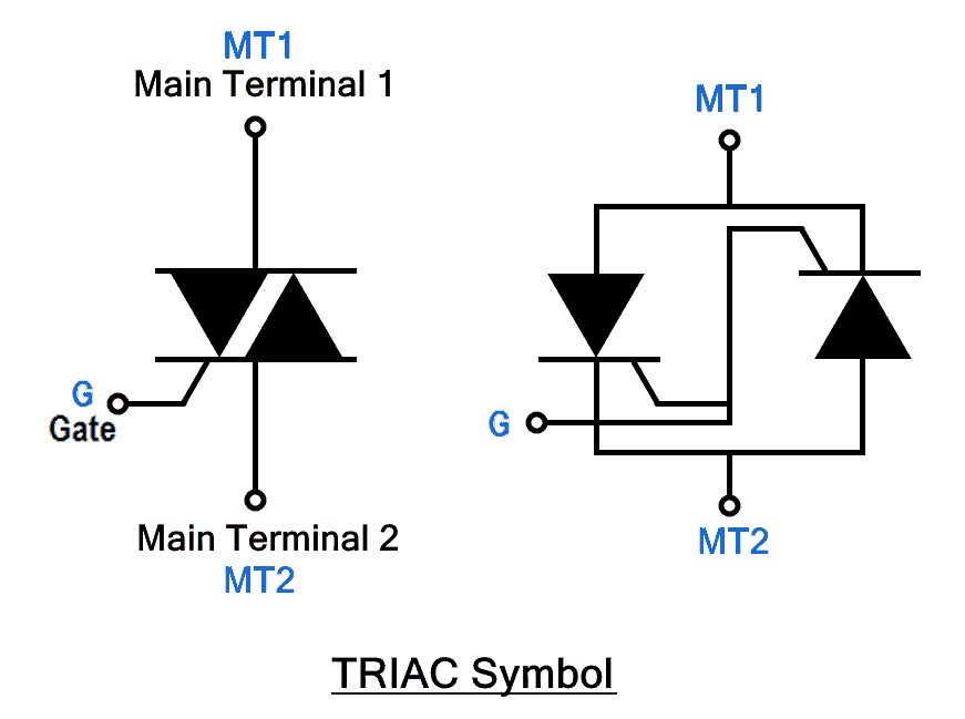
A TRIAC component is a bidirectional, three-electrode AC switch that allows electrons to flow in either direction. It is the equivalent of two SCRs connected in a reverse-parallel arrangement with gates connected to each other. A TRIAC is triggered into conduction in both directions by a gate signal like that of an SCR. TRIACs were designed to provide a means for the development of improved AC power controls. TRIACs are available in a variety of packaging arrangements. They can handle a wide range of current and voltage. TRIACs generally have relatively low-current capabilities compared to SCRs — they are usually limited to less than 50 A and cannot replace SCRs in high-current applications. TRIACs are considered versatile because of their ability to operate with positive or negative voltages across their terminals. Since SCRs have a disadvantage of conducting current in only one direction, controlling low power in an AC circuit is better served with the use of a TRIAC.
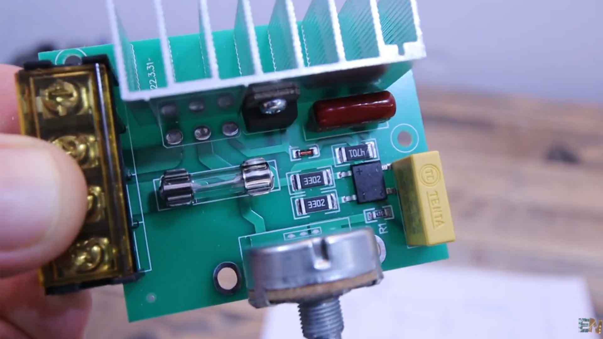
We’ve seen more about this topic in the Bluetooth TRIAC controller where we read the zero cross with the Arduino and create a firing pulse at the TRIAC gate to control the power using Bluetooth data from a smartphone. But this time, this circuit is fully analog. It has no microcontroller or digital component, only passive components. Let’s start with a very easy circuit, which is this one below. We have the TRIAC, another component called DIAC and some resistors and capacitors. To change the firing pulse time we use potentiometer and that’s how we can change the output power. This module here is using this exact circuit. But if we have no microcontroller, what is applying the pulses at the TRIAC gate with this simple circuit? Well, let’s analyze it.
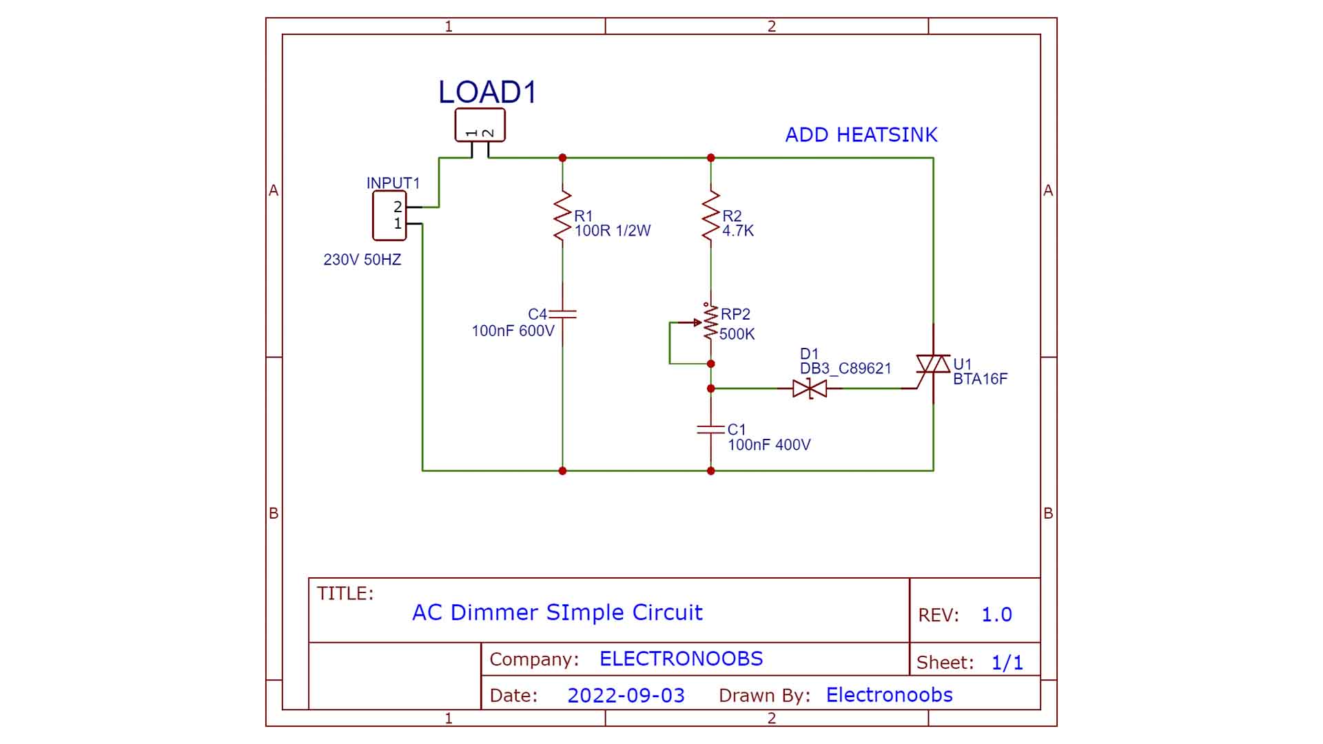
The DIAC component also allows current flow in both directions but only when a certain threshold voltage is reached. So we start with everything powered off and we apply the AC voltage at the input. Since the TRIAC is off, the output is still 0. But we have a small current flow through the R2 resistor and the potentiometer and that will charge up the capacitor C1. When the voltage value of the capacitor reaches the threshold value of the DIAC, this will allow current to flow towards the gate of the TRIAC and that’s what activates it. So now the TRIAC could allow current flow so the output is ON till the AC voltage changes polarity and the TRIAC gets OFF again. But now that small capacitor is charging with a negative polarity because the AC voltage is now on the negative side. Again, when the capacitor reaches a certain threshold value (but inverted), the DIAC will allow current flow once again and activate the gate of the TRIAC again. So as you can see, just by charging up the small capacitor we can create those firing pulses at the TRIAC gate. The capacitor charging speed is affected by the resistor and potentiometer values. The higher the resistor value, the slower the charging process will be, so the firing pulse is applied later, so the output power will be lower. That’s why we use a potentiometer, so we could regulate this resistance value making the charging process faster or slower and with that, changing the firing pulse position, so we change the output power. Quite easy, right?
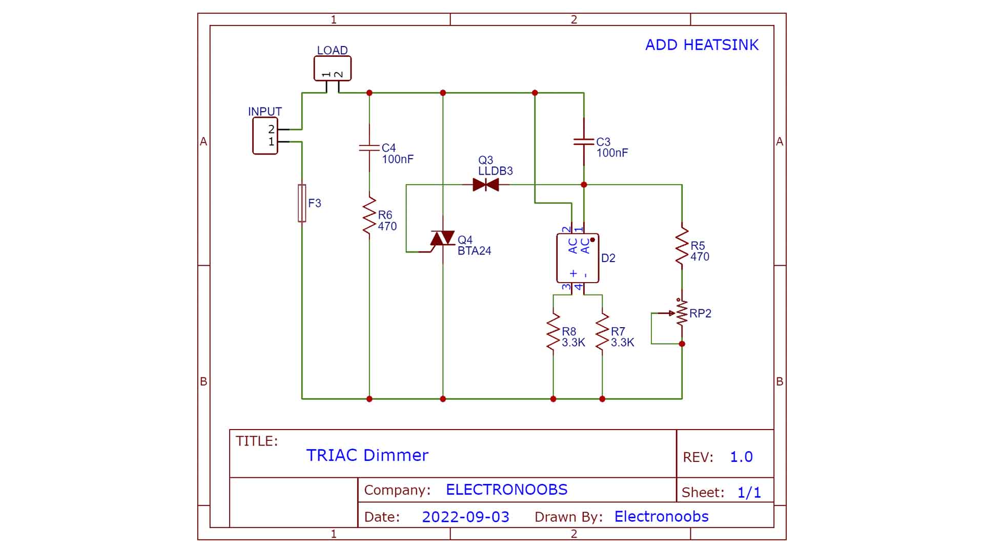
I have another model which works kind of the same but it also uses a small full bridge rectifier. I’ve managed to reverse engineer the PCB and this below is the schematic. Kind of the same, right?
Have in mind that for a lot of power the TRIAC will get hot due to power losses. That's why all AC dimmers have some sort of heatsink to dissipate that heat. The BTA24 for example could work with up to 800V and 25 amps and that’s a lot of power. But make sure to check the datasheet of each component before you make such a circuit. Have in mind that the value of the capacitor and the value of the potentiometer will change the firing time. The bigger the capacitor, the slower the charging process will be. And the same for the resistor. Usually, we also add a fuse in order to control the maximum power. This circuit for example, has a 20 amps fuse as well. Also, as you can see on the PCB of the module, the used resistors are SMD but they are very big, is a 25 12 package so they could withstand more power. The used capacitor must be rated for high voltage and also to be non polarized because we work with AC. Since we are working with high voltage that could really injure you, please be safe and if you don’t know what you're doing, is better to not try this project.
So guys, I hope you now know how a TRIAC AC dimmer works and how to control it. Check all the connections above and the full video below. If my videos help you, consider supporting my work on my PATREON or a donation on my PayPal. Thanks again and see you later guys.


