In this tutorial I'll show you how the CFL or compact fluorescent lamp works. How the tube creates light with electrodes creating electrons, mercury vapor and phosphor inside the tube. We will see the circuit for creating high voltage high frequency signal and what components it has. I hope you will learn something new.
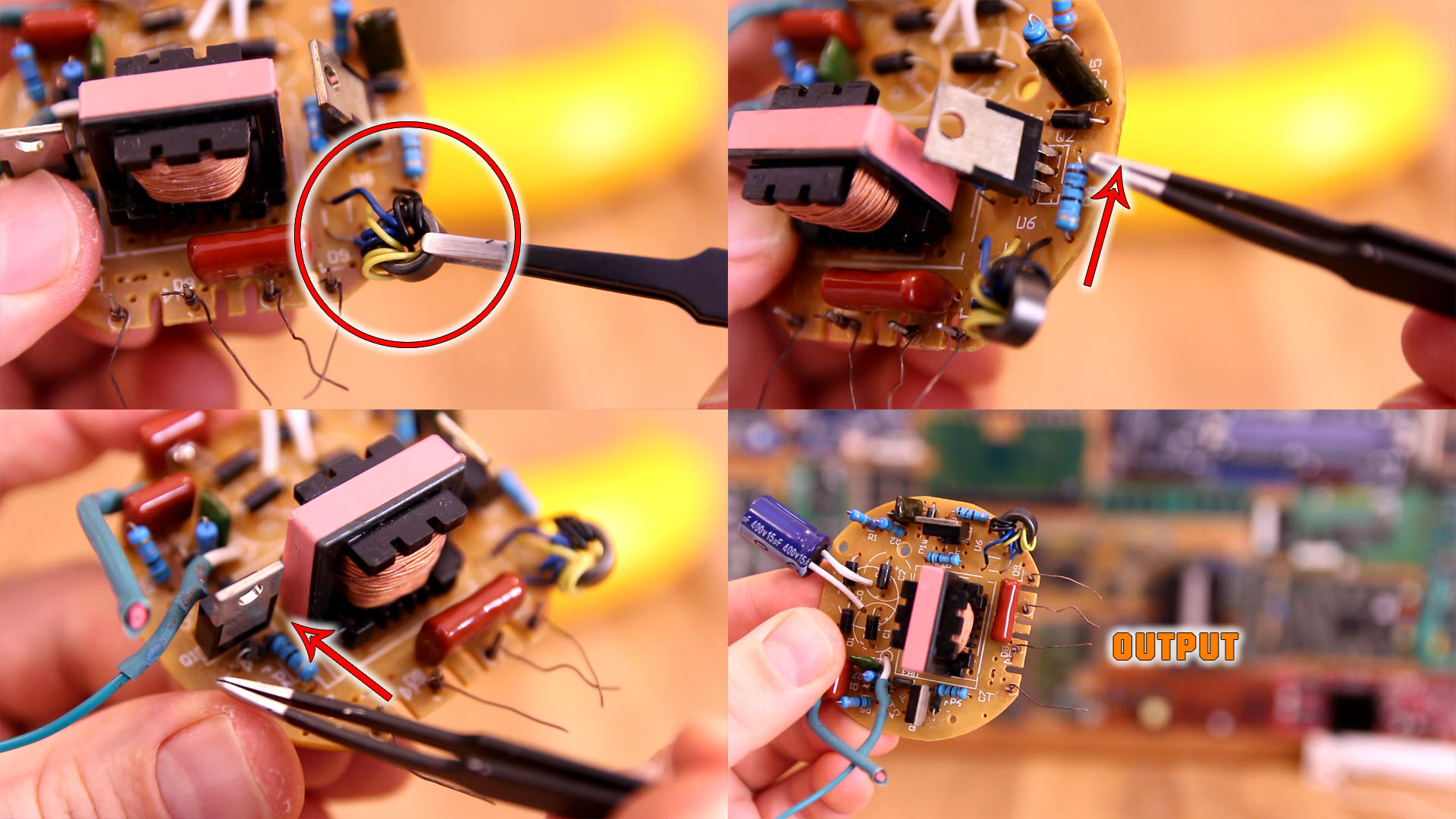
To understand the physics inside the tube, please see the PREVIOUS TUTORIAL on the fluorescent tube. Ok, not let’s study the compact electronic ballast. The PCB of a CFL ballast circuit is a combination of four different circuits. The EMI Filter Circuit, the Full-Wave Rectifier, the DC Filter Circuit and the Inverter circuit. So, instead of the ballast and the starter, how else we could get that high voltage? Well, using an electrical circuit made with transistors. As you can see on the PCB below, we have the main input connected to 4 diodes which is the full bridge rectifier.
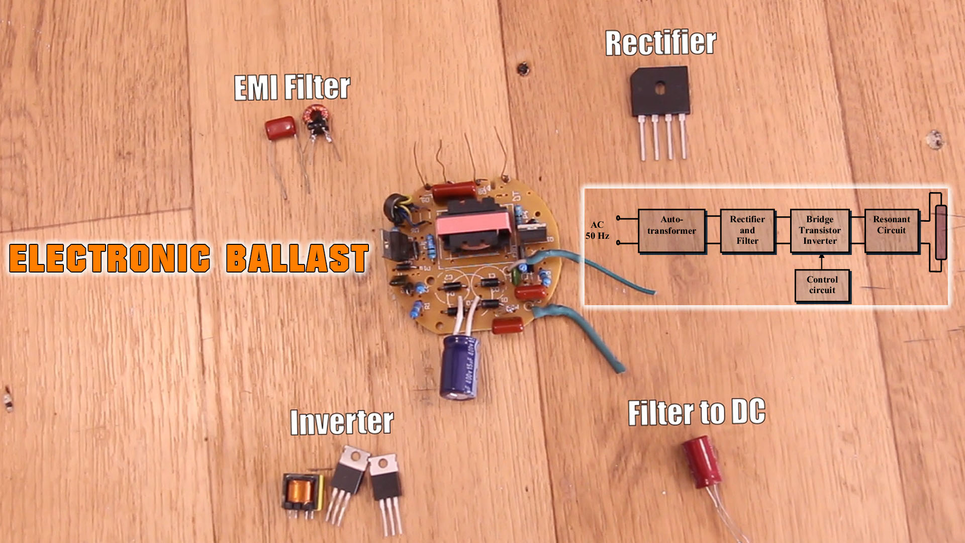
Then we have the big capacitor acting as a filter and creating steady high voltage DC. From there, we have the inverter made with two transistors. The output of the transistors is connected to a coil and another capacitor which is called a resonant tank. You see, this PCB below has not driver IC, so who will enable and disable the transistors gate? The coil and capacitor create an LC tank which will resonate and by that we create both positive and negative polarity waves.
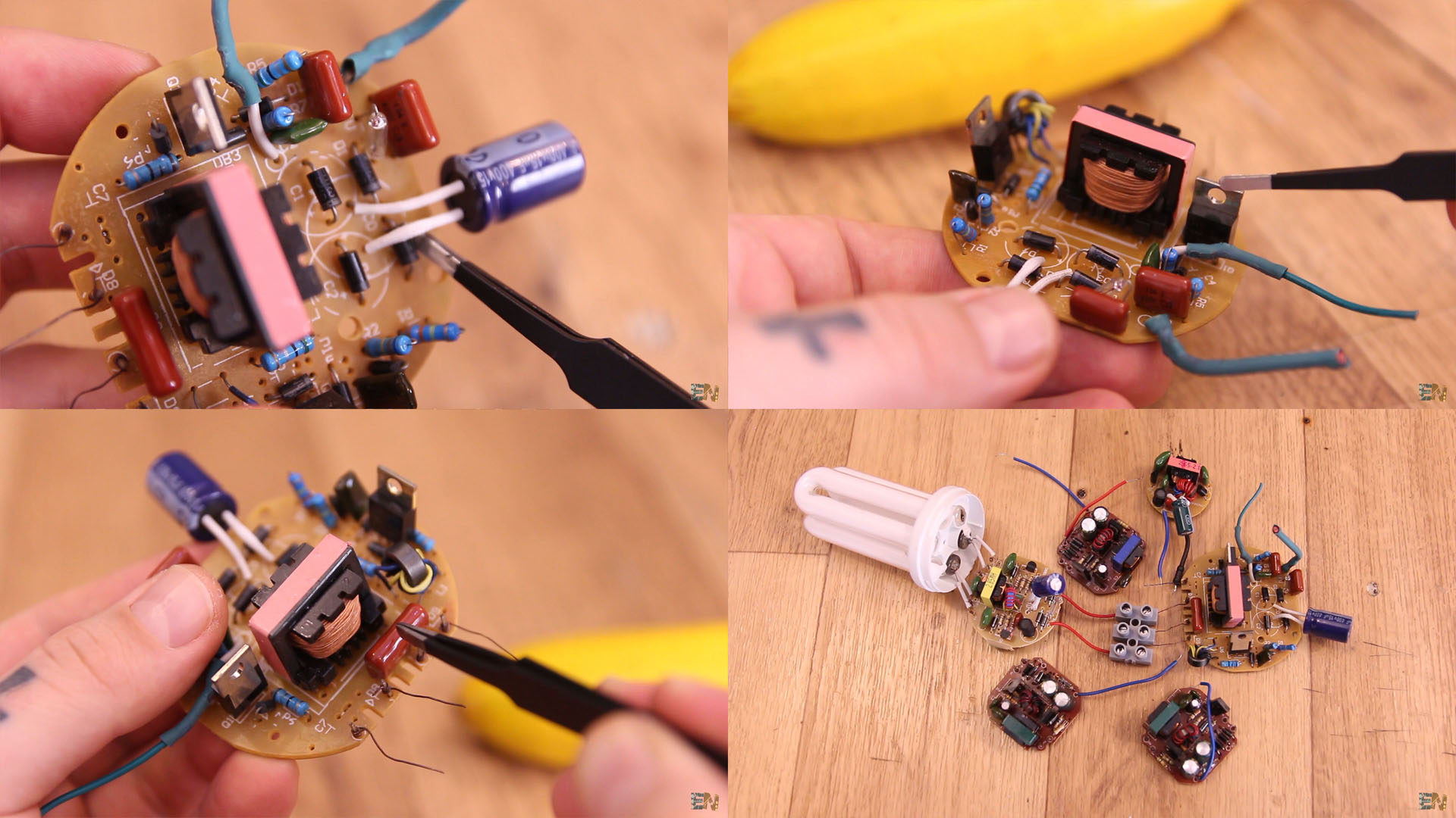
This coupled inductor below, each time the oscillation polarity changes, since it is connected to some resistors and then to the gate of the transistors, it will turn on and Off one and the other transistor. That's how we create the inverter without a driver.
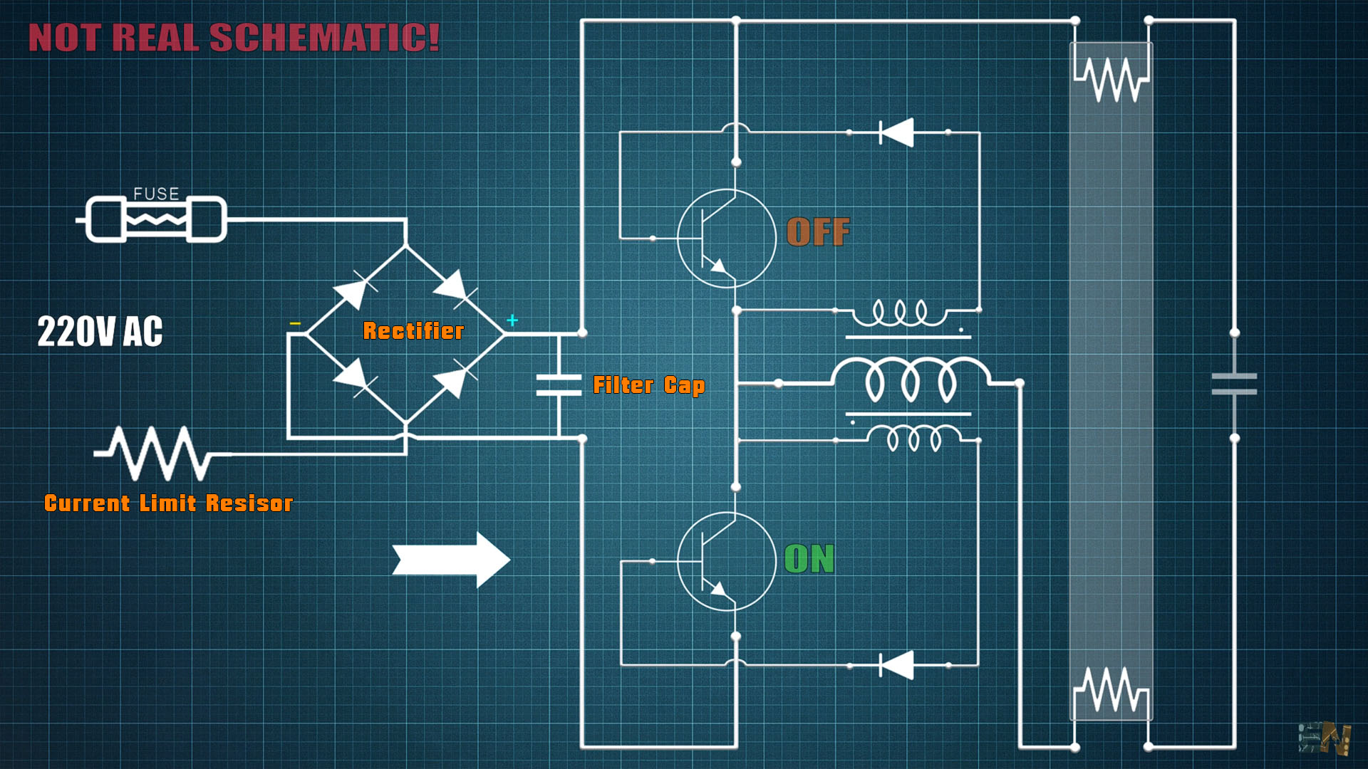
Now we add two transistors bridge. At the output of the bridge, we have our coils. In order to create the high voltage AC, we first enable the bottom transistor. So, the current will flow though the electrodes circuit from positive, though the electrodes and then though the transistors back to ground, as you can see below with the red line. That will also store energy in the coil as a magnetic field. But the coil has a capacitor on the side, the one on the other side of the tube, so this would create an LC tank.
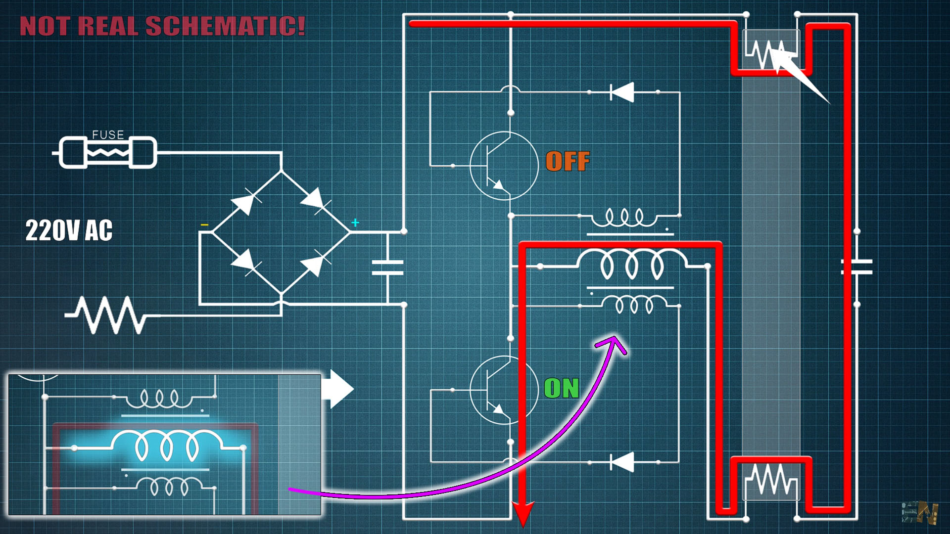
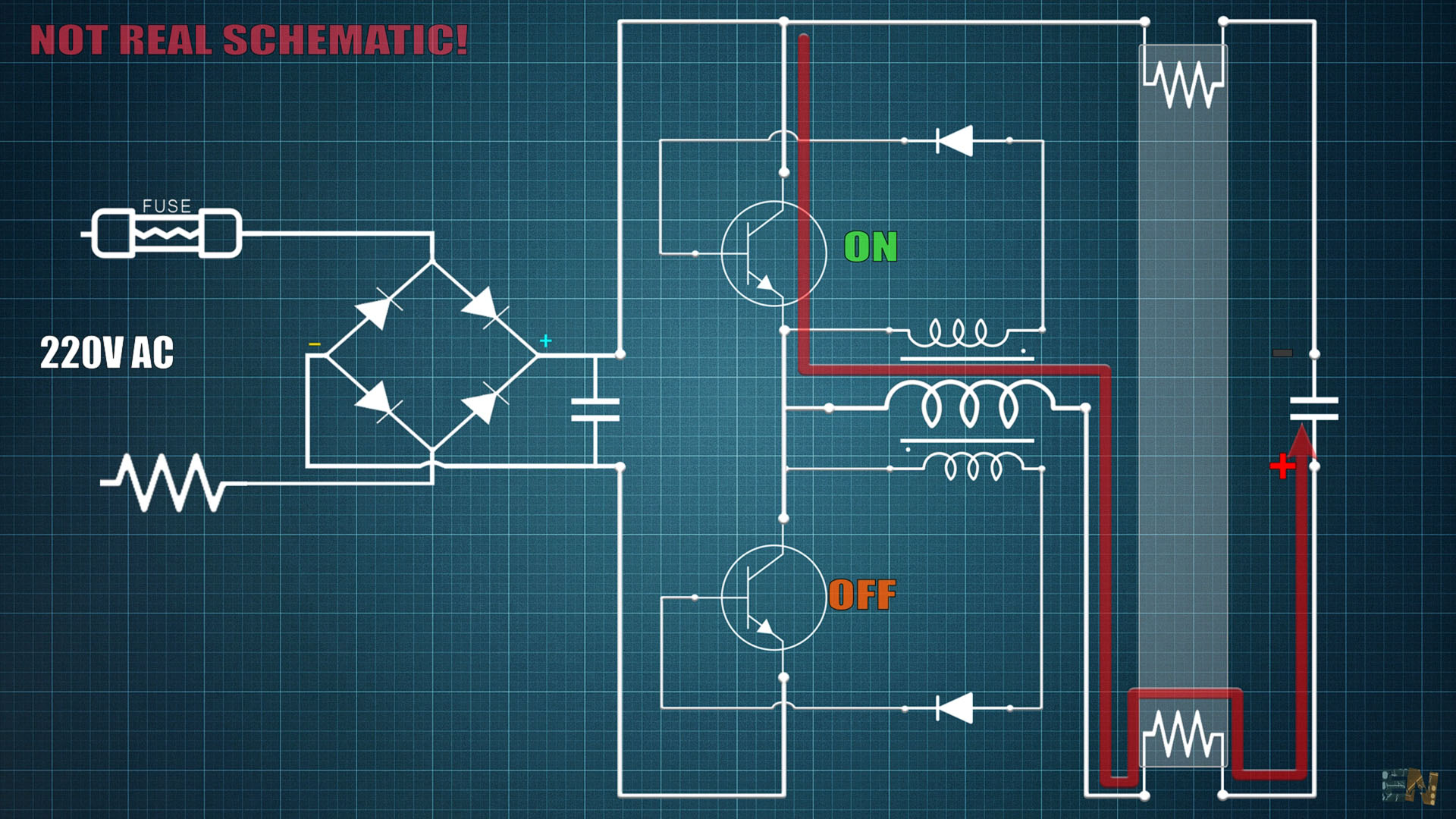
The magnetic field from the coil will collapse and charge the capacitor but with inverted polarity and also higher voltage, since the coil will create high volage spikes. Since the coils are coupled together, this process would change the polarity at the gate of the transistors. So now the top transistor is ON and the bottom one is OFF. That will create a current flow in the reversed direction as you can see below with the red line. The magnetic field will now collapse, charge the capacitor and invert the polarity at the transistors gate once again and the process repeats on and on. That will create a high voltage high frequency signal. This signal is used to power the fluorescent bulb and keep the current of electrons flowing.
That’s basically how the electronic ballast creates high voltage of around 1000V and also high frequency. The frequency created in the CFL ballast is usually from 20 KHz to 80 KHz because is proven that at higher frequency the light emission is better. Once the CFL bulb glows, the voltage across will decreases to 230V and the ballast circuit allows the current to flow through the tube.
I hope that you like this tutorial. If you consider supporting my work, buy my PCBs on my shop, or maybe consider supporting me on PATREON or if you want, make a PayPal donation. Thank you very much.