
Hello! A lot of time has passed since the last Attinys programming tutorial and along the way a new Core (nucleus) appeared to program the small family of Atmel that is much more versatile (Thanks to Franco Arias for passing us this great data!). In addition, the Arduino software improved significantly at its opening, including new facilities for programming other platforms and chips beyond its own products. Hence this update. I hope it will be you useful!
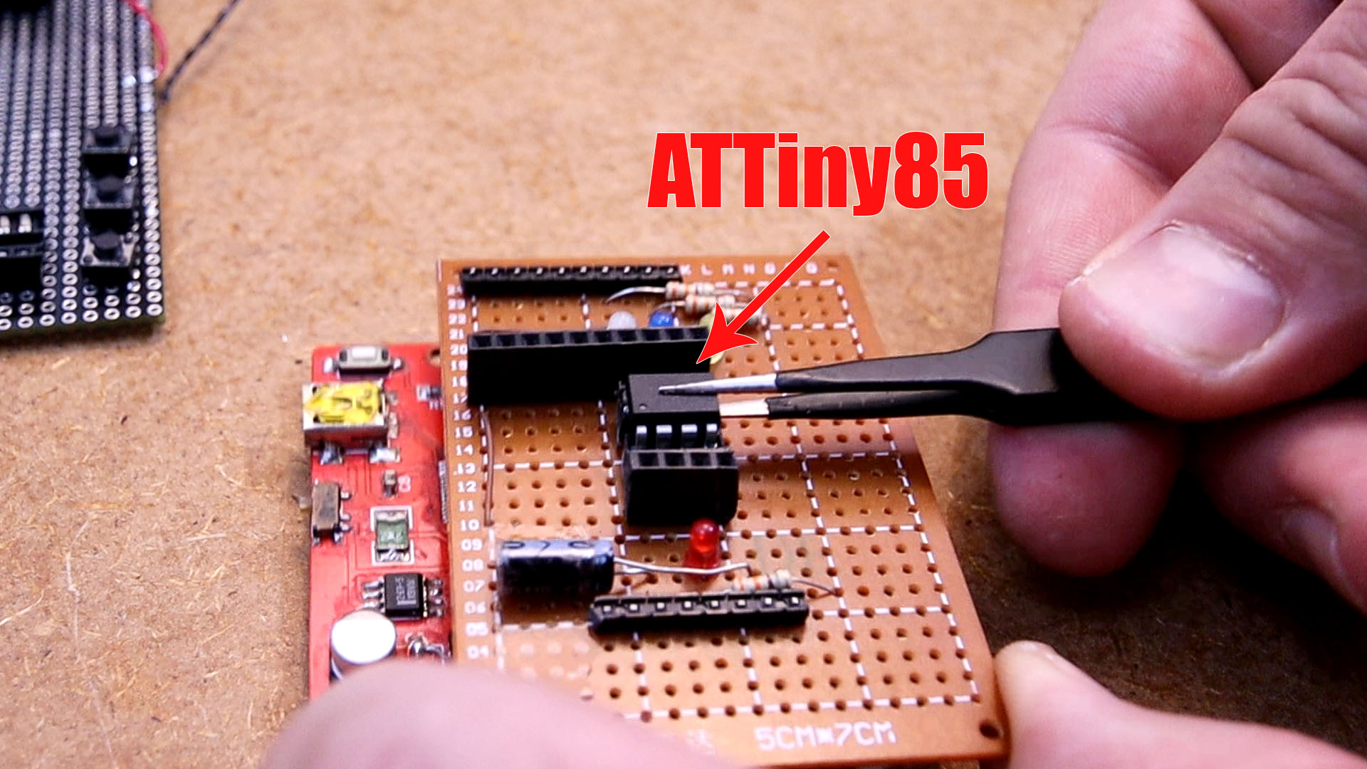
Before we begin, let's refresh the data about the ATTINY25/45/85 family a bit: They are the ideal microcontrollers to do simple tasks that do not require many pins or memory.

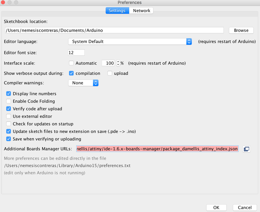
Step 1: Add ATtiny boards to Arduino IDE
By default the Arduino IDE does not support the ATtiny85 it's required to add support for the Attiny85 to the Arduino Board Manager:
Thanks David-one of the Arduino founders for writing the code!
https://raw.githubusercontent.com/damellis/attiny/ide-1.6.x-boards-manager/package_damellis_attiny_index.json
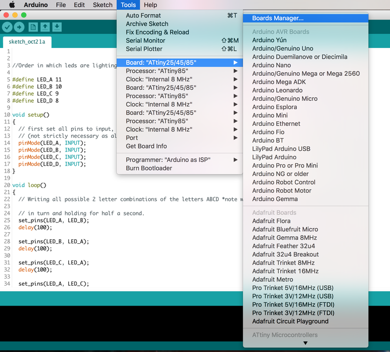
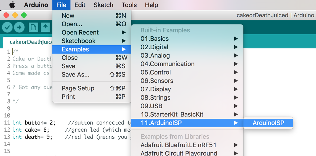
Since what we want is to be able to program the ATtiny85 from the Arduino IDE which requires to burn the bootloader to the ATtiny85 we will need to "prep" the Arduino fist by uploading the ISP sketch to it.
In the Arduino IDE select File-->Examples--> 11. Arduino ISP-->ArduinoISP
the ISP sketch should open and upload it to your Arduino Uno
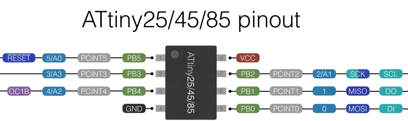
Before the connections are made there is a very important fact to know how pins on microcrontrollers/ICs are labeled.
Pin numbers used to program a chip on the Arduino IDE are based on how the chip manufacturer has internally named/aranged the pins . The manufacturer of the ATtiny85 is ATMEL (the AT in ATtiny85-actually stands for ATMEL);It's common for chips to have the first two initials of the company who makes them.
Pins are gathered into groups called "ports" these ports are labeled A,B,C etc. Each port has a number of pins which are labeled 0,1,2,3 etc and stick out on different parts of the chip which is why a microcontroller's physical pin often time will be different than the pin number used when programming the chip.
An example:
PB0 (in the above datasheet) just means pin 0 is located on Port B of the Chip.
If pin 0 was located on Port A the name would look something like PA0 (Port A pin 0)
To add to the complexity pins can have more than one fuction and be labeled multiple names.
Wrapping it all together! :
Writing a program to light an LED on pin 0 on the ATtiny85 might be confusing at first because just by looking at the chip , there is no pin 0! However, by checking the datasheet of the ATtiny85 from ATMEL-snippet shown above-pin 0 is internally located on the chip's port B (and is actually the chip's physical pin 5 )!
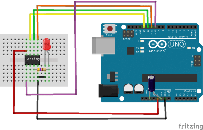
Have an electrolytic capacitor-10uF is recommend but I used a 22uF and it worked fine- to prevent the Arduino from restarting it's self connected to GND & RESET on the Arduino
Use a breadboard and jumper wires to make the connections bellow from the Arduino Uno to the ATtiny85:
Arduino--> ATtiny85

5V            Vcc
GND           GND
Pin 13        Pin 2
Pin 12        Pin 1
Pin 11        Pin 0
Pin 10        Reset
By default any fresh microcontroller chip bought will not be able to be programmed with the Arduino IDE out of the box. This is why it's required to burn the Arduino bootloader onto the chip to make sure the chip will accept any programs uploaded via the Arduino IDE.
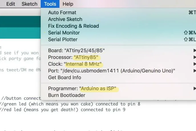
Quick checklist before pressing "burn bootloader"
A message will appear saying "Done Burning Bootloader"
Test that the ATtiny85 can now receive sketches from the Arduino IDE by uploading the blink example
Any request for future tutorials all welcomed! Just leave a comment bellow


