
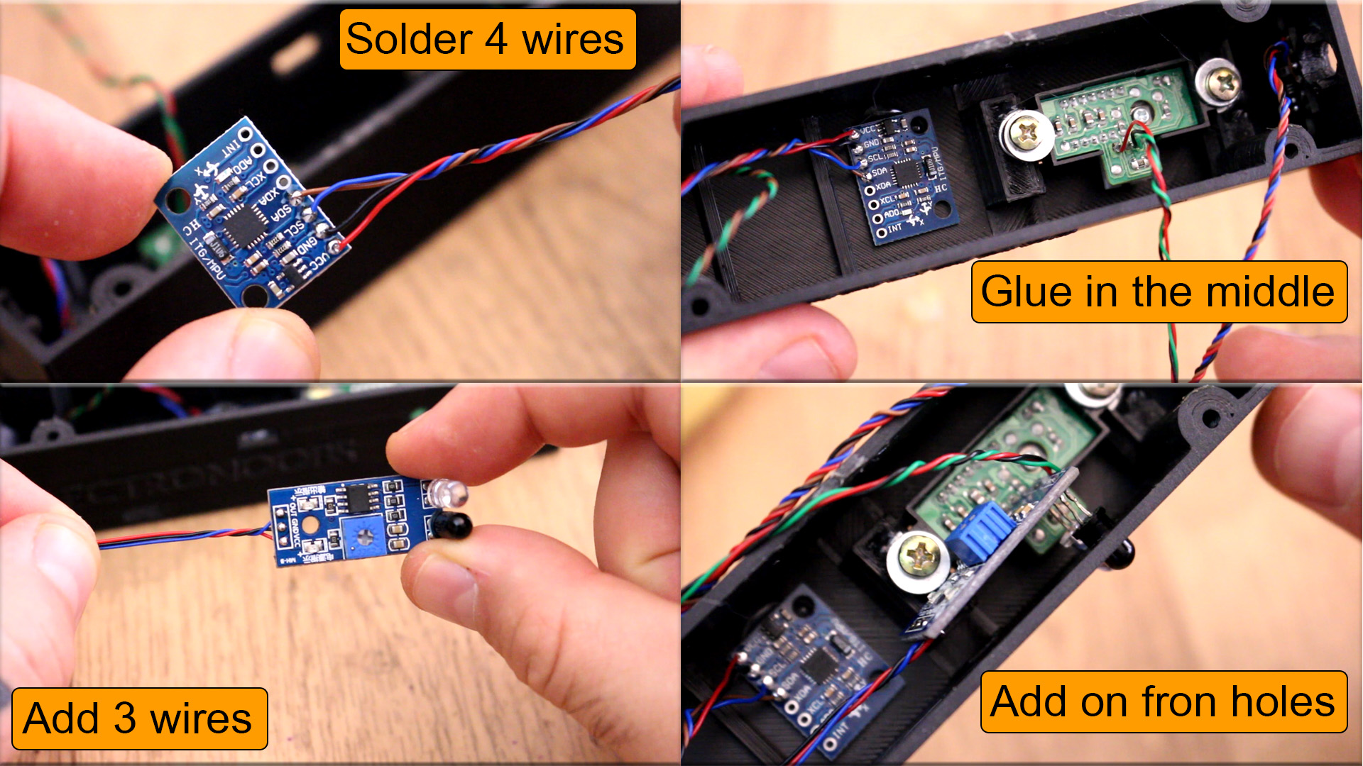
In toder to detect level adn mesure angles we use the MPU6050 IMU module that works with i2c serial communication. Solder ground, vcc, data and clock to this module and glue it in the middle of the case on the bottom part and make sure is aligned with the case walls and quite flat. Next ad 3 wires to the IR sensor and glue that on the front wall of the case, you will se 2 holes there for this sensor. You will need to move the potentiometer of the IR sensor and make sure it will detect the light that's comming back from a white strip placed in front of the sensor. With that we will detect rotations.
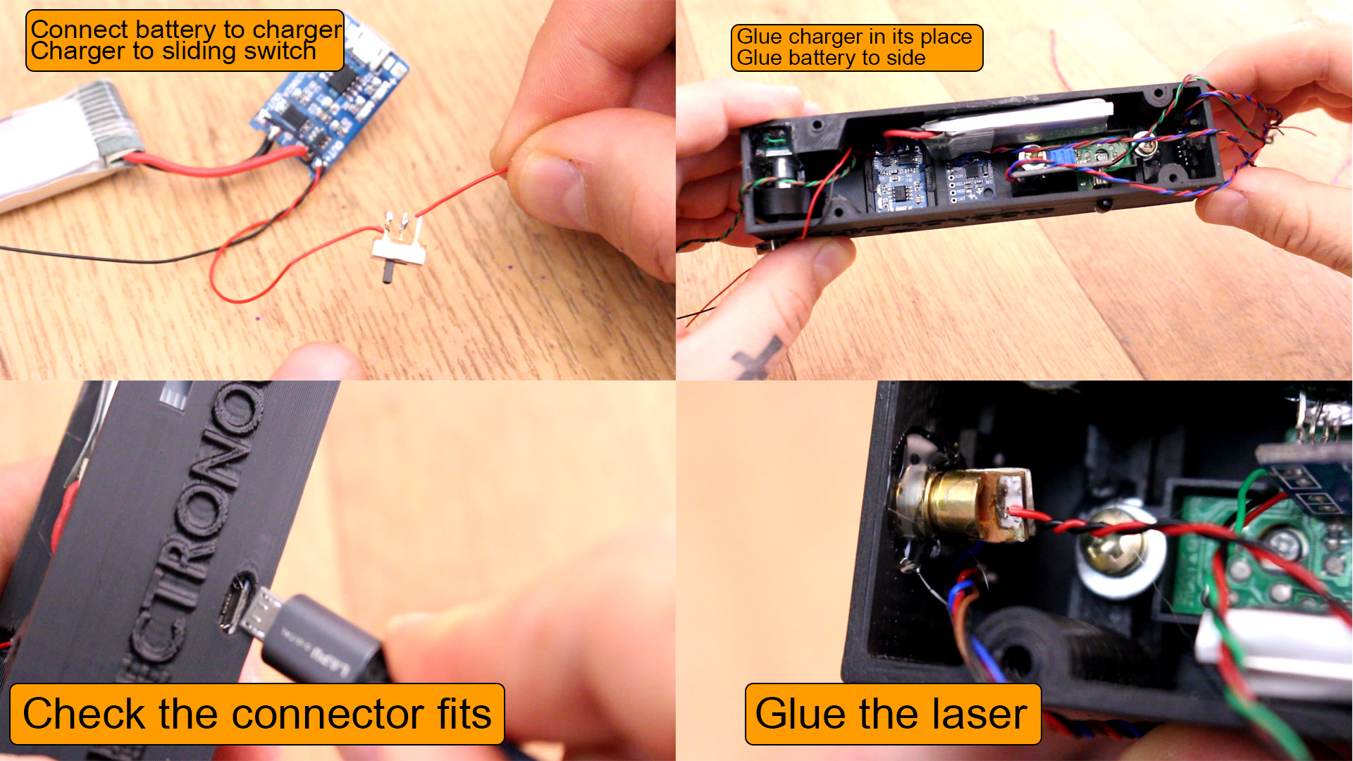
Finally, connect the positive and negative wires from the battery to the B+ adn B- pins of the battery charger. Then connect the positive output to the middle pin of the sliding switch. Also solder a black wire to the negative output from the charger. Glue the switch in its place on the side and the battery charger as well on the bottom side of the case. Check taht the USB connector fits and you could charge the battery. Glue the abttery on the other side and also glue the laser pointer with some hot glue. Is time to connect everything to the Arduino.
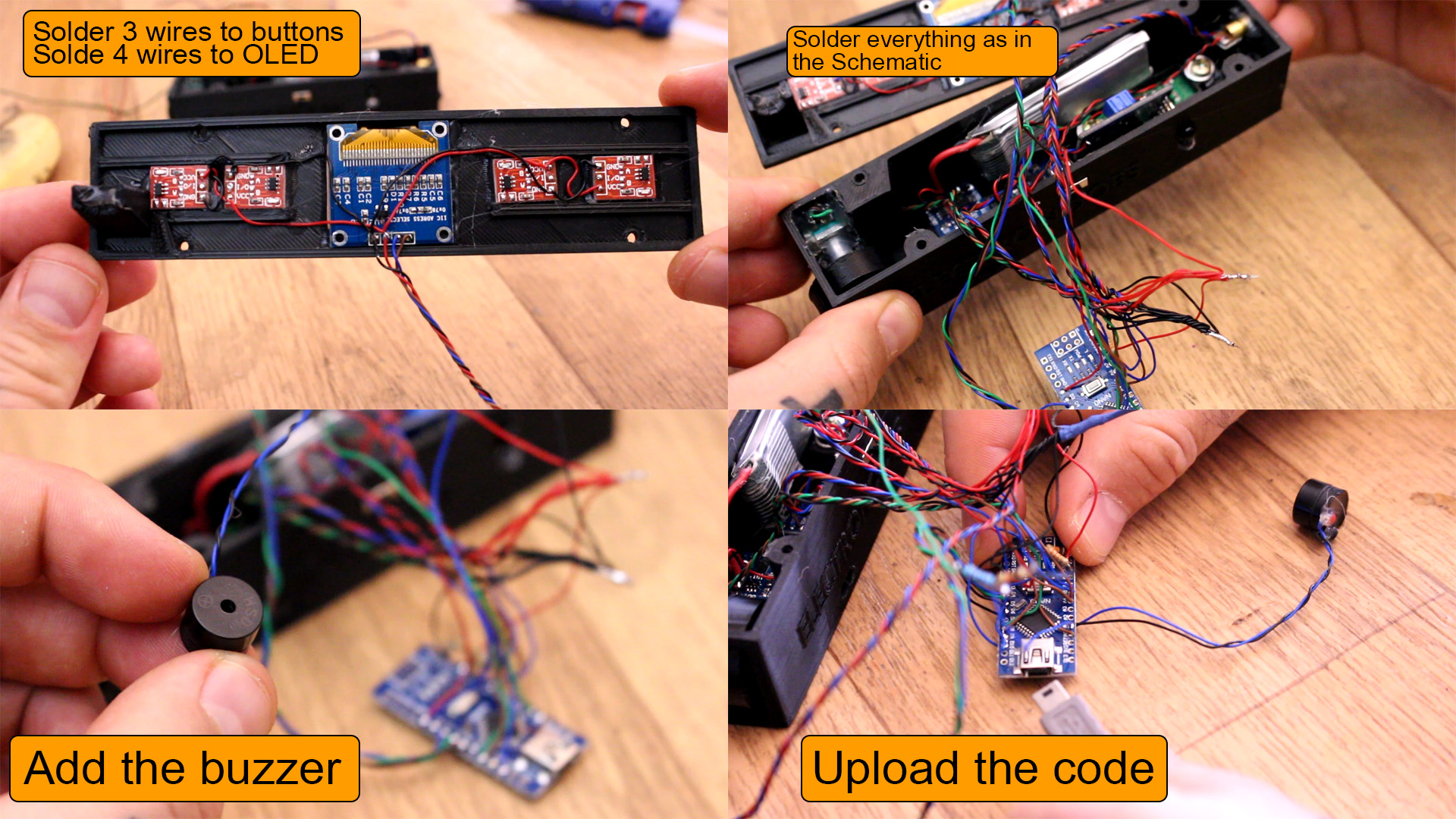
Finally add Vcc, gnd and data wires to 4 capacitive buttons. Glue those as in the photo below on the top part of the 3D printed case. Add wires to the OLED display and glue that on the same part as well. Now connect all the wires to the Arduino as in the schematic. Also add the small buzzer. Finally, go to next part and downlaod the code and uplaod it to the Arduino and test.
The code is long because we have a loot of modes. First inport the libraries taht you could also downlaod from the link below. Install the libraries to your Arduino IDE, downlaod the multi measurement code, compile and uplaod to the Arduino. In the code we define pins and create variables. Then each time we detect the mode button was pushed, we change mode and inside each mode loop we make different measurements. We haev pin state interruption enabeled for pins for the RPM meater and the rotary encoder in order to not miss any step.
//INPUTS/OUTPUTS
#define zero_button 4
#define mode_button 5
#define plus_button 6
#define sound_button 7
#define rot_data 8
//#define rot_clock 9
#define battery_in A0
#define sharp_in A1
#define IR_rpm_in 10
#define laser_out 2
#define buzzer 3
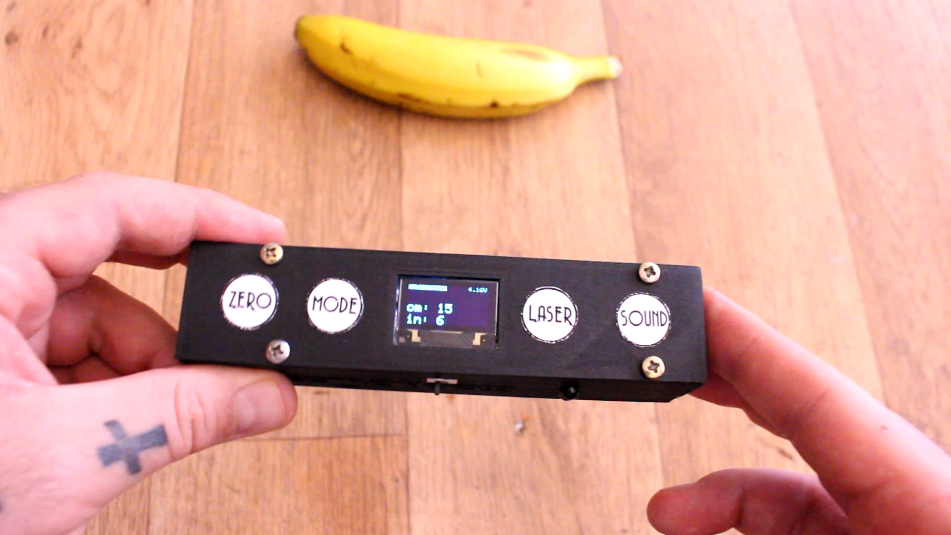
To see all the modes watch the full video below. But we could measure distance, RPM, angle, level adn length. You have the 3D files in this tutorial, the part list, the instructions and the full code if you want to make the same project. Consider supporting my work on PATREON. Thank you.


