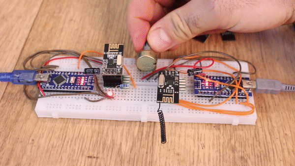
So, I've made a video with some radio modules you could use. In this case we will see the NRF24 radio module. This is using an SPI communication. We have the library for the Arduino IDE, see the connections below, download the example code and test if it works. You need two modules, an LED and a potentiometer and we will send just one byte of data. The range using the amplified module could get up to 700m.
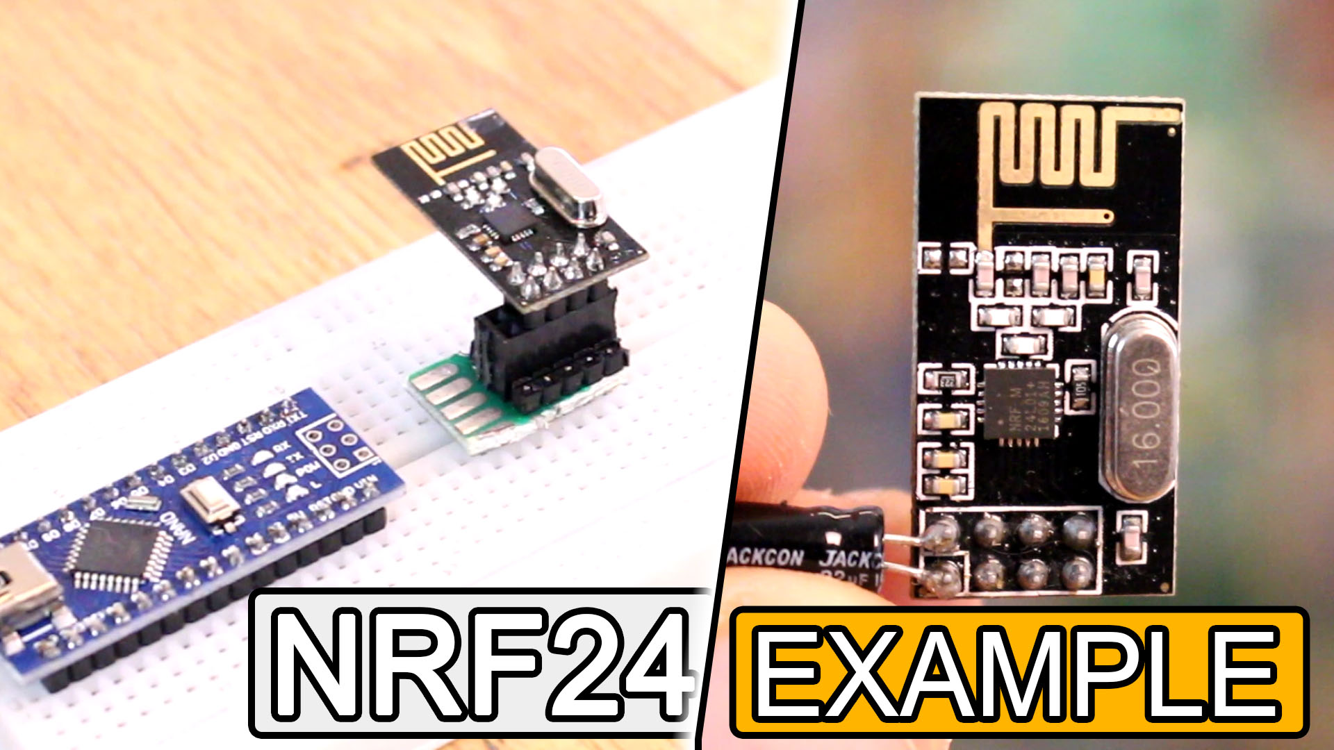
We start this video with the well-known NRF24 radio module. I’ve used this module for years but it has some bad parts as well so let me tell you a little bit about this module. You could but this with the PCB antenna, which basically means this small wire on the PCB will be the antenna. This doesn’t have too much power. In this case, you will also find the SMD version for this module, and this one is a lot smaller and you could solder it directly to your PCB. I’ve used this small module for my last brushed drone project. But, if you want to send data to a longer range, you might need to buy the module with the amplified antenna. This module uses the same radio chip but it also has an amplifier on the board and also has this antenna. The module has 8 pins and those are for power, ground and external interruptions and 5 more pins for the SPI serial communication. For that we need the chip enable, the chip set, mosi, miso and clock pins. Havin an SPI communication makes this module very fast. Usually SPI is a lot faster than i2c or UART serial communication so that’s a plus for his module.
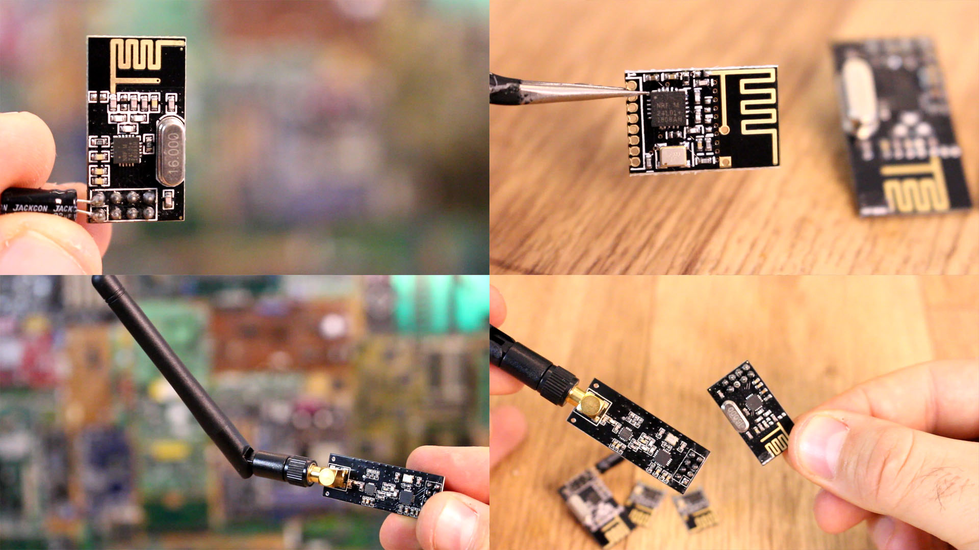
With this module I’ve reached distances of good connection up to 700 meters using my Arduino based radio controller from previous videos. The only thing I don’t like about this module is that it seams to be quite sensible to noise. If I use long wires between the Arduino and the module, I’m almost never able to make a good connection. I also have to wind GND around the MOSI and MISO pins in order to reduce noise for the SPI communication. So is not the radio connection that is sensible to noise, is the SPI communication between the module and the microcontroller. For my projects I usually add short tracks, remove other planes from below or above these tracks, add capacitors at the input, place it on the outside of the board, try to place it far from the DC motors or power converters and so on. And that’s another thing I don’t like. This module works at 3.3 volts. The Arduino usually has a 3.3V supply, but for example with the Arduino NANO, sometimes I'm not able to supply this using the on-board regulator. It doesn’t have enough current output so I always had to add an external 3.3V voltage regulator. You could use this same module as receiver or transmitter or even place them in a constellation and make them talk one to each other.
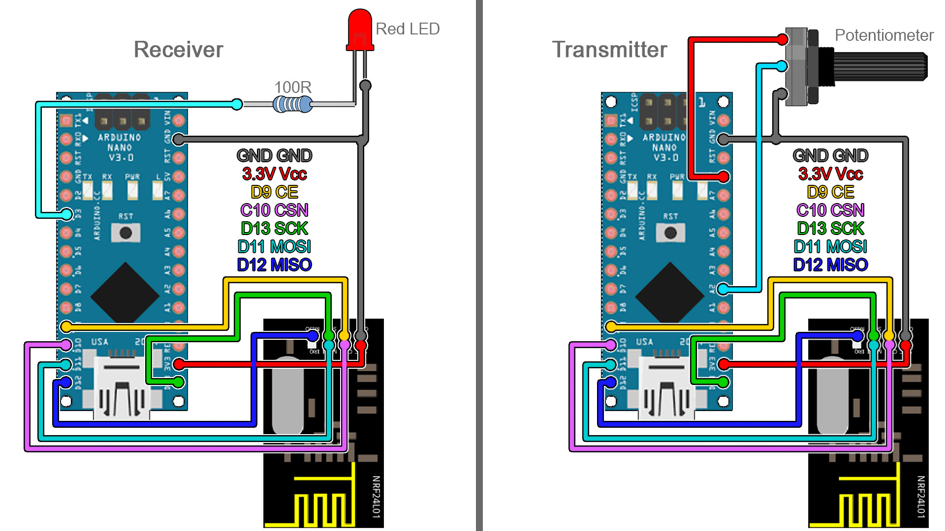
The scheamtic is simple. We haev 2 Arduino NANO and we will use 3.3V from the Arduino in this case. If this doesn't work, connect an external 3.3V supply and share ground. Anyway, connect the SPI pins and add a potentiometer, and LED and a resistor. Upload the codes below to the transmitter and receiver and read the comments in the code for more. Test if it works and you could change the brightness of the LED using the radio connection.
Here we have the transmitter code. Go to the transmitter code link and also download the NRF24 library and install that to your Arduino IDE. Uplaod this code to the Arduino with the potentiometer. Read the comments in the code for more. Copy or download the code from below.
/* 1 ch NRF 24 TRANSMITTER example.
/* Tutorial link: http://electronoobs.com/eng_arduino_tut95.php
 * Code: http://electronoobs.com/eng_arduino_tut95_code1.php
 * Scheamtic: http://electronoobs.com/eng_arduino_tut95_sch1.php
 * Youtube Channel: http://www.youtube/c/electronoobs
 *
  Module // Arduino UNO
    GND    ->   GND
    Vcc    ->   3.3V
    CE     ->   D9
    CSN    ->   D10
    CLK    ->   D13
    MOSI   ->   D11
    MISO   ->   D12
 */

/* First we include the libraries. Download it from
   my webpage if you donw have the NRF24 library */
#include <SPI.h>
#include <nRF24L01.h>             //Downlaod it here: https://www.electronoobs.com/eng_arduino_NRF24.php
#include <RF24.h>
/*//////////////////////////////////////////////////////*/

/*Create a unique pipe out. The receiver has to
  wear the same unique code*/
const uint64_t pipeOut = 0xE8E8F0F0E1LL; //IMPORTANT: The same as in the receiver!!!
/*//////////////////////////////////////////////////////*/

/*Create the data struct we will send
  The sizeof this struct should not exceed 32 bytes
  This gives us up to 32 8 bits channals */
RF24 radio(9, 10); // select  CSN and CE  pins
struct MyData {
  byte pot_value;
};
MyData data;
/*//////////////////////////////////////////////////////*/


//This function will only set the value to  0 if the connection is lost...
void resetData()
{
  data.pot_value = 0;
}

void setup()
{
  //Start everything up
  radio.begin();
  radio.setAutoAck(false);
  radio.setDataRate(RF24_250KBPS);
  radio.openWritingPipe(pipeOut);
  resetData();
}

/**************************************************/

// Returns a corrected value for a potentiometer analog read
// It will map the value from 0 to 1024 to 1 to 255
int mapPotentiometers(int val, int lower, int middle, int upper, bool reverse)
{
  val = constrain(val, lower, upper);
  if ( val < middle )
    val = map(val, lower, middle, 0, 128);
  else
    val = map(val, middle, upper, 128, 255);
  return ( reverse ? 255 - val : val );
}

void loop()
{
  data.pot_value = mapPotentiometers(analogRead(A2), 0, 512, 1024, true);
  radio.write(&data, sizeof(MyData));
}
Here we have the receiver code now. Go to the receiver code link and also download the NRF24 library and install that to your Arduino IDE in case that you haven't done that yet. Uplaod this code to the Arduino with the LED. Read the comments in the code for more. Copy or download the code from below.
/* 1 ch NRF 24 TRANSMITTER example.
/* Tutorial link: http://electronoobs.com/eng_arduino_tut95.php
 * Code: http://electronoobs.com/eng_arduino_tut95_code2.php
 * Scheamtic: http://electronoobs.com/eng_arduino_tut95_sch1.php
 * Youtube Channel: http://www.youtube/c/electronoobs

  Module // Arduino UNO
    GND    ->   GND
    Vcc    ->   3.3V
    CE     ->   D9
    CSN    ->   D10
    CLK    ->   D13
    MOSI   ->   D11
    MISO   ->   D12
 */

/* First we include the libraries. Download it from
   my webpage if you donw have the NRF24 library */
#include <SPI.h>
#include <nRF24L01.h>             //Downlaod it here: https://www.electronoobs.com/eng_arduino_NRF24.php
#include <RF24.h>
/*//////////////////////////////////////////////////////*/

/*Create a unique pipe out. The receiver has to
  wear the same unique code*/
const uint64_t pipeIn = 0xE8E8F0F0E1LL; //IMPORTANT: The same as in the receiver!!!
/*//////////////////////////////////////////////////////*/

/*Create the data struct we will send
  The sizeof this struct should not exceed 32 bytes
  This gives us up to 32 8 bits channals */
RF24 radio(9, 10); // select  CSN and CE  pins
struct MyData {
  byte pot_value;
};
int LED = 3;
MyData data;
/*//////////////////////////////////////////////////////*/

//This function will only set the value to  0 if the connection is lost...
void resetData()
{
  data.pot_value = 0;
}

/**************************************************/

void setup()
{
  pinMode(LED,OUTPUT);
  Serial.begin(9600); //Set the speed to 9600 bauds if you want.
  //You should always have the same speed selected in the serial monitor
  resetData();
  radio.begin();
  radio.setAutoAck(false);
  radio.setDataRate(RF24_250KBPS);
  radio.openReadingPipe(1,pipeIn);
  //we start the radio comunication
  radio.startListening();
}

/******Reset the received data to 0 if connection is lost******/
unsigned long lastRecvTime = 0;
void recvData()
{
  while ( radio.available() )
  {
    radio.read(&data, sizeof(MyData));
    lastRecvTime = millis(); //here we receive the data
  }
}
/**************************************************************/

void loop()
{
recvData();
unsigned long now = millis();
//Here we check if we've lost signal, if we did we reset the values
if ( now - lastRecvTime > 1000 ) {
// Signal lost?
resetData();
}

Serial.print("Potentiometer: "); Serial.println(data.pot_value);
analogWrite(LED,data.pot_value);

}
Now you are able to control the LED using radio connection. Using the amplified antenna module this would be the same. The scheamtic and code is the same. That's it for this module. I hope you are able to use it. If not, comment below and ask for help. Keep up!