See my last poroject on this link about another attempt that I had on digital power suplly. In that case, the TFT display made everything very slow so I had to use another type of display. In this case we use a simple LCD to print the values. The circuit is simple. We lower the voltage from 230V to around 26V AC, then we rectify it with a full bridge, then we use a buck converter to vary the output digitally.
You have the schematic for this project below. You need the Arduino, the ADS1115 ADC module, the OLED display, the ACS712 current module, the TP4056 based charger and a few more components. You have all the values below. After you make the connections, you can downlaod the code and upload it to the Arduino and give it a test.
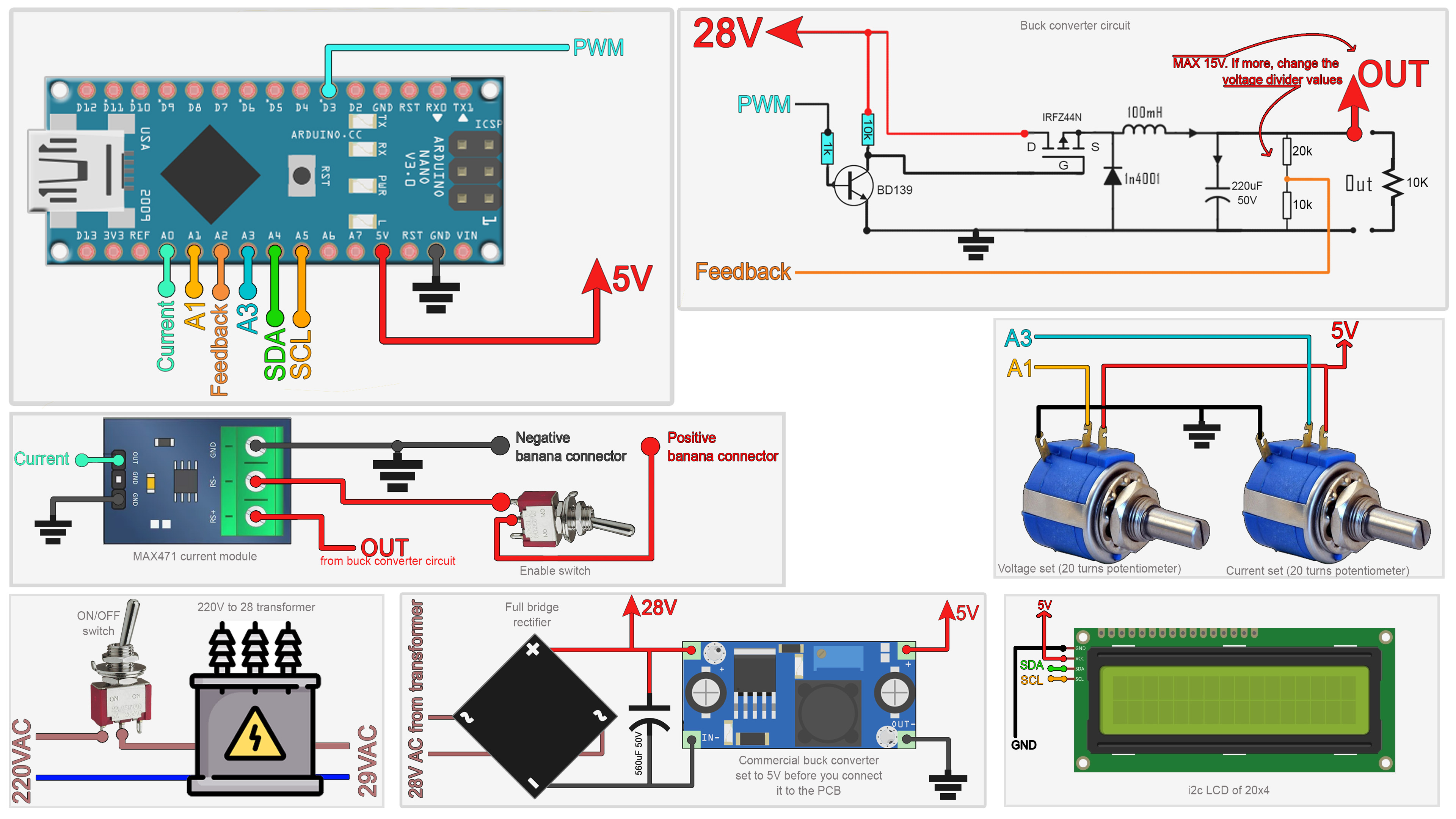
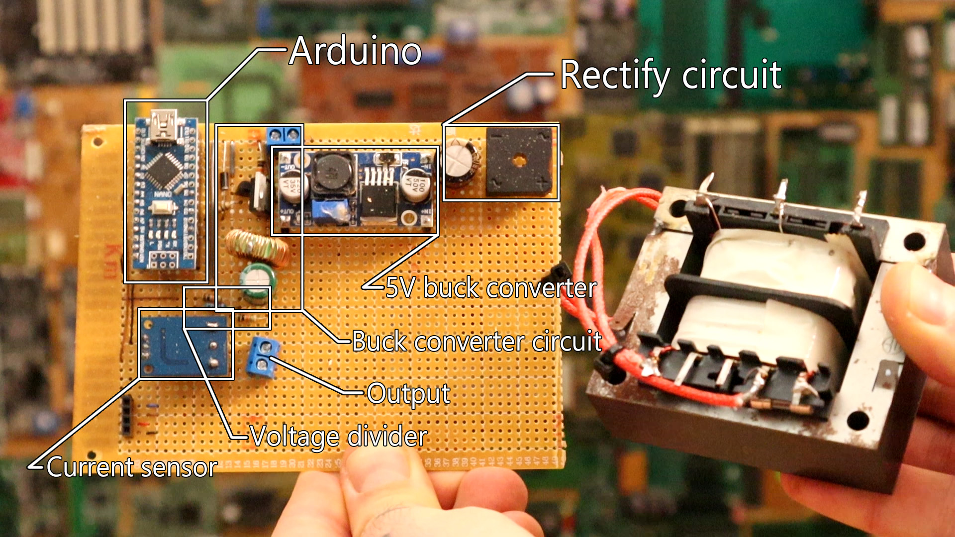
We start with the transformer connected to the full rectifier. Once we haev 28V DC, we connect that to the 5V buck converter but also to the input of the buck converter circuit. The 5V converter will supply the digital part, Arduino and LCD.
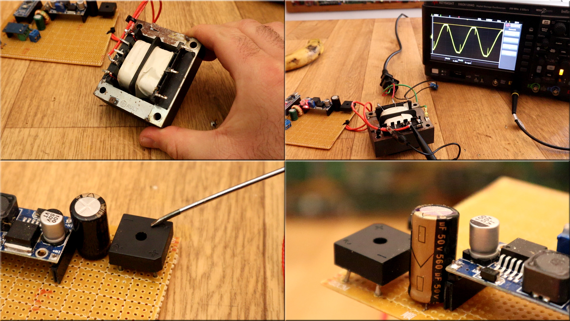
We swtart by reducing the voltage. Here in Spain the main voltage is of 230V. We use a transformer to lower that voltage to 26V. But this is still AC voltage and we nee DC. For that, we need a FULL BRIDGE RECTIFER and we get only the positive side of the AC signal. But, if we place a big capacitor at the output we can smooth those peaks and get steady DC volage.
Above you can see how the signal is rectified. But the signal is still AC but only with the positive side. That's why we add a capacitor at the output and get steady DC. Below you can see my Transformer, the rectifier and a big capacitor.
Ok, now we have our main 28V DC supply and the small buck converter module give us 5V for the Arduino and the LCD screen. Now we need to vary the output voltage. We do that with another buck converter circuit, but this one is controlled by the Arduino with a PWM signal. See my tutorial on buck converters here on this video.
As you can see on the schematic, on the output of the buck converter circuit, there is a voltage divider. That will lwoer thge value fromk a maximum of 15V in this case, to under 5V so the Arduino analog input could read that. That is our feedback for voltage.
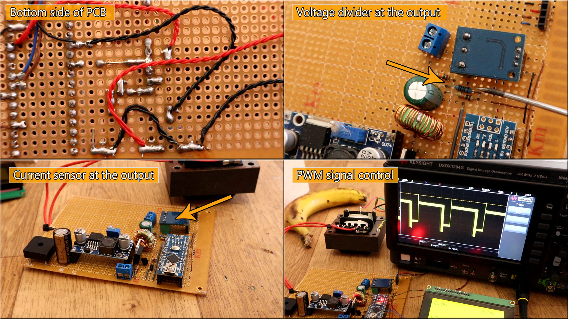
At the same tiem we have the current sensor at the outpiut and that is our feedback for current values. With this two feedbacks we can create out PID code and control a PWM signal applied to the MOSFET of the buck converter circuit and by that, control the output voltage. We set a value on the screen for voltage and current. If the output is higher, we change the PWM signal till the voltage is the same and we do the same for current.