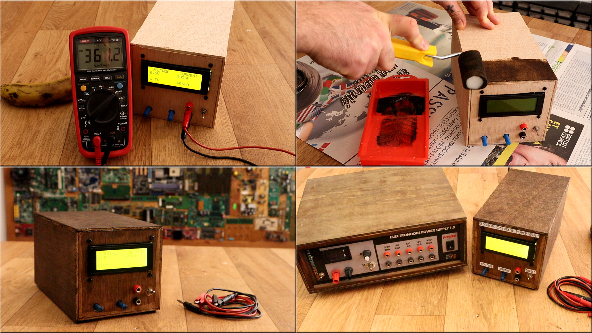
Ok, finally we connect everything to the PCB, the LCD, the potentiometer and we add a load at the output. Next, I uplaod the code that you will find below on the next part. I now test the output with a multimeter in order to see if I get the same values for voltage and current.
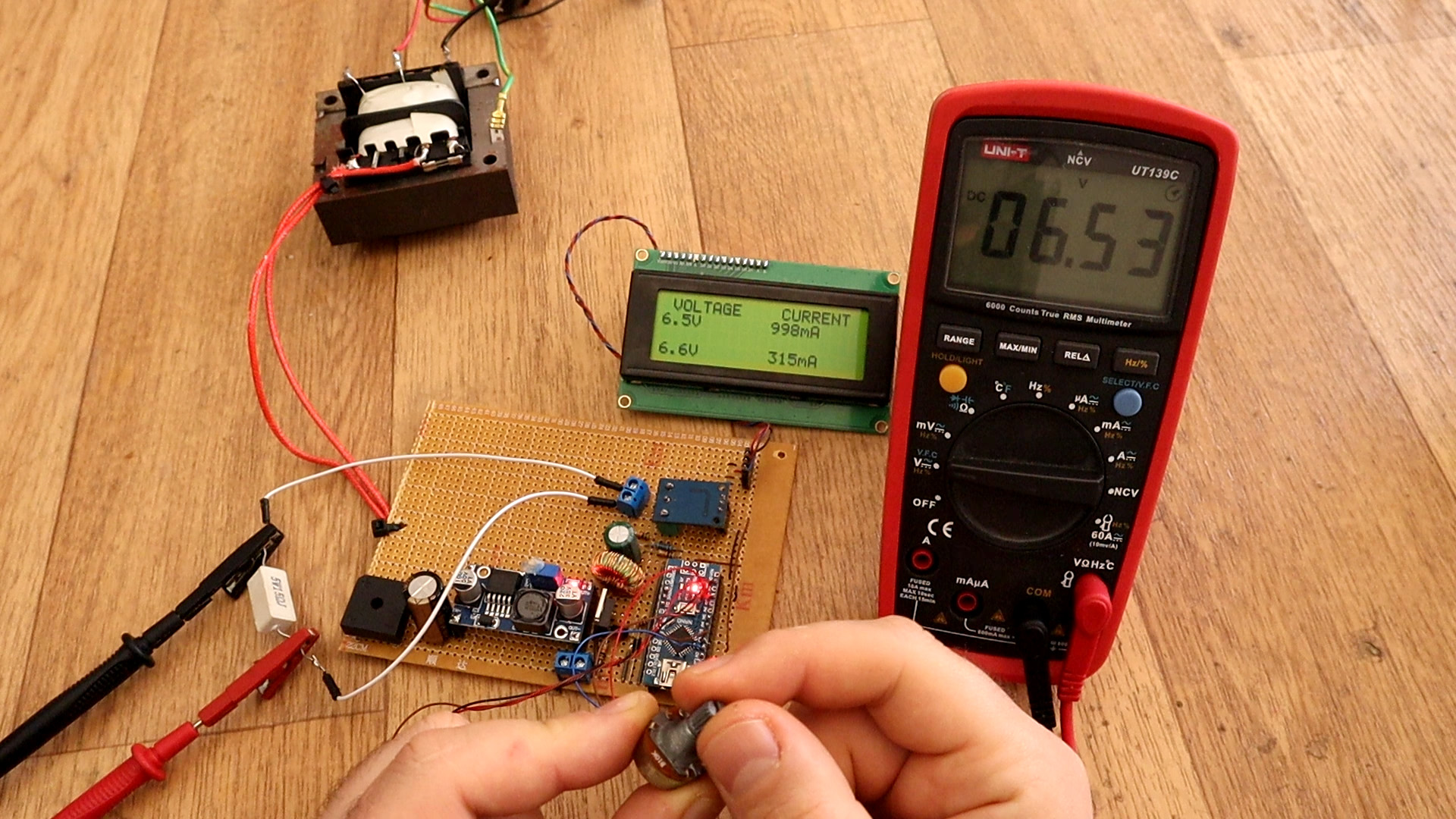
Now we have everything connected.
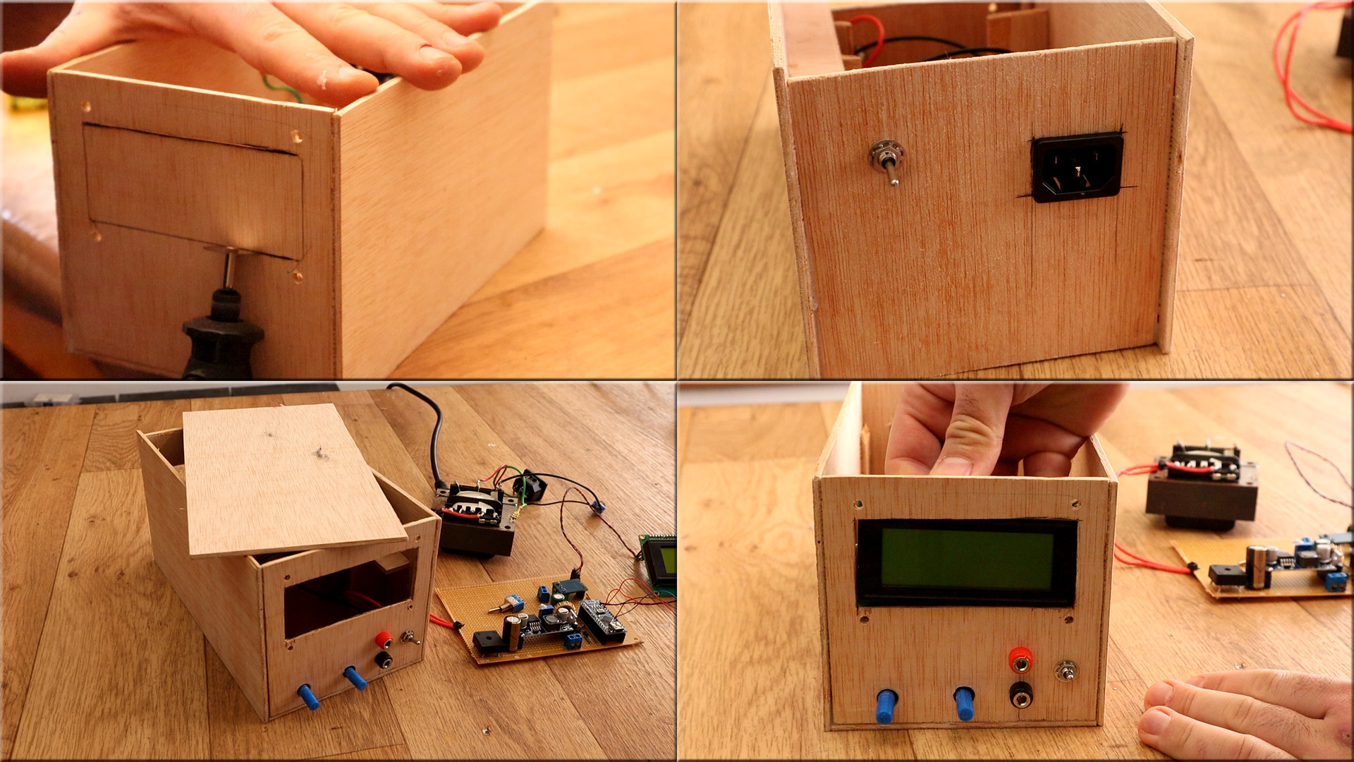
I first wanted a 3D case which by the way, you could dwonlaod from below. But printing time was very long. So, I've decided to make one out of plywood just as in my past vintage look power supply project. I've made measurements and glue the parts with some white glue. Then I've cut out holes for the LCD, the main input, swithces and bannana connectors.
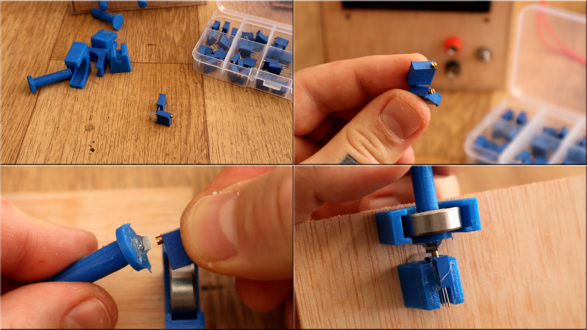
You see those blue plastic knobs in the photo above? I wanted 10 turns potentiometers but I only had those small format potentiometers. So, I printed some suports and some plastic knobs and made my own big 10 turns potentiometers as you can see in the picture below. So, download from below the STL files for the knob and print them uisn PLA material and 20% infill.
Finally, after I fit everything inside and glue the case, I use some dark varnish and paint the case. Now it has a better and more vintage look. Try and buy the yellow screen because if you ahev the blue display, it won't look too vintage. And that's it. You have all you need to build this on this tutorial. The case, the schematic, the code and part list. Consider supporting me on PATREON here on this link.