


Last year I’ve made two door lock projects. One was the keypad project and the second one was an RFID door lock project each with a 3D printed case and a servo to open the door. Today I have a new one and probably the last door lock project on this channel. This is a fingerprint door lock with a black box integrated. So, why is this better than the other two projects? Well, first you don’t need to carry any key or card with you since you always have your fingerprint. So that’s more convenient. It is also faster to use than typing the code of the keypad door lock. Just place the finger and open the door. Also, it is almost impossible to trick this door lock since a fingerprint is difficult to copy so with a metal case instead of plastic, this would be a very secure door lock. It also has a black-box with SD card and real time clock so we could see the log line by line with everything that happened with the door.
First we need to see how to use the fingerprint sensor by itself. Then we will create the rest of the project. When you receive the fingerprint module, it has no fingerprints stored to its memory so first we have to add our data. Connect it like below (left) to and Arduino UNO, or like (right) to and Arduino MEGA. Not all pins are good for this since not all pins could create interrupt for the RX pin so follow the schematic below. For this example, we will use the serial monitor to save our fingerprint to the sensor database. Upload the example code below called, fingerprint scan example.
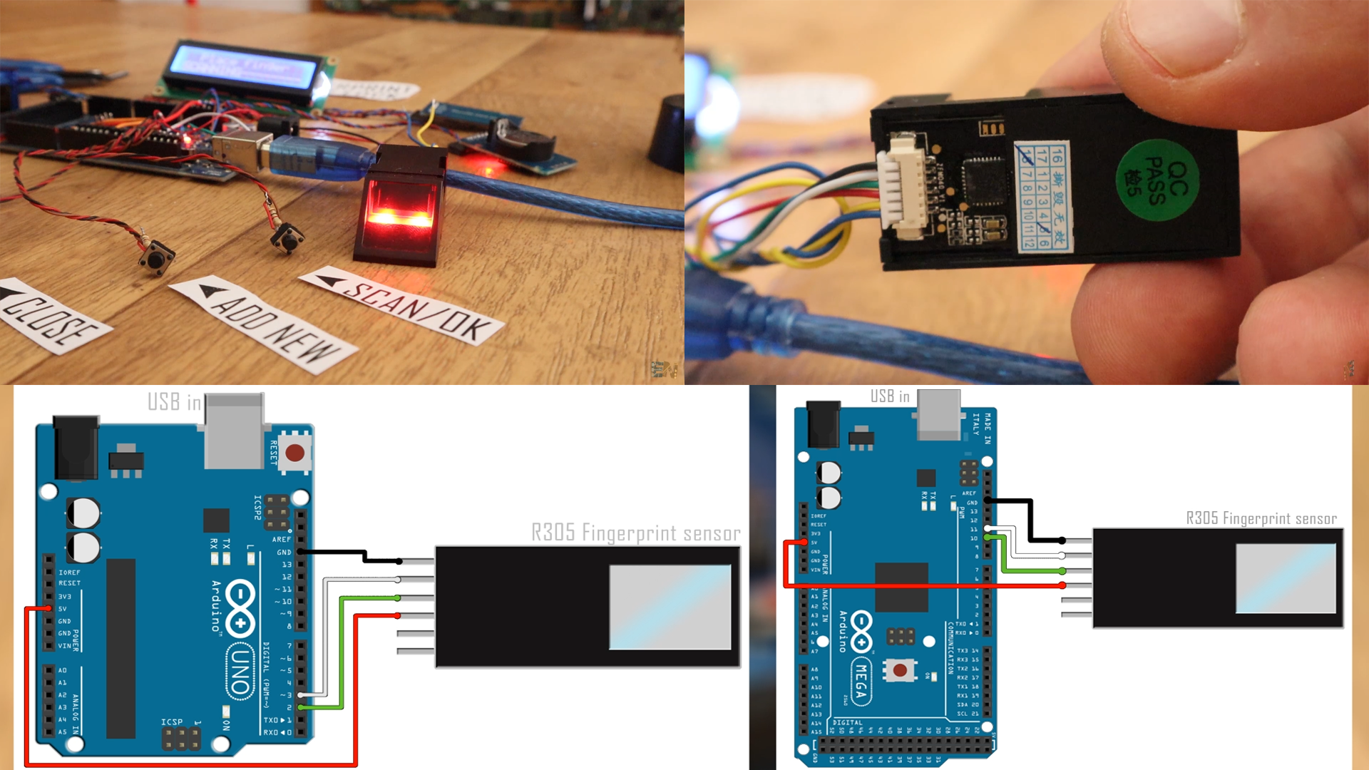
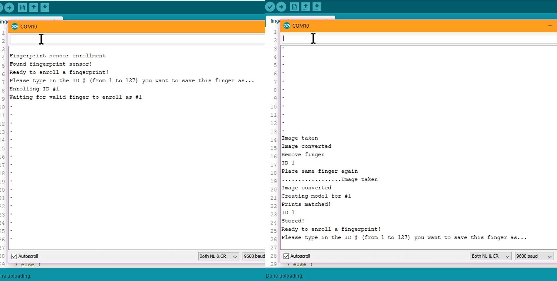
Make sure you install the adafruit fingerprint library that you could also find below. Upload this example code to the Arduino and open serial monitor and select the 9600 baud rate. Now sent the ID number where you want to store the new fingerprint. I send 1 since I want to save my first print to the ID 1 which will be the main user. Type 1 and press enter and follow the instructions. Scan the finger once, remove it and scan it once again and the new data is stored.
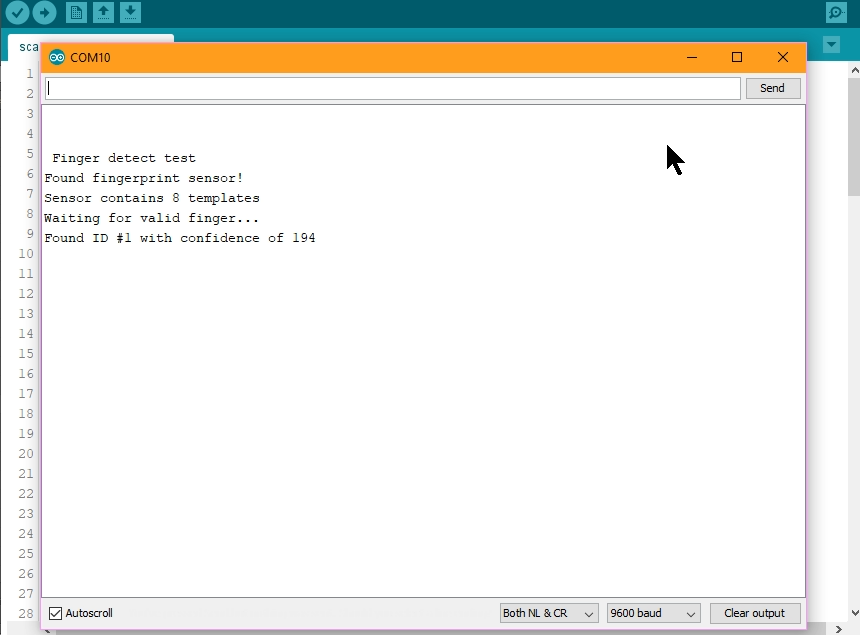
Now, you have another small example code that will detect the scanned fingerprint. With the same schematic before, upload the scan fingerprint example code you can find below. Open the serial monitor and place your finger on to the sensor. There you have it. ID1 was detected, which is the ID for the finger scaned before. With these two codes you now know how to store and read data from the sensor. Read the comments in the code for more.
Now, let’s configure the real time clock. This module has its own battery so even when the Arduino is not powered, it will still keep the real time for more than a year. But first, we have to tell it the real time. Connect it below this to the Arduinos i2c port. Now open the set time example code from below and make sure you install the DS32 31 library you will also find below.
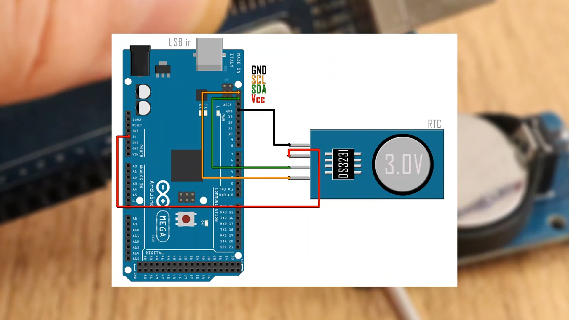
Here in the code below, uncomment the 3 lines in the setup loop and add the exact date and time. Add the day, month, year and then the hour, minute and seconds and upload the code. Then comment back the lines and upload the code once again.
// DS3231:  SDA pin   -> Arduino UNO: A4 pin / Ardunino MEGA: SDA pin
//          SCL pin   -> Arduino UNO: A5 pin / Ardunino MEGA: SCL pin
#include <DS3231.h>     //Downlaod library here: https://www.electronoobs.com/eng_arduino_ds3231.php
DS3231  rtc(SDA, SCL);

void setup()
{
  // Setup Serial connection
  Serial.begin(115200);
  // Uncomment the next line if you are using an Arduino Leonardo
  //while (!Serial) {}

  // Initialize the rtc object
  rtc.begin();

  // The following lines can be uncommented to set the date and time
  //rtc.setDOW(MONDAY);     // Set Day-of-Week to SUNDAY
  //rtc.setTime(11, 47, 0);     // Set the time to 12:00:00 (24hr format)
  //rtc.setDate(28, 8, 2018);   // Set the date to January 1st, 2014
}

void loop()
{
  // Send Day-of-Week
  Serial.print(rtc.getDOWStr());
  Serial.print(" ");

  // Send date
  Serial.print(rtc.getDateStr());
  Serial.print(" -- ");

  // Send time
  Serial.println(rtc.getTimeStr());

  // Wait one second before repeating :)
  delay (1000);
}
Open serial monitor, and there you have it, this is the real time you get from the sensor and all you have to do is to use the get time and get date functions of the DS32 31 library. So, now we know how to use the RTL module as well.

We already seen how the SD card module works in the 3D scanner tutorial. Check that video for more details. You need to install the SD library you will find below as well. Using the SD open and SD print function we can write data to the SD card in an txt format.
That’s it. Now the final code is quite long. I’ve placed comments to help you understand it. The main idea goes like this. The buttons will activate the loops for scanning, adding new user or close the door. After each loop, there is an SD card log print and in each SD print, we read the real time. Mount the enxt schematic below and then upload the final code and gieve it a test.
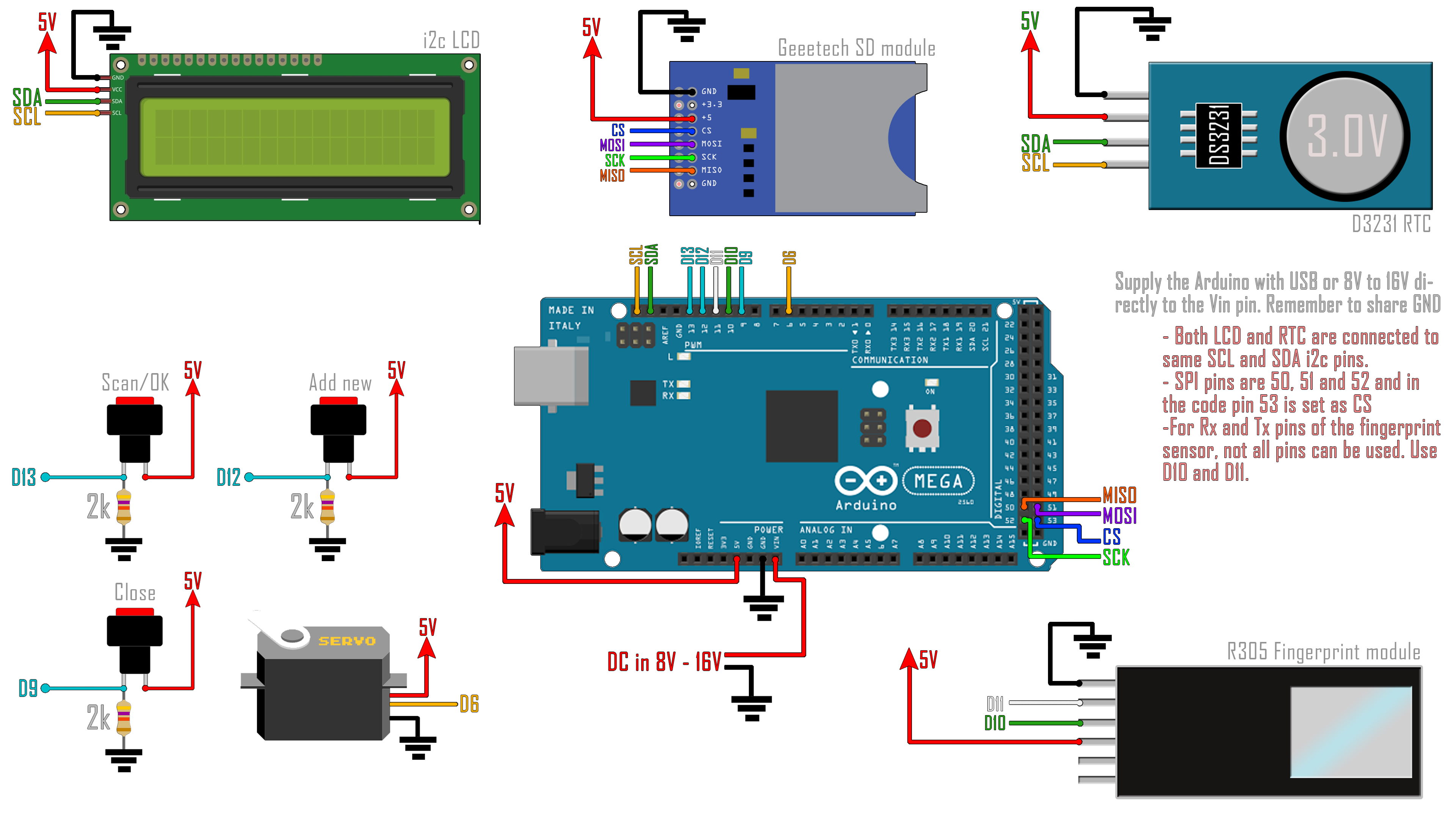
Below the void loop, we have two functions. One is to scan the finger and the other is to add new user to the database. In the bit of code below you can change which ID is the main user, in my case is ID 1 and only this ID can add new users. Also, there is the maximum and minimum angle of the servo motor for open and close the door. Change these values in case you need others angle. That’s it, upload this code to the Arduino mega and make sure you have this schematic for the final project.
/////////////////////////////////////Input and outputs////////////////////////////////////////////////
int scan_pin = 13;			//Pin for the scan push button
int add_id_pin = 12;		//Pin for the add new ID push button
int close_door = 9;			//Pin to close the door button
int green_led = 8;			//Extra LEDs for open or close door labels
int red_led = 7;
int servo = 6;				//Pin for the Servo PWM signal

//////////////////////////////////////////////////////////////////////////////////////////////////////
//////////////////////////////////////Editable variables//////////////////////////////////////////////
//////////////////////////////////////////////////////////////////////////////////////////////////////
int main_user_ID = 1;                 //Change this value if you want a different main user
int door_open_degrees = 180;
int door_close_degrees = 0;
//////////////////////////////////////////////////////////////////////////////////////////////////////


