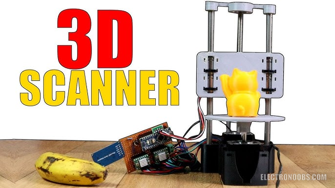
What’s up my friends, welcome back. Almost all of my DIY project have a 3D printed case of some sort of printed part. To print an object, you first need the 3D file. You have the file, you print the object. This project will do just the opposite, you have the object you get the 3D file. This machine should be able to 3D scan small objects with dimensions up to 13cm in the x and Y directions.
by: ELECTRONOOBS on 2026-07-11
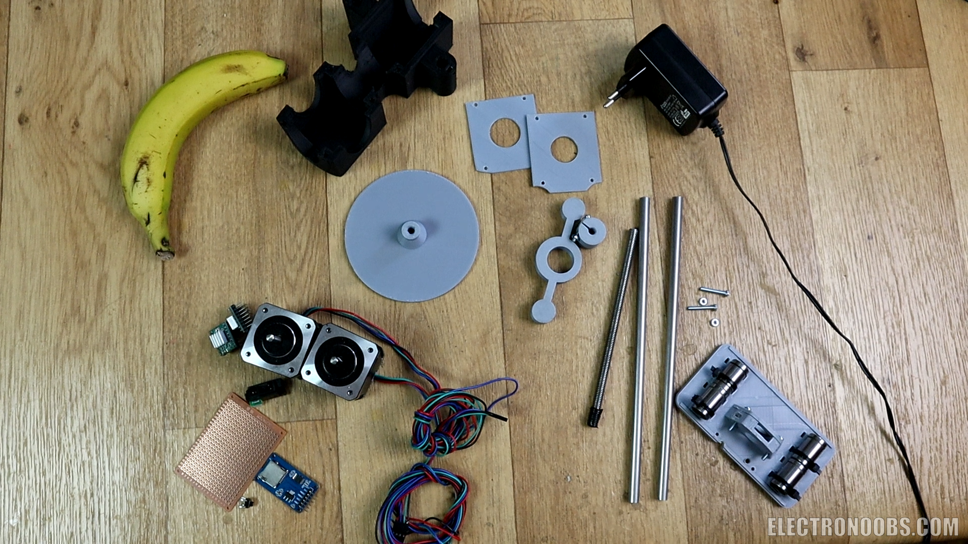
1 x Arduino NANO/UNO LINK eBay
1 x Sharp 0A51SK: LINK eBay
2 x A4988 driver: LINK eBay
2 x NEMA17 motors: LINK eBay
1 x SD module: LINK eBay
1 x 12V-2A power supply: LINK eBay
1 x screw PCB connector: LINK eBay
Female pins: LINK eBay
1 x micro-SD card: LINK eBay
1 x drilled PCB: LINK eBay
2 x 47uF cap: LINK eBay
1 x limit switch: LINK eBay
Wires LINK eBay
2 x smooth rods (200mm/8mm): LINK eBay
4 x LM8UU bearing: LINK eBay
1 x lead screw (200mm/8mm): LINK eBay
M3 screws: LINK eBay
Wire, soldering iron, solder, etc...
Below you can find a link for the STL files for the frame. Download it and print the files using your 3D printer. I've used 2 perimeters, 20% infill, 0.4mm nozzle and 0.2mm layer height. I've printed the files using PLA material, a 0.4mm nozzle, 0.2mm layer height and 20% infill and my CREALITY CR10 printer. All files are aready oriented so you don't have to rotate them, just open them in Reperier or Cura and slice them and print!
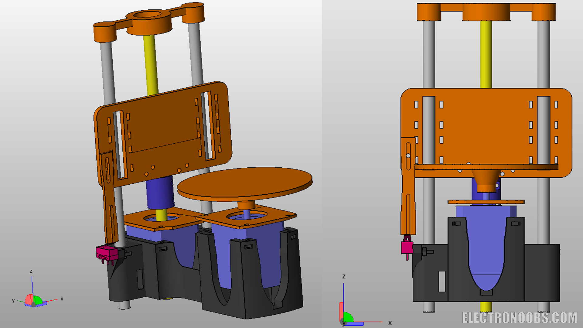
Follow this steps and build the frame. Place the two NEMA17 motors in place on the frame base. Fix them in place with M3 screws and the printed top parts. Now, fit in place the two smooth rods. Prepare the Z-axis carrige with the linear bearings. Use zip ties and fit those in place and then, add a 8mm nut on the back.
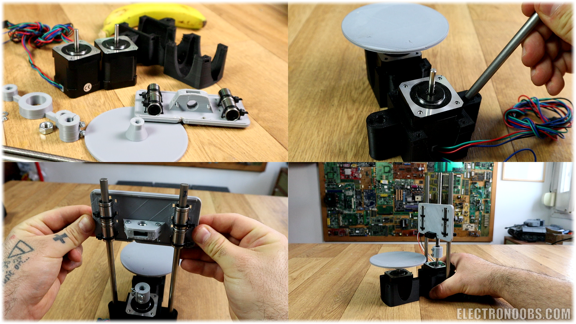
Now place the carrige on the smooth rods, add the plastic pulley on the shaft of the motor and put the threaded rod or lead screw. Finally, add the turntable on the front motor.
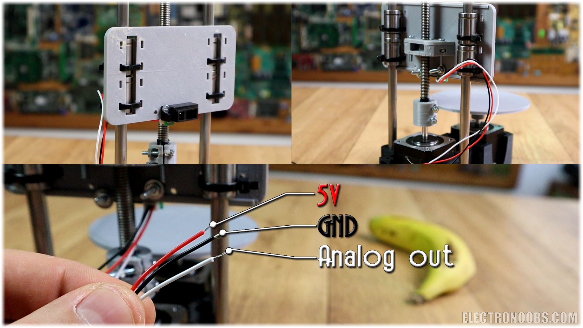
The sensor will give a direct analog output according to the measured distance. Finnaly, add (or not if using no homming code) the limit switch for the Z-axis. This limit swithc is used to home the axis at the beggining of the code loop when we start the machine. The frame is ready.
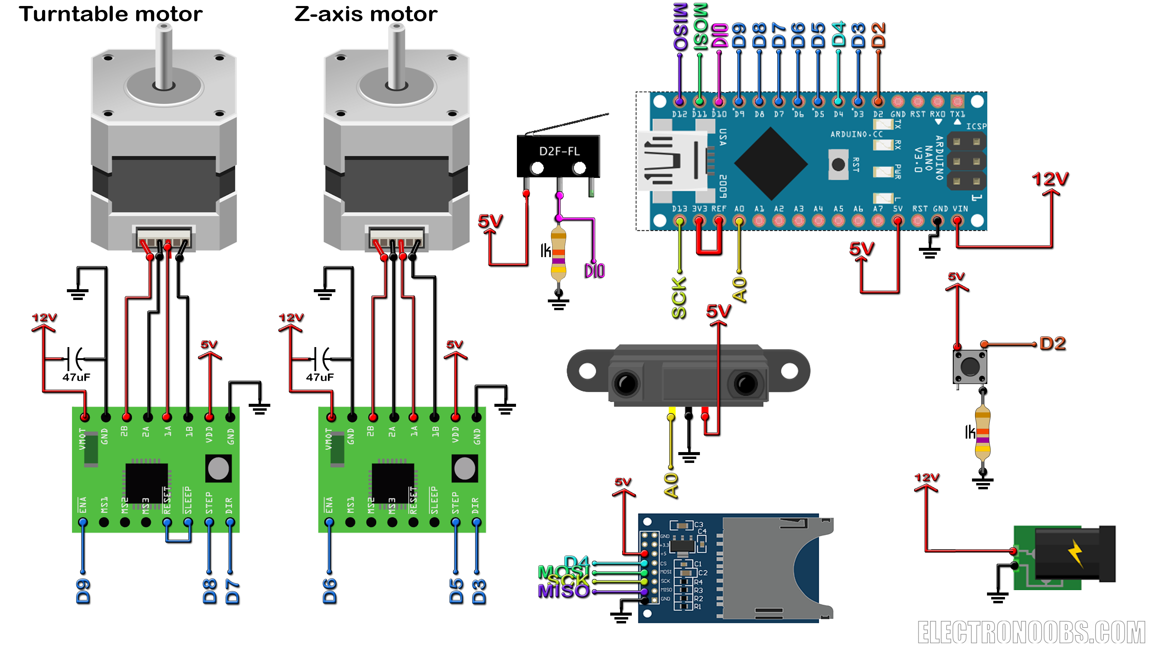
This below is what we need for the electronics part. The schematic is with an end stop limit switch. If you don't want to use it, make sure to later upload the code without limit switch. The push button is used to start the scanning process. Remember to connect Vref to 3.3V. We do that because the amximum voltage of the sensor is 2.4V. To increase precision, we use external voltage refference for the ADCs.
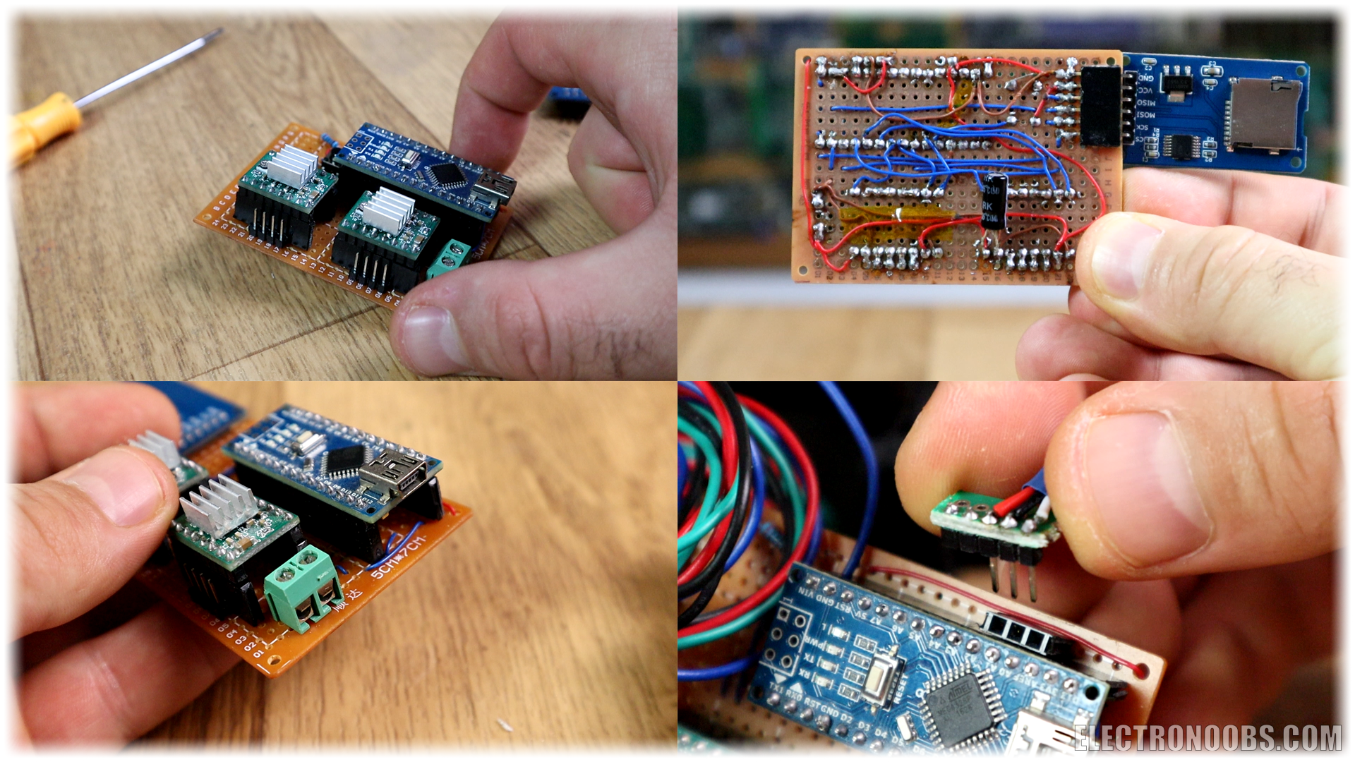
I've made all teh connections on a drilled PCB. We have the Arduino NANO with female pins so we could remove it. The SD card module on the side and the rest of the components. The input of 12V will eb connected to those two screw PCB connectors. I've used 0.1mm wire to make the connections. Remember to add those 47uF capacitors for the motor drivers. Connect the wires from the motors and sensor to the PCB. Make sure the rotation is in the desired direction. If not, juse reverse the motor inputs.
Let's see the code. Don't change anything in the code. Just the first variables at the beginning of the code acording to the parts you have used and the layer height you want. You have a code for the schematic using limit swithc for z-axis and for the manual homming. Download from below the code you want to use. If you don't have the limit switch connected, just use the other code.
/*ELECTRONOOBS 3D scanner using IR sensor SHARP GP2Y0A51SK0F;
  Datasheet GP2Y0A51SK0F: https://www.pololu.com/file/0J845/GP2Y0A41SK0F.pdf.pdf
  Tutorial: http://www.electronoobs.com/eng_arduino_tut30.php
  YouTube Channel: https://www.youtube.com/channel/UCjiVhIvGmRZixSzupD0sS9Q
  SUBSCRIBE!

  Schematic: http://www.electronoobs.com/eng_arduino_tut30_sch1.php
*/

#include <SPI.h>
#include <SD.h>

//Editable variables
int scan_amount = 40;                   //Amaunt of scans for each point. The result is the mean. This would increase the delay for each scan.
String file="scan_001.txt";             //Name of the saved file on the SD card
int z_axis_height = 12; //in cm         //Maximum height of the scaned file
int step_delay = 3000; //in us          //Delay for each step for the stepper motor in microseconds
float z_layer_height = 0.5; //in mm     //Layer height. The amount of mm for each layer.
int lead_screw_rotations_per_cm = 8;    //How many rotations needs the lead screw to make in order to make 1cm.
int steps_per_rotation_for_motor = 200; //Steps that the motor needs for a full rotation.
int distance_to_center = 8;             //In cm. Distance from sensor to the turntable center in cm

//I/O
int button = 2;
int limit_switch = 10;
//Turntable driver pins
int dir_r = 7;
int step_r = 8;
int enable_r = 9;
//Z-axis driver pins
int dir_z = 3;
int step_z = 5;
int enable_z = 6;

//Variables
File file_values;           //Used for the SD card module
int scan = 0;               //Activate/deactivate scanning
int scan_changed = 0;       //Scan process was changed
float distance = 0;         //Measured distance
float angle = 0;            //Rotation angle for each loop (0º-360º)
float x = 0;                //X, Y and Z coordinate
float y = 0;
float z = 0;
int z_loop = 0;             //variable used for the z-axis motor rotation
int r_loop = 0;             //variable used for the turntable motor rotation
float measured_analog = 0;  //Analog read from the distance sensor
float analog = 0;           //Analog MEAN
float RADIANS = 0.0;        //Angle in radians. We calculate this value later in Setup loop
int steps_z_height = 0;     //Variable used for the amount of steps in z-axis
int homed = 0;

void setup() {
  Serial.begin(9600);
  pinMode(A0, INPUT);
  pinMode(limit_switch, INPUT);
  pinMode(button, INPUT);
  analogReference(INTERNAL);
  SD.begin(4);
  pinMode(dir_z, OUTPUT);
  pinMode(step_z, OUTPUT);
  pinMode(enable_z, OUTPUT);
  pinMode(dir_r, OUTPUT);
  pinMode(step_r, OUTPUT);
  pinMode(enable_r, OUTPUT);
  digitalWrite(enable_z,HIGH);//disable the z_azis driver
  digitalWrite(enable_r,HIGH);//disable the z_azis driver


  //Calculate variables
  RADIANS = (3.141592 / 180.0) * (360/steps_per_rotation_for_motor);
  steps_z_height = (z_layer_height * steps_per_rotation_for_motor * lead_screw_rotations_per_cm)/10;


  while(!digitalRead(limit_switch) && homed == 0)
  {
    digitalWrite(enable_z,LOW);     //enable the z_azis driver
    digitalWrite(dir_z,HIGH);       //z_azis spin to left (lowering z-axis)
    digitalWrite(step_z,HIGH);      //z_azis make a step
    delayMicroseconds(step_delay);
    digitalWrite(step_z,LOW);
    delayMicroseconds(step_delay);
  }
  homed = 1;
}

void loop() {
//Wait till the push button is pressed
if(digitalRead(button))
{
  if(scan == 1 && scan_changed == 0)
  {
    scan=0;
    delay(3000);
    scan_changed=1;
  }
  if(scan == 0 && scan_changed == 0)
  {
    scan=1;
    delay(3000);
    scan_changed=1;
  }
  scan_changed = 0;
}


//If the scanning proces is ON
if(scan == 1)
{
  //We stop when we reach the maximum height
  if(z < z_axis_height)
  {
    for(int loop_cont = 0 ; loop_cont < steps_per_rotation_for_motor; loop_cont++)
    {
      getDistance();
      digitalWrite(enable_r,LOW);   //enable the turntable driver
      digitalWrite(dir_r,LOW);      //turntable spin to right
      digitalWrite(step_r,HIGH);    //make a step
      delayMicroseconds(step_delay);
      digitalWrite(step_r,LOW);
      delayMicroseconds(step_delay);
      angle = angle + RADIANS;      //Increase the angle by one more unit
      write_to_SD(x,y,z);           //Write x, y, z files to SD card function

      //Uncomment this for Serial debug
      /*
      Serial.print(loop_cont);     Serial.print("   ");
      Serial.print(angle);     Serial.print("   ");
      Serial.print(distance);     Serial.print("   ");
      Serial.print(x);     Serial.print("   ");
      Serial.print(y);     Serial.print("   ");
      Serial.print(z);     Serial.println("   "); */
    }
    angle = 0;  //Reset the angle value for next rotation

    /*My threaded rod needs 8 full rotations for 1cm. A full rotation is 200 steps in my case.
    We need 1600 for 1cm. So, we need 80 for 0.5mm. The amount is calulated automaically.
    Just change the variables at the beginning if you want*/
    while(z_loop < steps_z_height)
    {
    digitalWrite(enable_z,LOW);     //enable the z_azis driver
    digitalWrite(dir_z,LOW);        //z_azis spin to right
    digitalWrite(step_z,HIGH);      //z_azis make a step
    delayMicroseconds(step_delay);
    digitalWrite(step_z,LOW);
    delayMicroseconds(step_delay);
    z_loop = z_loop+1;              //Increase the loop by 1
    }
    z = z + z_layer_height;         //Increase the made z-height by 1 unit
    z_loop = 0;                     //Reset the z-axis rotation variable

}//end of if z_height

//We finished the scan, we stop the drivers
else
{
  digitalWrite(enable_z,HIGH);
  digitalWrite(enable_r,HIGH);
}

}//if scan
}//End ov void loop


//Function that gets the distance from sensor
double getDistance()
{
  for (int aa=0; aa < scan_amount; aa++)
  {
    measured_analog= analogRead(A0);
    delay(2);
    analog = analog + measured_analog;
  }
  distance = analog/scan_amount;        //Get the mean. Divide the scan by the amount of scans.
  analog=0;//reset the andlog read total value
  measured_analog = 0; //reset the andlog read value
  distance = mapFloat(distance,0.0,1023.0,0.0,3.3); //Convert analog pin reading to voltage
  distance = -5.40274*pow(distance,3)+28.4823*pow(distance,2)-49.7115*distance+31.3444; //From datasheet
  distance = distance_to_center - distance;  //the distance d = distance from sensor to center - measured distance
  y =  (cos(angle) * distance);
  x =  (sin(angle) * distance);

  /*//For debug
   * Serial.print(distance); Serial.print("   ");
  Serial.print(x); Serial.print("   ");
  Serial.print(y); Serial.print("   ");
  Serial.print(z); Serial.print("   ");
  Serial.print(angle); Serial.println("   "); */
}


//Function that maps the value in a float format
float mapFloat(float fval, float val_in_min, float val_in_max, float val_out_min, float val_out_max)
{
  return (fval - val_in_min) * (val_out_max - val_out_min) / (val_in_max - val_in_min) + val_out_min;
}


//Function that writes the value to the SD card
void write_to_SD(float SDx, float SDy, float SDz)
{
  file_values = SD.open(file, FILE_WRITE);
  if (file_values)
  {
    file_values.print(SDx); file_values.print(",");
    file_values.print(SDy); file_values.print(",");
    file_values.println(SDz);
    file_values.close();
  }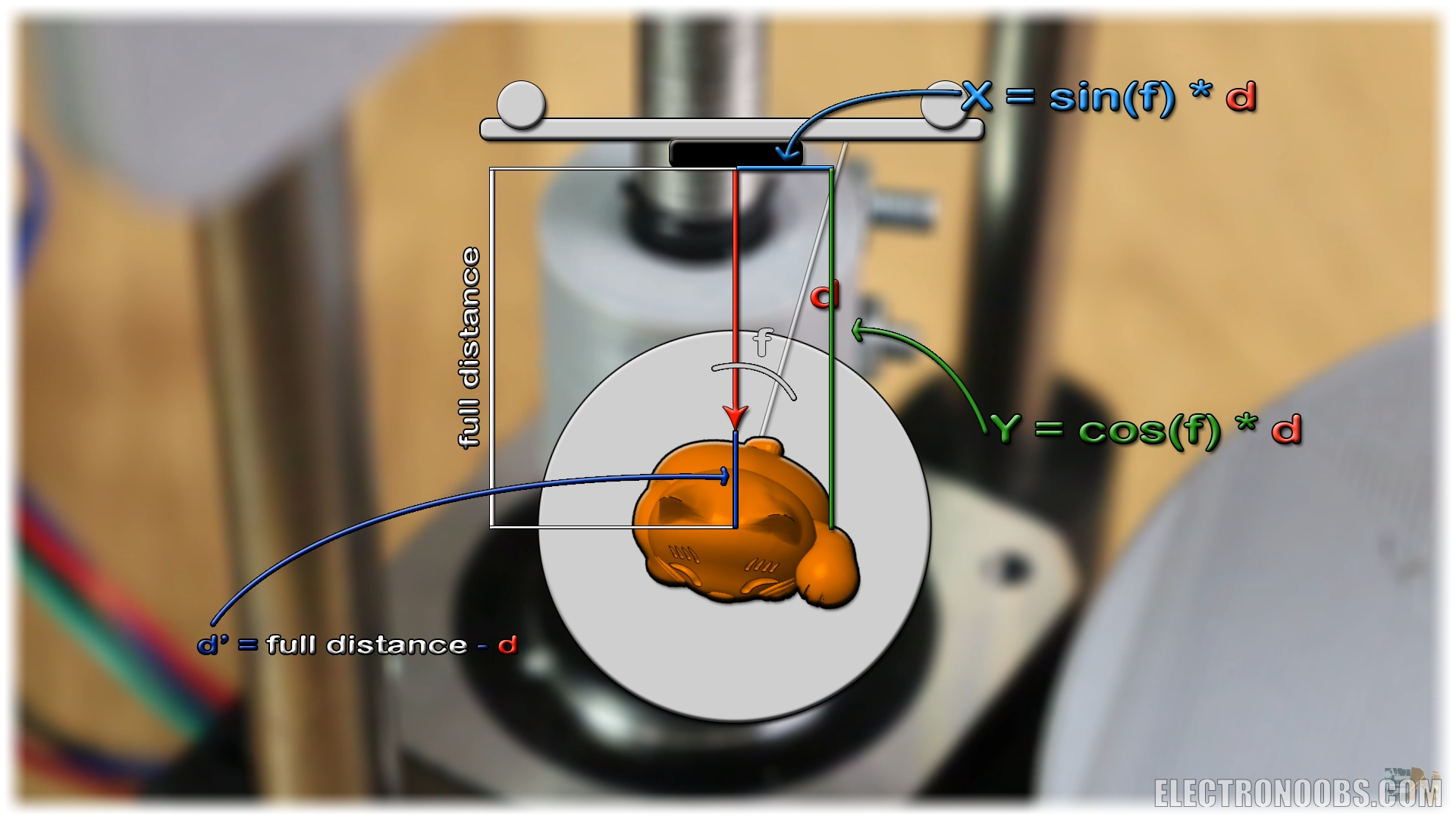
}Read all the comments in the code for better understanding. The code is simple. Create a loop that will make 360º rotation of the turntable. Each step we measure the distance. The X and Y increment is given by simple trigonommetry as seen below. Next, the x, y and z variable are stored to the SD card divided by a "," character. This step is important for later.
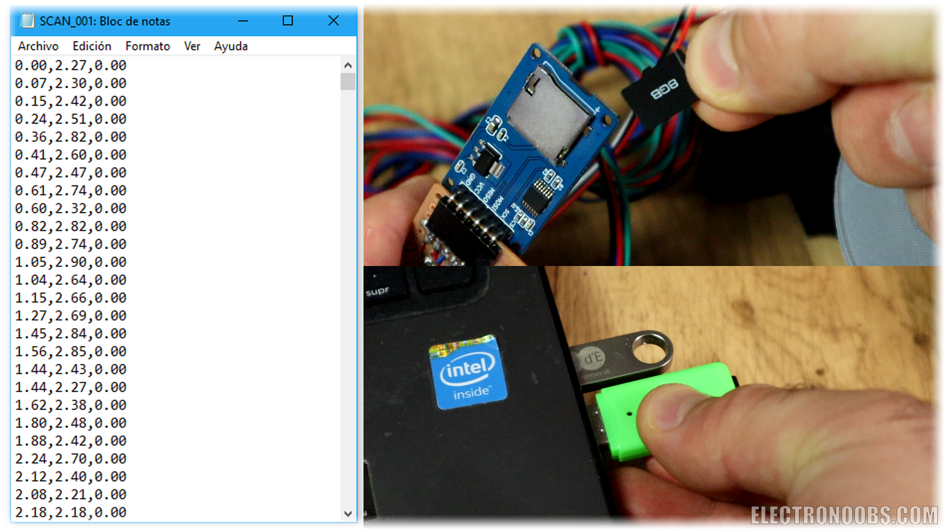
Place the object on the turntable in the middle. Connect power supply and wait for theamchine to home itself. When reached, press the scanning push button and wait. Depending on the layer height you choose and object size it will take more or less to complete. Once complete, remove the SD card.
Remove the SD card and copy the file to your PC. The file should have the next format. Three columns separated by a comma with the values of the x, y,and z coordinates. This are just points in a format of a point cloud. To obtain an STL file, we use the MESHLAB software which you could download from a link below.
Use MESHLAB
Downlad and install MESHLAB with the default install. Open meshlab and go to file, inport mesh. Here open the scanned file. In the next window select XYZ format and as a separator select the comme ','. Now the point cloud is open. We haev to give normals to the points. For that go to filter, normal curvature and orientation, compute normal for point set and in this window play with the settings. 10 was a good number. Click apply and close the window.
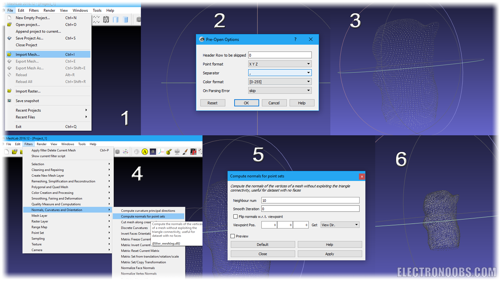
Now go to filter, remeshing simplification and reconstruction and here select screened poisson surface reconstruction. Play with the settings if you want and then click apply. Close the window and there we have our file.
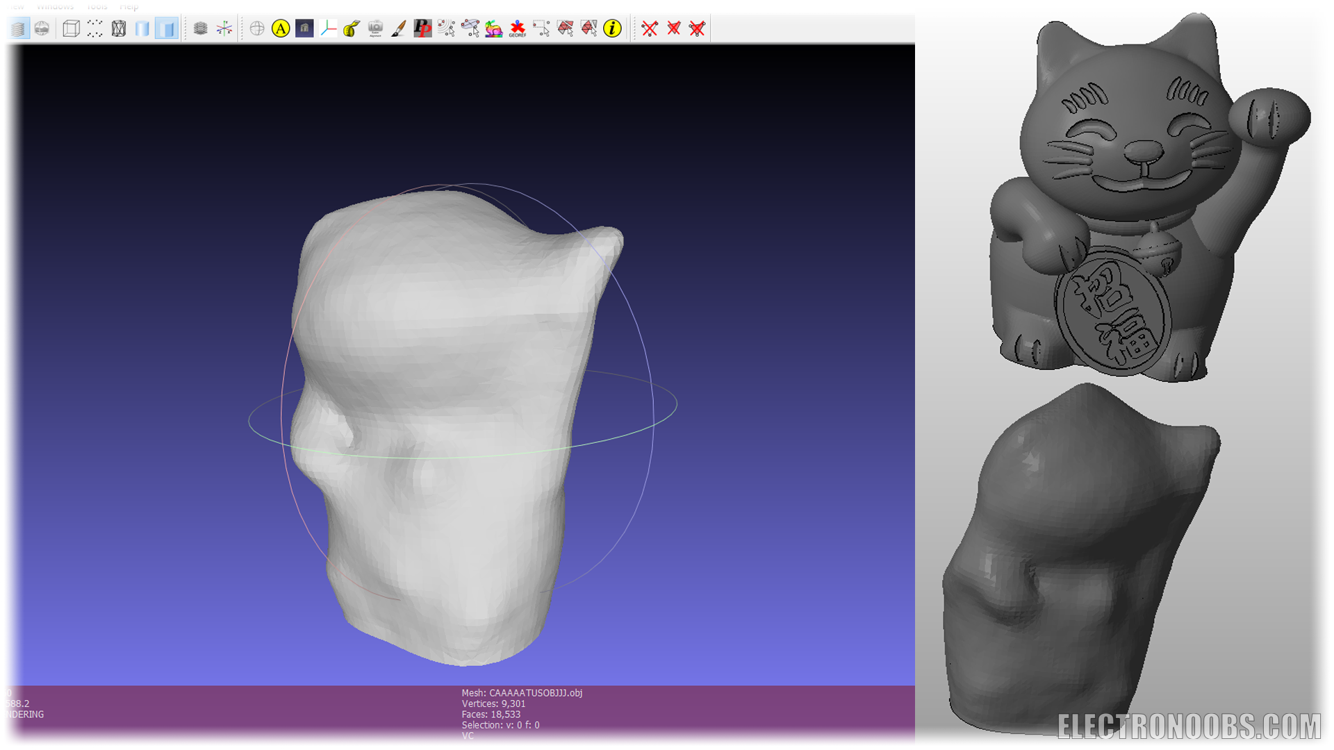
ow, the file was scanned. The precision is not that good. For learning purposes, this project is more than enough.
So, there you have it guys. The precision could get better using a better distance sensor. Maybe a laser based one would give better precision. Also have in mind that in the code, the sensor makes 40 measurements and give the mean of those in order to increase precision. Consider using a lead screw instead of a normal threaded rod, better sensor, more measurements, add an end stop switch and improve this project however you want. Help me on PATREON.
Comments


Leave a comment
Please login in order to comment.