Welcome back. Today we will build a power meter using Arduino. We already build the current meter in a past tutorial and also a capacitance and resistance meter and the inductance meter. Check all those tutorials here and learn more. Now, power is voltage times current, so using the same model as in the current meter, we will build today a power meter. I want it to display the voltage, current and power. This would be a very useful tool while wor
by: ELECTRONOOBS on 2026-06-18
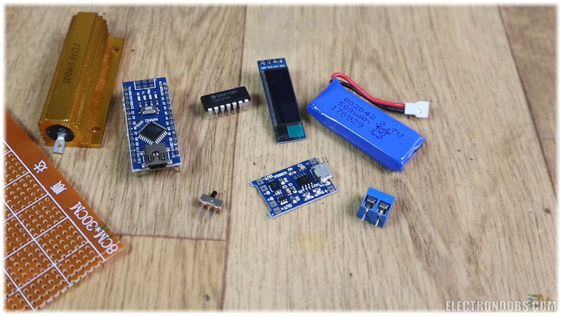
1 x Arduino NANO/UNO LINK eBay
1 x i2c OLED: LINK eBay
1 x Shunt 0.01: LINK eBay
1 x LM324: LINK eBay
1 x battery charger: LINK eBay
1 x sliding switch: LINK eBay
1 x 4.7 LIPO: LINK eBay
1 x PCB connectors: LINK eBay
Resistors: LINK eBay
Wires LINK eBay
Female PCB pins LINK eBay
Male PCB pins LINK eBay
Drilled PCB LINK eBay
Wire, soldering iron, solder, etc...
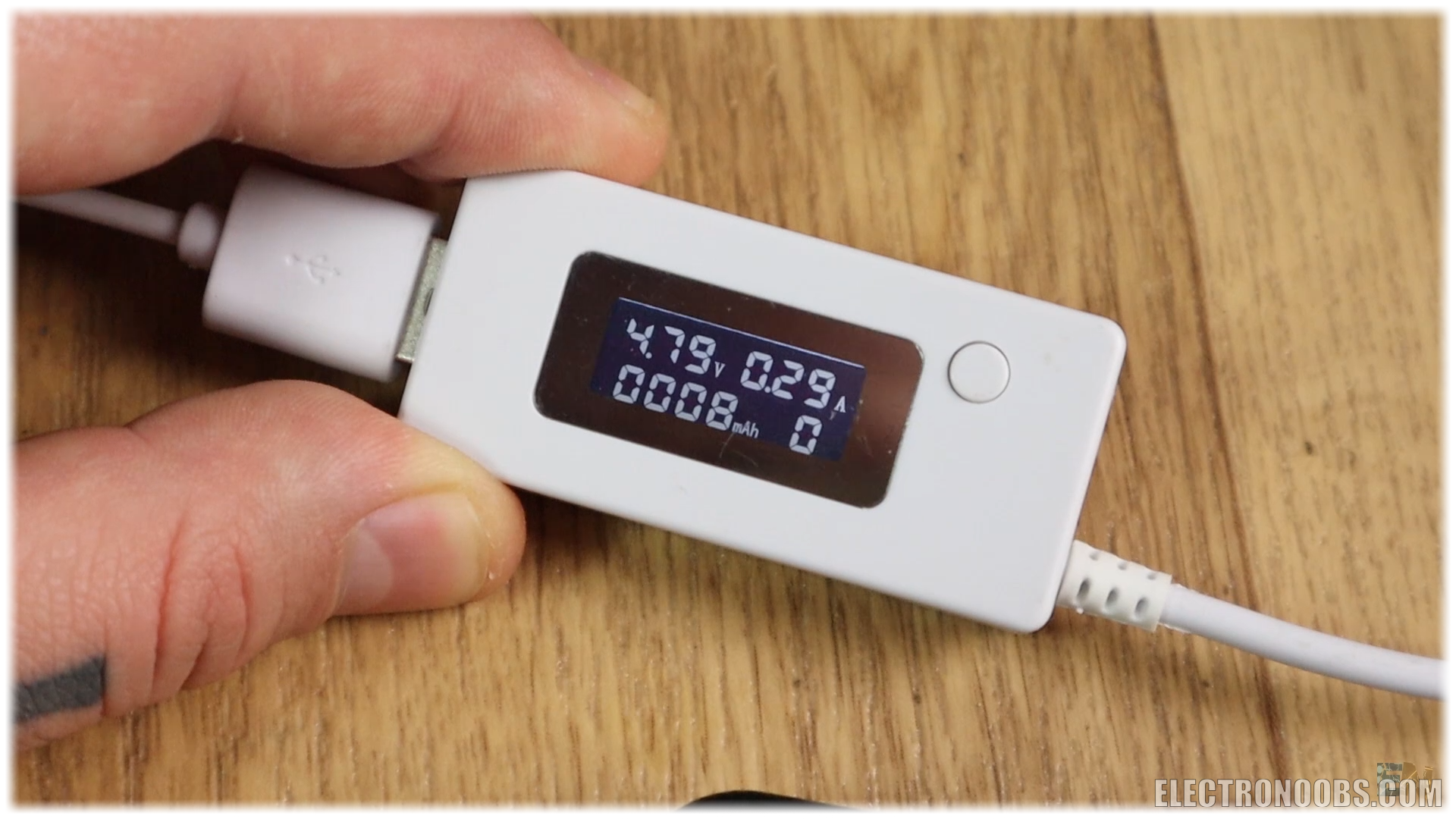
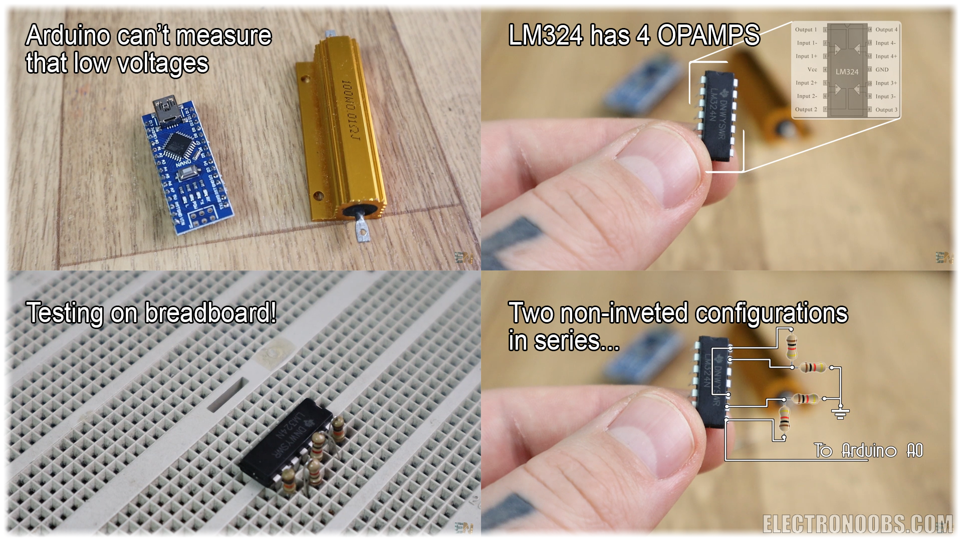
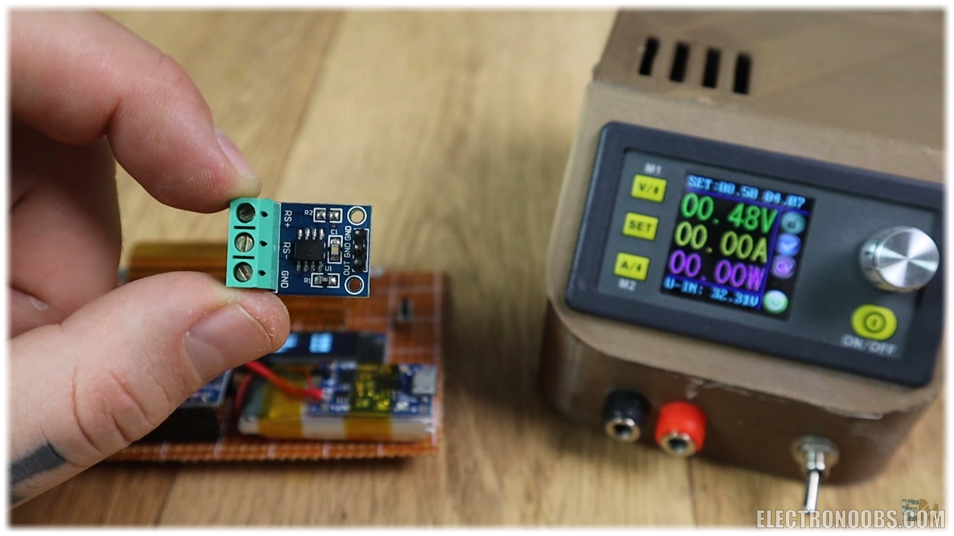
So, I bought this power meter below from eBay and as you can see, once plugged to an USB and then to a device, it shows the power that goes to that device. But let’s build our homemade power meter. So, for our project the first thing is there to do is measure current. I will use the Arduino NANO for this project. But the Arduino can’t measure current only voltage with and ADC. But we know that the current is the voltage divided by resistance.
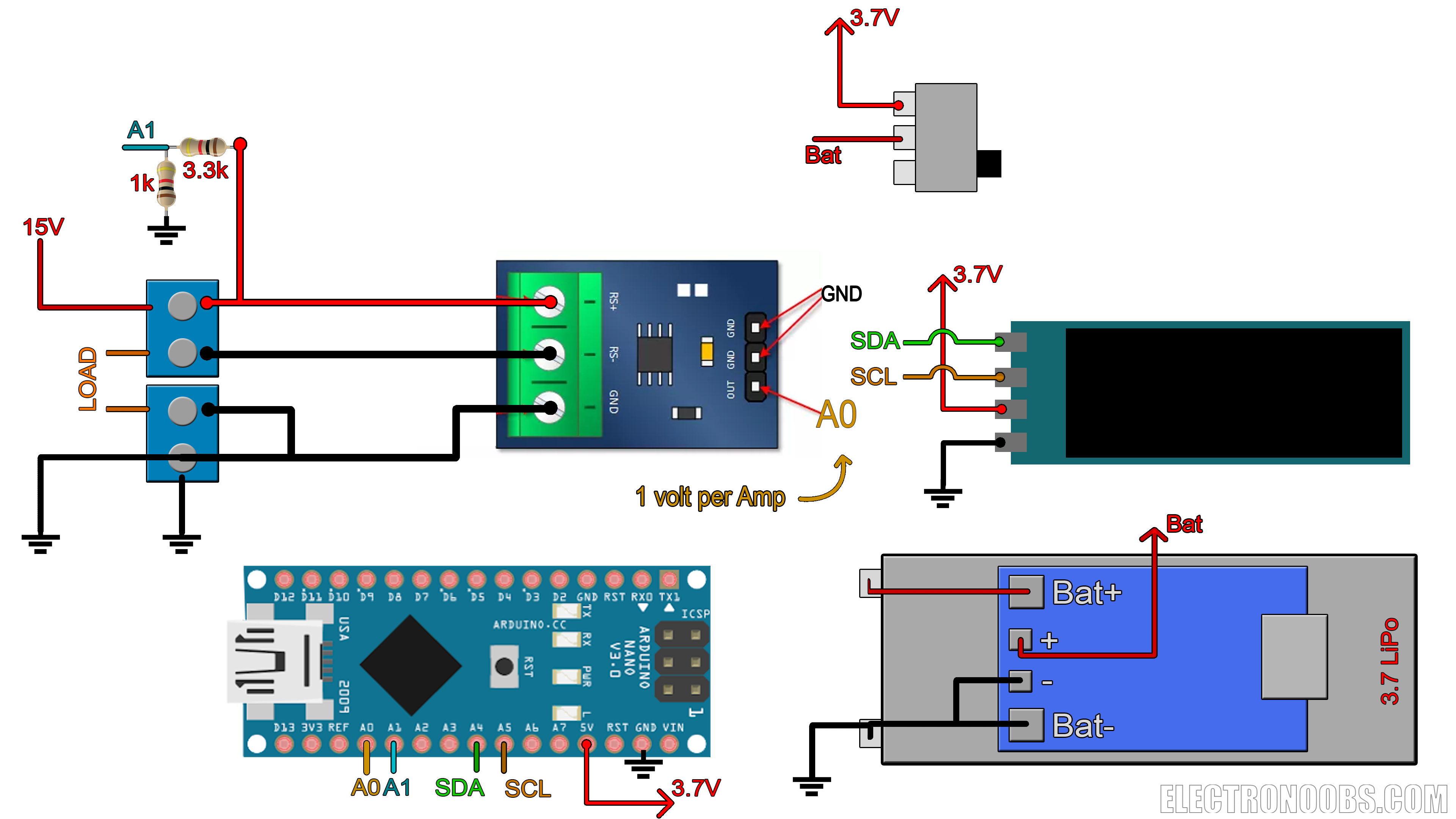
So, for that, let’s imagine this setup. This below will be our LOAD on which we want to measure current, let’s say it is a light bulb. In series with that load, we add a resistance which value we know (0.01 in this case). That is a very important step in this tutorial, we really have to know the value of this resistor. If we measure the voltage drop on this resistor, we can easily measure the current. How? Well, we know the resistance value. We divide the measured voltage by that resistance and we get the current. It is basic ohm law.
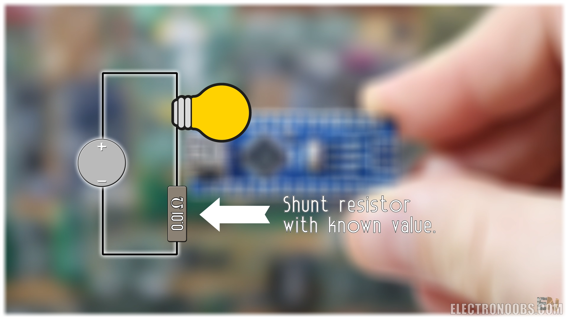
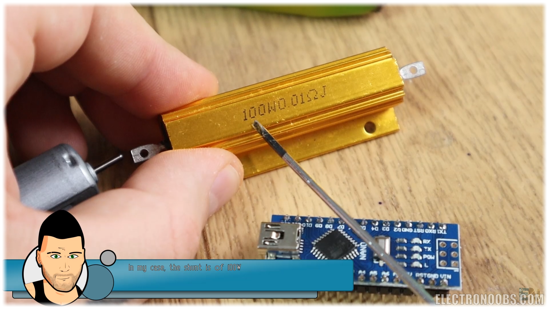
Only one thing. This resistance has to be very, very, low. Otherwise it would create a voltage droop big enough to affect the voltage on the load, and we don’t want that. For example, if you want to apply 5 volts to the load and there is a voltage drop of 2 volts on the resistor, you will only apply 3 volts to that load and you won’t want that. For that, I’ll use a 0.01 ohms resistor like this one below. Choose one that could withstand over 10W or 15W of power, so you could measure up to 1 amp at 12V.
Now we are facing a different problem. With a resistor this low (0.01), the voltage drop on that resistor will be very, very, low and the Arduino couldn’t measure it. So, for that, we amplify the voltage drop with an OpAmp. We control the gain of the OpAmp by knowing the amplifying resistors values, so later in the code we can easily calculate the exact amount of current. I’ll use the LM324 OpAmp. Since it has 4 integrated amplifiers, I’ll use two of them in series, each with a gain of 11. I’ll use non-inverted configuration with resistors of 10K and 1K for the gain. Using the output formula of this configuration, that will give me a gain of 11 for each stage and a total gain of 121. Measure the exact values of the resistors for better precision of the gain later in the code. The output from the OpAmps will be connected to analog input A0 of the Arduino and by that we could measure current.
But, we also need to measure voltage. Since I want this to work up to 15V I’ll use a voltage divider that could lower that value to under 3.7V for The Arduino and connect that to analog input A1. If you want a higher voltage range, make sure you change the voltage divider value.
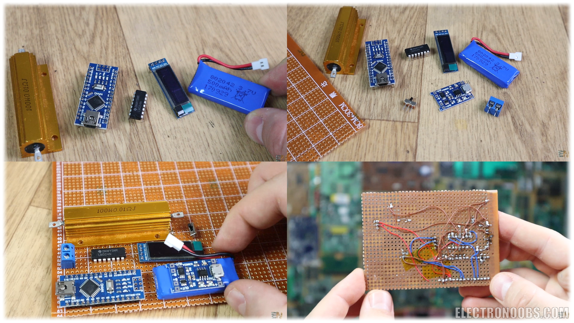
Ok so, I’ll use an i2c OLED display to print the power, current and voltage values. To supply the circuit, I’ll use a Lipo battery of 3.7 volts and with a USB battery charger connected to it. We will also need a sliding switch to power on and off the board, some PCB connectors and a drilled PCB.
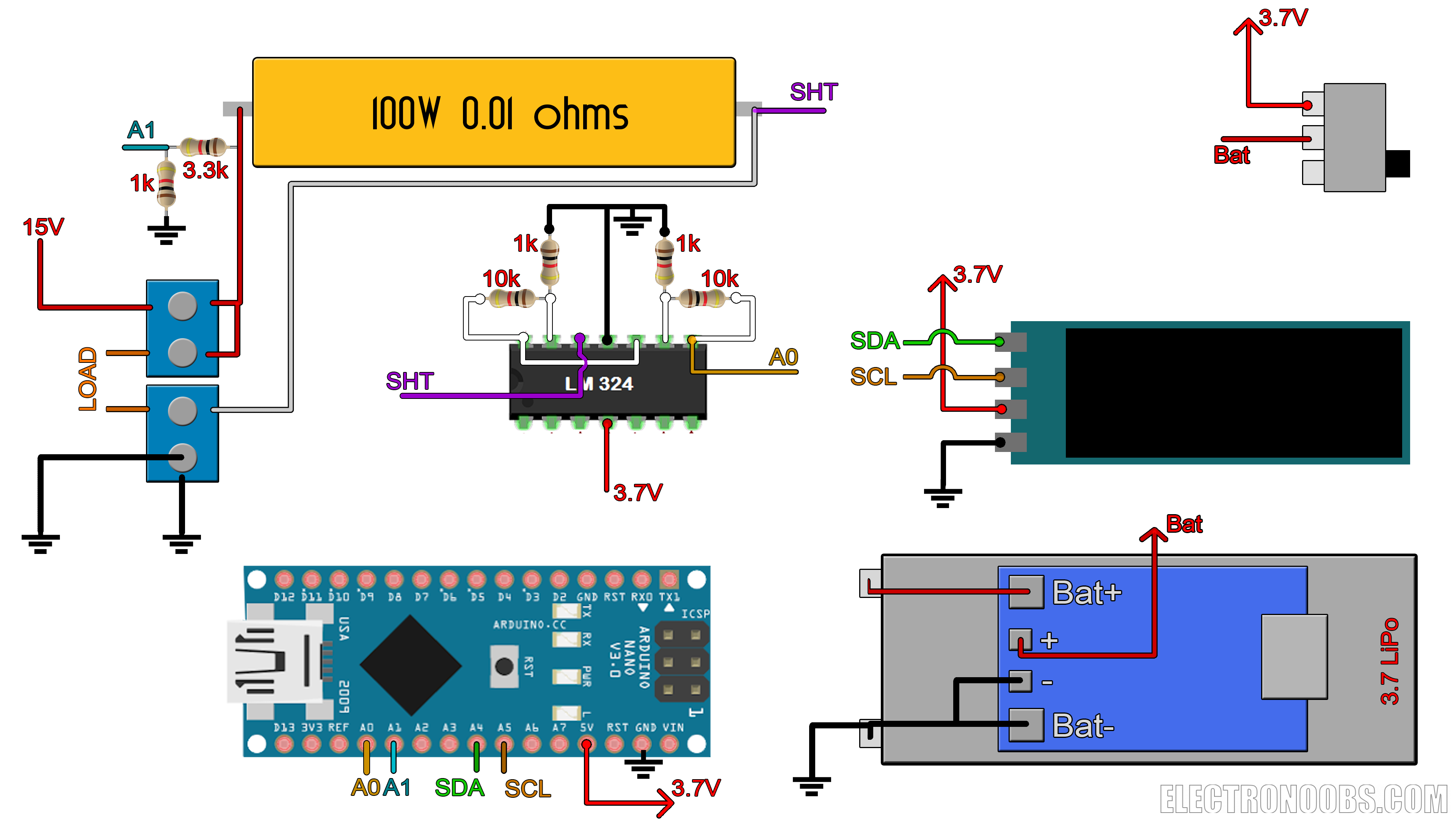
This is the schematic for the project. Download it from a link below and have it in front of you while soldering.
I gather all the components for the project and start soldering. I first decide where to place each component. Once all the components are soldered, I’ve used thin wire for the connections. Now the board is done, so let’s program it.
Download the code from a link below and open it in your Arduino IDE. First of all, make sure you have the OLED Adafruit_GFX library and Adafruit SSD1306 for this i2c display. If not, download the zip files below, go to sketch, include library, add .zip library and select the downloaded files.
Now, read all the comments in the code to understand more. But the general idea goes like this. We measure the voltage drop and divide it by the OpAmp gain. Now this is the real voltage drop on the shunt resistor. We divide that by the resistance, in this case 0.01 ohms and we get the current. At the same time, another analog input is connected to that voltage divider. We measure the voltage drop and multiply that by the voltage divider value in order to obtain the real voltage.
/*********************************************************************
Power meter example. Author: ELECTRONOOBS. 08/05/2018
Tutorial video: https://www.youtube.com/watch?v=_PKQdEUam6Y
Tutorial link: http://www.electronoobs.com/eng_arduino_tut28.php
*********************************************************************/


//Inport the libraries
#include <SPI.h>
#include <Wire.h>
#include <Adafruit_GFX.h>
#include <Adafruit_SSD1306.h>

#define OLED_RESET 4
Adafruit_SSD1306 display(OLED_RESET);

#define NUMFLAKES 10
#define XPOS 0
#define YPOS 1
#define DELTAY 2


#if (SSD1306_LCDHEIGHT != 32)
#error("Height incorrect, please fix Adafruit_SSD1306.h!");
#endif


//variables
float voltage = 0;
float current_voltage = 0;          //this maps the measured voltage in volts from 0 t 3.7V
float current =  0;
float power=0;
float voltage_compenstion = 0;
float energy = 0;
unsigned long previousMillis = 0;
unsigned long loop_delay = 100;
unsigned long Time = 0;

void setup()   {
  //Begin the display i2c omunication
  display.begin(SSD1306_SWITCHCAPVCC, 0x3C);  // initialize with the I2C addr 0x3C (for the 128x32)
}


//THIS FUNCTION WILL MAP THE float VALUES IN THE GIVEN RANGE
float fmap(float x, float in_min, float in_max, float out_min, float out_max) {
  return (x - in_min) * (out_max - out_min) / (in_max - in_min) + out_min;
}

//This functions will calculate the curret, voltage, power and energy values
void get_values()
{
  voltage = (fmap(analogRead(A1),0.0,1023.0,0.0,3.7)) / 0.218;

  voltage_compenstion = fmap(voltage,0.99,   14.01  ,0.02,   0.38) ;
  /*Ok, this vompensation is for the non linear voltage amplification.
   * This is what I've done. Ive measured the voltage at 0.99V input and 14.01V input.
   * At 1V input I had an error of 0.02 and at 14.01 of 0.38. I maap that value to that range
   * and add the linear compensation
  */

  voltage = voltage + voltage_compenstion;

  //This maps the measured voltage in volts from 0 t 3.7V
  current = (fabs(fmap(analogRead(A0), 0.0, 1023.0, 0.0, 3.7)))/1.21;
/* Pay atention.
 *        - We read the value on A0 wich is ihe input from the amplifiers.
 *        - We map the digital values from range 0-1023 to range 0-3.7V since we are using 3.7V battery.
 *          this value won't change with the battery voltage since the analog read is related to the Vref
 *        - We divide by 121 (OpAmp gain) and then by 0.01 (shunt resistance). All in one, we divide
 *        bu 1.21 and that is the current value. HERE YOU SHOULD CHANGE THE 1.21 value in order to have
 *        same current values as on yur power supply.*/

  power = voltage*current;              //Calculate power and energy
  energy = energy + (power/3600)/1000;
}


void loop() {
  unsigned long currentMillis = millis();
  if (currentMillis - previousMillis >= loop_delay)
  {
    previousMillis = currentMillis;
    get_values();
    Time = currentMillis / 1000;        //Get the elapsed time in seconds

    //Print all the values on the display
    display.clearDisplay();
    display.setTextSize(1);
    display.setTextColor(WHITE);
    display.setCursor(0,0);
    display.print(voltage);
    display.print("V");

    display.setCursor(60,0);
    display.print(current);
    display.print("A");

    display.setCursor(0,11);
    display.print(power);
    display.print("W");

    display.setCursor(60,11);
    display.print(energy);
    display.print("mWh");

    display.setCursor(100,22);
    display.print(Time);
    display.print("s");

    display.display();    //This functions will display the data
  }
}We print the current and power value on the display and is time to test the code. I upload the code to the Arduino. I slide the switch and power the board. The display starts and it prints the current, voltage and power. Now I connect a load of 15ohms to the board and connect the input to my power supply and apply a 10V input. And there you go. I've got the current and power values on my power meter and the values are pretty decent as you can see below.
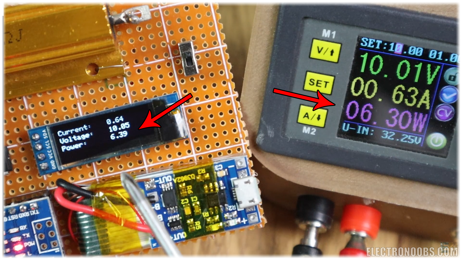
But this is after calibrating the code. You see, all the values we have used, the resistors, the amplifier gain, the analog inputs, are not perfect. Just upload the code to the board and if the values are not the same as on your power supply, go in the code, read these comments below and change the values according to your resistors, gain, and shunt resistor value.
//This maps the measured voltage in volts from 0 t 3.7V
  current = (fabs(fmap(analogRead(A0), 0.0, 1023.0, 0.0, 3.7)))/1.21;
/* Pay atention.
 *        - We read the value on A0 wich is ihe input from the amplifiers.
 *        - We map the digital values from range 0-1023 to range 0-3.7V since we are using 3.7V battery.
 *          this value won't change with the battery voltage since the analog read is related to the Vref
 *        - We divide by 121 (OpAmp gain) and then by 0.01 (shunt resistance). All in one, we divide
 *        bu 1.21 and that is the current value. HERE YOU SHOULD CHANGE THE 1.21 value in order to have
* same current values as on yur power supply.*/For example. I set my supply at 5V. With a load of around 15ohms, there is a current passing of 0.31 amps. That would create a voltage drop on the shunt of 0.31 multiplied by 0.01 equal to 3.1mV. I measure that with my multimeter and indeed. There is a 3.1mV drop. With a gain of 121 the amplifiers output should be around of 0.37 volts. Let’s check that. Well, it is 0.42 because the gain is not perfect. So now I go in the code, follow those steps here and adjust the gain.
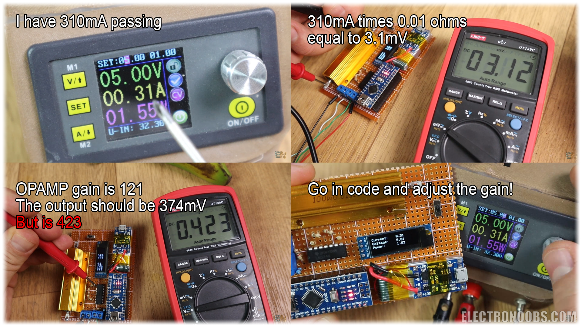
So, as a quick resume, this is what we do. Measure the voltage drop on the shunt resistor and on the main input. Amplify the voltage on the shunt with the OPAMP two times and then read it with Arduino. Calculate the current by dividing the voltage by 0.01 ohms and multiply current by main input voltage and get the Power. That's it.
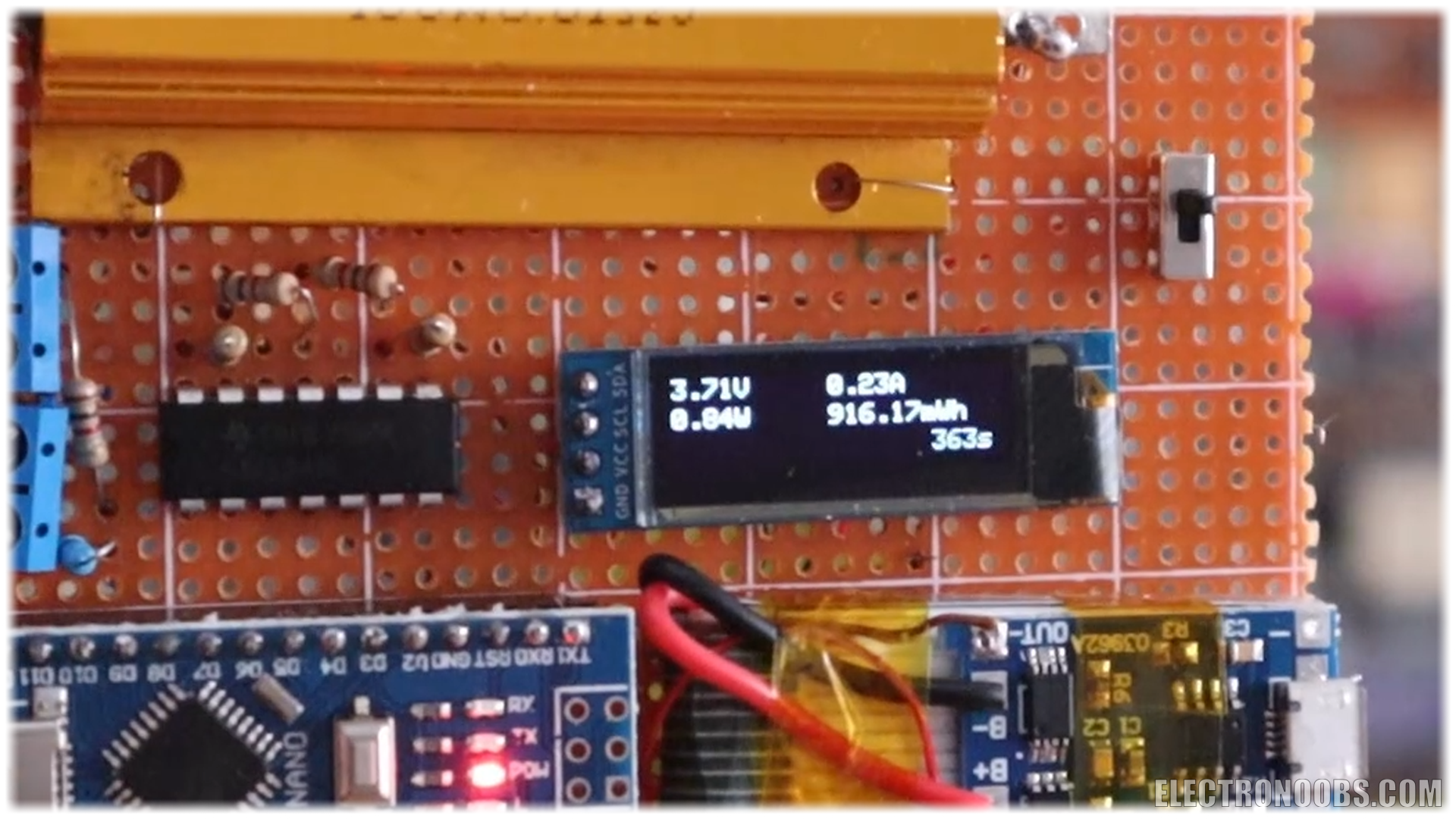
I print on the screen the 3 values, power, voltage and current. And our project is done. The final code also prints the m watts hour and the elapsed time since the board was power as you can see below.
If you don’t want to use a huge shunt resistor like the one before, you could make one yourself but probably not that accurate. For example, I’ve used a thick copper wire and made some sort of small coil with it. Now, I plug it into my power supply and apply 0.5 Voltage.
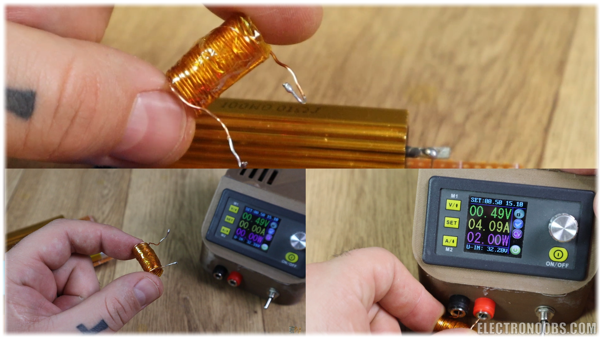
In my case, with 0.48 volts and 4 amps of current gives me a resistance of 0.12 ohms which would work for low values of current. So basically, you could make your own crude shunt resistor and probably not give it a coil shape, that would be better.
The resistance that we have measured is not precise, but once again, once the code and the board is done, you could test it using another meter, and adjust the code so you get same values.
Below, you will also find the schematic and codes for the same project but using the current meter module. This module will sense the current without the huge shunt resistor and the extra OpAmp circuit so that will make the project smaller and probably easier. So, check the links below for all the extra schematics and codes. Use any USB charger to charge the battery. Be careful, the boar input has polarity. The load in the middle, and positive on one side and ground on the other, otherwise the board won’t work.
/*********************************************************************
Power meter example. Author: ELECTRONOOBS. 08/05/2018
Tutorial video: https://www.youtube.com/watch?v=_PKQdEUam6Y
Tutorial link: http://www.electronoobs.com/eng_arduino_tut28.php
*********************************************************************/


//Inport the libraries
#include <SPI.h>
#include <Wire.h>
#include <Adafruit_GFX.h>
#include <Adafruit_SSD1306.h>

#define OLED_RESET 4
Adafruit_SSD1306 display(OLED_RESET);

#define NUMFLAKES 10
#define XPOS 0
#define YPOS 1
#define DELTAY 2


#if (SSD1306_LCDHEIGHT != 32)
#error("Height incorrect, please fix Adafruit_SSD1306.h!");
#endif


//variables
float voltage = 0;
float current_voltage = 0;          //this maps the measured voltage in volts from 0 t 3.7V
float current =  0;
float power=0;
float voltage_compenstion = 0;
float energy = 0;
int RawValue= 0;

unsigned long previousMillis = 0;
unsigned long loop_delay = 100;
unsigned long Time = 0;

void setup()   {
  //Begin the display i2c omunication
  display.begin(SSD1306_SWITCHCAPVCC, 0x3C);  // initialize with the I2C addr 0x3C (for the 128x32)
}


//THIS FUNCTION WILL MAP THE float VALUES IN THE GIVEN RANGE
float fmap(float x, float in_min, float in_max, float out_min, float out_max) {
  return (x - in_min) * (out_max - out_min) / (in_max - in_min) + out_min;
}

//This functions will calculate the curret, voltage, power and energy values
void get_values()
{
  voltage = (fmap(analogRead(A1),0.0,1023.0,0.0,3.7)) / 0.218;
  //The module gives one volt per Amp.
  RawValue = analogRead(A0);
  current = (RawValue * 5.0 )/ 1024.0; // scale the ADC, we get current value in Amps

  power = voltage*current;              //Calculate power and energy
  energy = energy + (power/3600)/1000;
}


void loop() {
  unsigned long currentMillis = millis();
  if (currentMillis - previousMillis >= loop_delay)
  {
    previousMillis = currentMillis;
    get_values();
    Time = currentMillis / 1000;        //Get the elapsed time in seconds

    //Print all the values on the display
    display.clearDisplay();
    display.setTextSize(1);
    display.setTextColor(WHITE);
    display.setCursor(0,0);
    display.print(voltage);
    display.print("V");

    display.setCursor(60,0);
    display.print(current);
    display.print("A");

    display.setCursor(0,11);
    display.print(power);
    display.print("W");

    display.setCursor(60,11);
    display.print(energy);
    display.print("mWh");

    display.setCursor(100,22);
    display.print(Time);
    display.print("s");

    display.display();    //This functions will display the data
  }
}Ok guys, so this is my power meter board. Kind of the same as in the current meter project. I hope that you like it and learn something new. If you would like to support this kind of projects, check my Patreon page. I would appreciate that guys. Now you know how to build a multimeter with Arduino because we have seen the resistance meter, also measured capacitance and finally inductance and current. A frequency meter would be very easy, so that means that this will be the last meter of this video series.
Comments


Leave a comment
Please login in order to comment.