This code is for the schematic.
/*********************************************************************
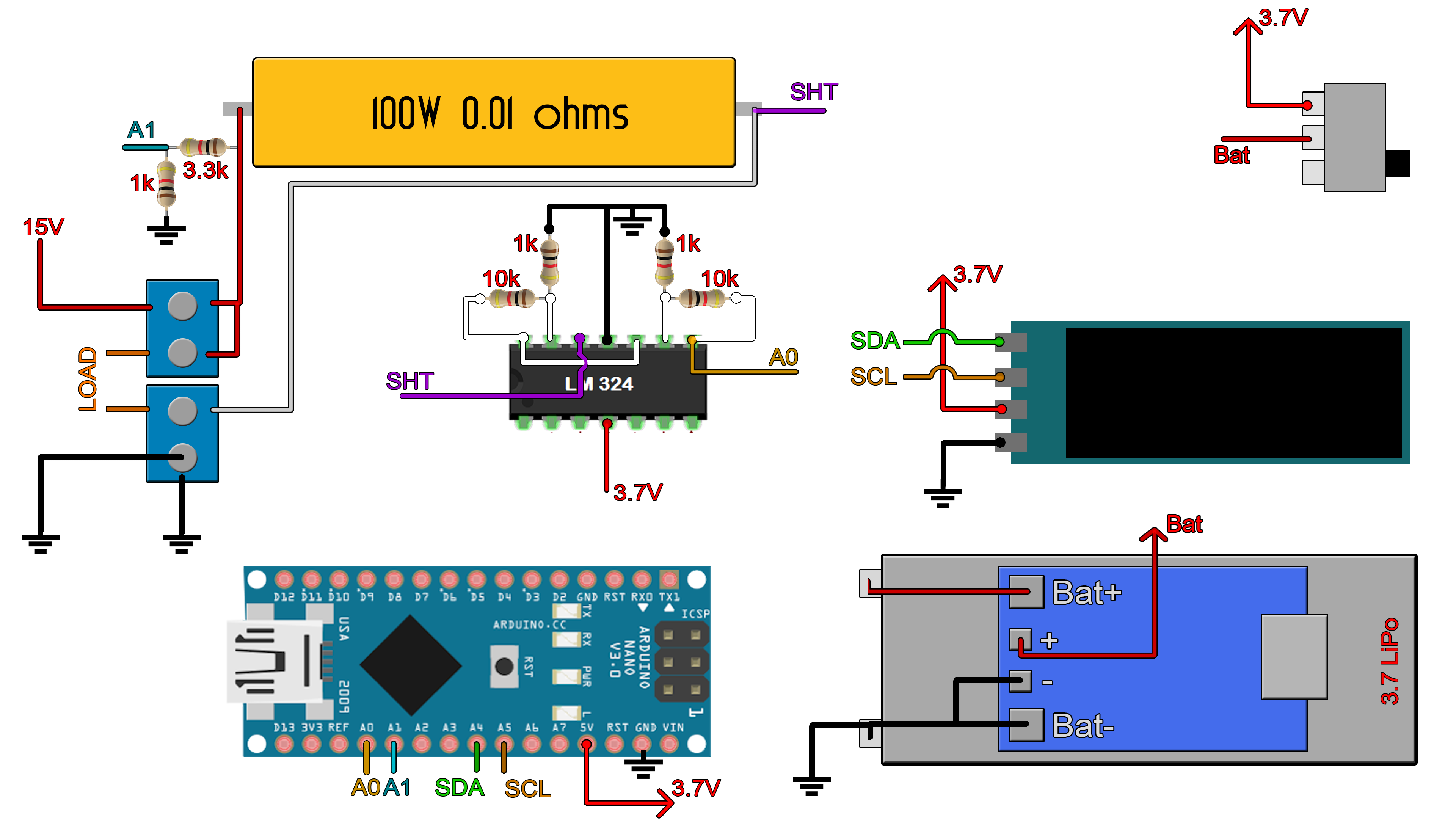
Power meter example. Author: ELECTRONOOBS. 08/05/2018
Tutorial video: https://www.youtube.com/watch?v=_PKQdEUam6Y
Tutorial link: http://www.electronoobs.com/eng_arduino_tut28.php
*********************************************************************/
//Inport the libraries
#include <SPI.h>
#include <Wire.h>
#include <Adafruit_GFX.h>
#include <Adafruit_SSD1306.h>
#define OLED_RESET 4
Adafruit_SSD1306 display(OLED_RESET);
#define NUMFLAKES 10
#define XPOS 0
#define YPOS 1
#define DELTAY 2
#if (SSD1306_LCDHEIGHT != 32)
#error("Height incorrect, please fix Adafruit_SSD1306.h!");
#endif
//variables
float voltage = 0;
float current_voltage = 0; //this maps the measured voltage in volts from 0 t 3.7V
float current = 0;
float power=0;
float voltage_compenstion = 0;
float energy = 0;
unsigned long previousMillis = 0;
unsigned long loop_delay = 100;
unsigned long Time = 0;
void setup() {
//Begin the display i2c omunication
display.begin(SSD1306_SWITCHCAPVCC, 0x3C); // initialize with the I2C addr 0x3C (for the 128x32)
}
//THIS FUNCTION WILL MAP THE float VALUES IN THE GIVEN RANGE
float fmap(float x, float in_min, float in_max, float out_min, float out_max) {
return (x - in_min) * (out_max - out_min) / (in_max - in_min) + out_min;
}
//This functions will calculate the curret, voltage, power and energy values
void get_values()
{
voltage = (fmap(analogRead(A1),0.0,1023.0,0.0,3.7)) / 0.218;
voltage_compenstion = fmap(voltage,0.99, 14.01 ,0.02, 0.38) ;
/*Ok, this vompensation is for the non linear voltage amplification.
* This is what I've done. Ive measured the voltage at 0.99V input and 14.01V input.
* At 1V input I had an error of 0.02 and at 14.01 of 0.38. I maap that value to that range
* and add the linear compensation
*/
voltage = voltage + voltage_compenstion;
//This maps the measured voltage in volts from 0 t 3.7V
current = (fabs(fmap(analogRead(A0), 0.0, 1023.0, 0.0, 3.7)))/1.21;
/* Pay atention.
* - We read the value on A0 wich is ihe input from the amplifiers.
* - We map the digital values from range 0-1023 to range 0-3.7V since we are using 3.7V battery.
* this value won't change with the battery voltage since the analog read is related to the Vref
* - We divide by 121 (OpAmp gain) and then by 0.01 (shunt resistance). All in one, we divide
* bu 1.21 and that is the current value. HERE YOU SHOULD CHANGE THE 1.21 value in order to have
* same current values as on yur power supply.*/
power = voltage*current; //Calculate power and energy
energy = energy + (power/3600)/1000;
}
void loop() {
unsigned long currentMillis = millis();
if (currentMillis - previousMillis >= loop_delay)
{
previousMillis = currentMillis;
get_values();
Time = currentMillis / 1000; //Get the elapsed time in seconds
//Print all the values on the display
display.clearDisplay();
display.setTextSize(1);
display.setTextColor(WHITE);
display.setCursor(0,0);
display.print(voltage);
display.print("V");
display.setCursor(60,0);
display.print(current);
display.print("A");
display.setCursor(0,11);
display.print(power);
display.print("W");
display.setCursor(60,11);
display.print(energy);
display.print("mWh");
display.setCursor(100,22);
display.print(Time);
display.print("s");
display.display(); //This functions will display the data
}
}