


If you don’t want to use a huge shunt resistor like the one before, you could make one yourself but probably not that accurate. For example, I’ve used a thick copper wire and made some sort of small coil with it. Now, I plug it into my power supply and apply 0.5 Voltage.
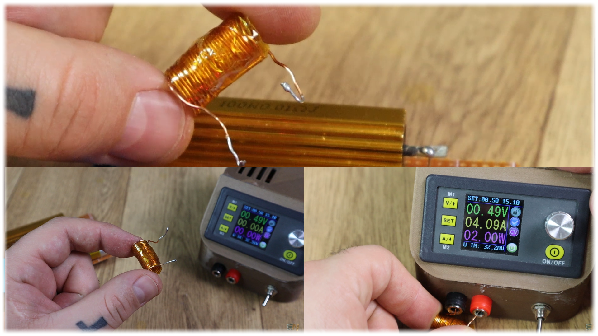
In my case, with 0.48 volts and 4 amps of current gives me a resistance of 0.12 ohms which would work for low values of current. So basically, you could make your own crude shunt resistor and probably not give it a coil shape, that would be better.
The resistance that we have measured is not precise, but once again, once the code and the board is done, you could test it using another meter, and adjust the code so you get same values.
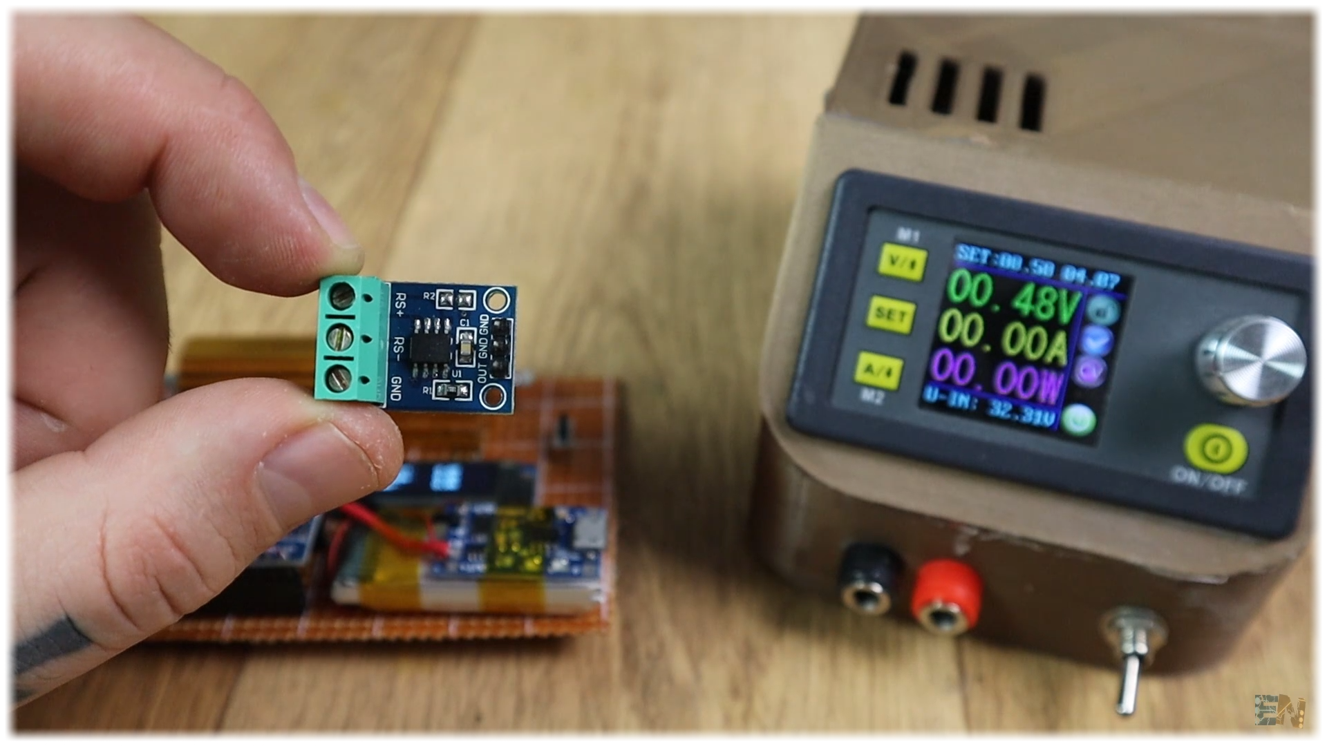
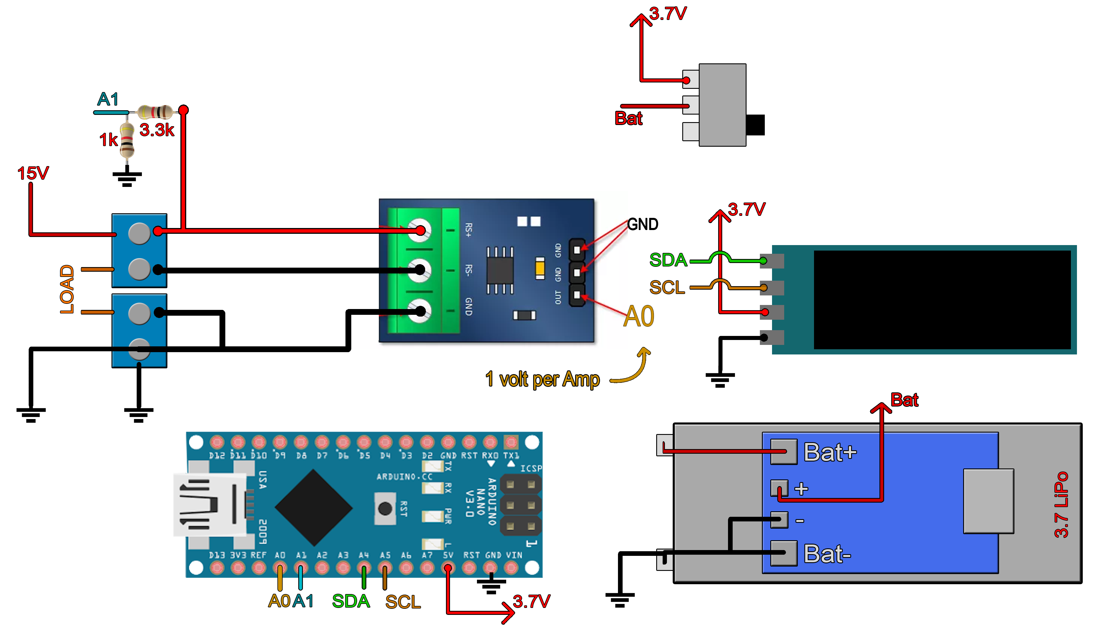
Below, you will also find the schematic and codes for the same project but using the current meter module. This module will sense the current without the huge shunt resistor and the extra OpAmp circuit so that will make the project smaller and probably easier. So, check the links below for all the extra schematics and codes. Use any USB charger to charge the battery. Be careful, the boar input has polarity. The load in the middle, and positive on one side and ground on the other, otherwise the board won’t work.
void get_values()
{
  voltage = (fmap(analogRead(A1),0.0,1023.0,0.0,3.7)) / 0.218;
  //The module gives one volt per Amp.
  RawValue = analogRead(A0);
  current = (RawValue * 5.0 )/ 1024.0; // scale the ADC, we get current value in Amps

  power = voltage*current;              //Calculate power and energy
  energy = energy + (power/3600)/1000;
}


